Note: Descriptions are shown in the official language in which they were submitted.
t 335 ~ 56
TURF ANCHOR AND PROCESS FOR USIN~ THE SAME
This invention relates to anchors for
securing loose turf such as divots or sod strips in
place and to the process for using such anchors.
In playing the game of golf, divots are
frequently dug from the grass of a golf course by a
golfer driving a golf ball. It is customary for
golfers or greenkeepers to replace divots in the
cavities or depressions in the lawn formed by their
removal and to step on the divots to press them back
into place. It has been found, however, that birds can
detect a divot that has been removed and replaced and
in seeking worms a bird can lift the edges of divots
with their beaks or claws to look for worms under the
divots more easily than worms can be found by
prospecting in the grass.
Divots partially or completely lifted by
birds can, of course, be reset, but such resetting
requires time and, if a divot is only partially lifted,
it is more difficult to see such a divot than if it
were completely removed.
As far as known to the inventor, no procedure
has been followed for anchoring or securing in place
replaced divots and the practice customarily followed
in replacing divots has been simply to press them into
their recesses manually or usually by foot pressure.
It is a principal ob~ect of the invention to
anchor divots replaced in the depressions from which
they were extracted, rather than relying merely on
pressure in resetting them.
~: 1
. ., ,~ .
1 3 3 5 1 5~
Another object is to provid~e a stake for
securing a divot in place which can penetrate turf
easily so that it can be driven by applying little
force to it but which will be difficult to withdraw.
A further object is to provide a turf anchor
stake which will effect minimum mutilation of the turf
and which when placed will provide minimal surface
exposure so as to be unobtrusive.
It is also an object to provide a divot
anchor that will deter turning of the divot about an
upright axis as well as deterring it from being lifted.
An additional object is to provide a turf
anchor that will deteriorate rather rapidly, such as by
being disintegrated by water, so that the anchor has
substantially disappeared in a short time after being
implanted in ground.
Aspects of the foregoing objects can be
accomplished by a process for replacing a divot dug by
a golf club from a golf course which comprises the
. .
steps of positioning said divot in the depression in
the golf course from which it was removed, impaling
said divot with a stake made of a material which will
disintegrate within a few weeks and of a suitable size
to anchor said divot in such depression, and leaving
said stake in place to prevent movement of said divot
out of such depression during a long enough time span
to permit root growth to occur for securing said divot
again in such depression prior to disintegration of the
stake.
Aspects of such objects also can be
accomplished by a divot anchor comprising a stake made
principally of peat material of a size suitable for
; ~ 2
1 335 1 56
club in the depression in the golf cour6e from which it
was dug with its tip embedded in the soil beneath the
divot, and the material of which the stake is made will
disintegrate within a few weeks when subjected to
water, during which period root growth of the divot has
again secured the divot in place in such depression
prior to disintegration of the stake.
Additional aspects of such objects can also
be accomplished by a divot anchor comprising a stake
made principally of peat material for impaling a loose
divot with its tip embedded in the soil beneath the
divot, and having a flat shaft to deter turning of the
loose divot about an upright axis, and the material of
which the stake is made will disintegrate within a few
weeks when subjected to water.
Additional aspects of such objects also can
be accomplished by a turf anchor comprising a stake
made principally of peat material for impalirg loose
turf with its tip embedded in the soil beneath the
turf, having a flat shaft to deter turning of the loose
turf about an upright axis and having a projection
extending laterally from the lower end portion of said
stake shaft for embedment in the soil to deter upward
withdrawal of the stake, and the material of which the
stake is made will disintegrate within a few weeks when
subjected to water.
In drawings which illustrate the preferred
embodiments of the invention,
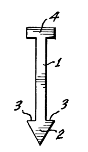
Figure 1 is a side elevation of a single
shank divot or turf anchor stake having a shank with a
triangular point, and Figure 2 is a top perspective of
such stake,
, , . ~
,.,,,,,, ...,
~:~ ,
` 1 3351 56
Figure 3 is a side elevation of a single
shank divot or turf anchor stake having a shank with an
arrowhead tip, and Figure 4 is a top perspective of
such stake,
Figure 5 is a side elevation of a staple
divot or turf anchor stake having twin shanks the
pointed lower ends of which have inwardly directed
barbs, and Figure 6 is a top perspective of such stake,
Figure 7 is a side elevation of a staple
divot or turf anchor stake having twin shanks the lower
ends of which are pointed and one of which has an
inwardly directed barb, and Figure 8 is a top
perspective of such stake,
Figure 9 is a side elevation of a staple
divot or turf anchor stake having twin shanks with
chisel-pointed tips, and Figure 10 is a top perspective
of such stake,
Figure 11 is a side elevation of a staple
divot or turf anchor stake having twin shanks with
double-tapered pointed tips, and Figure 12 is a top
perspective of such stake.
The divot or turf anchor stake of the present
invention may be of different shapes, representative
forms of which are shown in the drawings and are of a
size suitable to anchor a divot in the depression in
the golf course from which it was dug by a golf club.
In each instance the stake would have a shank long
enough to impale a loose divot or turf and to enable
its lower end portion to be embedded in the soil
beneath the divot or turf. Such a stake would have a
length of one to four inches. Particularly if the
lower end portion of the stake has a projection
:~
1 3351 56
extending laterally from it, such as a~barb, to deter
upward withdrawal of the stake, the shorter stake would
be of sufflcient length in most instances. Stakes of
different length could, however, be supplied.
Stakes of different configuration are shown
in the drawings. In Figures 1, 2, 3 and 4, divot or
sod anchor stakes having a single shank 1 are shown.
As shown in Figures 2 and 4, the stakes are flat, the
shaft having a width considerably greater than its
thickness. The stake shown in Figures 1 and 2 has a
pointed lower end, the upper portion of which has
pro~ections extending laterally oppositely from the
4a
- .
:k:
1 3351 56
opposite edges of the stake to form shoulders 3 that
would engage subsoil beneath a divot or loose sod for
creating resistance to upward withdrawal of the stake
and deter lifting of the divot or shifting of the sod.
Also the flat shape deters turning of the divot about
an upright axis.
The upper end of the shank 1 carries a
crossbar 4 which in the forms of turf anchor stakes
shown in Figures 1 to 4, inclusive, has cantilever ends
projecting laterally beyond opposite edges of the
shank. Such head can be impacted or pressed to drive
the stake shank through loose turf or a divot and
implant its tip in the subsoil beneath the turf or
divot.
Greater resistance to withdrawal of the stake
can be effected by making its pointed tip in the form
of a barbed arrowhead 5 having barbs 6 projecting
laterally from the opposite edges of the lower end
portion of the stake as shown in Figures 3 and 4.
The types of turf anchor stakes shown in
Figures 5 to 12, inclusive, have twin shanks 7 which
again are flat and are disposed in spaced coplanar
parallel relationship. The lower end portions of the
shanks of the stake shown in Figures 5 and 6 have
chisel points and the upper portions of the shank tips
have projections extending laterally inward from the
edges of the shanks to form shoulders or barbs 9 that
can be driven into the subsoil beneath the turf. Such
shoulders or barbs will produce resistance to deter
upward withdrawal of the stakes, as discussed in
connection with Figures 1 through 4.
1 3351 56
In each of the stakes shown'in Figures 5
through 12, inclusive, the upper ends of the twin
shanks 7 are connected by a crossbar 10 to provide a
stake of staple shape. Such stakes can be driven by
applying pressure to the crossbar 10 or by striking
such crossbar. The staple shape deters turning of the
divot about an upright axis. -
In the turf anchor stake shown in Figures 7
and 8, the tip of only one shank is formed as a chisel
point having a projection extending laterally inward
from the inner edge of its shank to form`a shoulder or
barb 9. The tip of the other shank is formed as a
chisel point 11, but such tip does not have a
projection extending laterally inward from the inner
edge of the shank to form a shoulder or barb that would
deter upward withdrawal of the stake.
In the forms of turf anchor stake shown in
Figures 9 through 12, neither of the shanks 7 has a
shoulder or barb on its tip to increase deterrence to
upward withdrawal of the stake. The tips of the twin
shanks of the stake shown in Figures 9 and 10 simply
have chisel points 11 like that described in connection
with the turf anchor staple shown in Figures 7 and 8.
Two adjacent sides of the tips of the rectangular cross
section twin shanks 7 of the turf anchor stake shown in
Figures 11 and 12 are beveled to form points tapered in
both directions to make them sharper than the tips of
the shanks shown in Figures 9 and 10.
The types of turf anchor stakes shown in
Figures 1 through 6 are for use where the soil under
the loose turf is soft so that the stakes can be driven
relative easily and will have good resistance to
, ~ . r r
1 3351 56
withdrawal even though the soil is soft. The turf
anchor stake shown in Figures 7 and 8 can be used where
the soil is more firm, and the turf anchor stake shown
in Figures 9 and 10 can be used where the soil is still
harder. The turf anchor stake shown in Figures 11 and
12 should be used where the soil is hardest in order to
enable the points 12 to penetrate a substantial
distance into the soil. The friction of hard soil with
the lower end portions of the turf anchor stake shank
would be sufficiently great to deter upward withdrawal
of the stake even without a lateral projection or barb
of the type discussed in connection with the stakes
shown in Figures 1 through 8, inclusive, if the stake
shank is long enough.
Penetration of the turf anchor stake is
facilitated by making it flat. Also, such flat shape
enables the crossbar head 4 or 10 to be substantially
embedded in the upper portion of the turf so that the
stake is not obtrusive or even easily detected.
Moreover, the head of the turf anchor stake is
sufficiently embedded in the upper portion of the turf
so as to not be struck by the blades of a lawnmower
cutting the grass even in making a close cut.
The need for securing loose turf such as a
divot or sod strip in place is relatively temporary,
that is, until the root structure can penetrate
appreciably into the soil beneath the turf. Such
attachment of the turf will usually take several weeks,
but the time required will be shorter if the grass is
watered normally. It is desired to avoid the trouble
and expense of extracting the turf anchor stakes when
the divots or sod strips have grown into place. To
....
1 33~ 1 56
avoid removing the turf anchor stakes, they are made of
material that will deteriorate rapidly, that is, the
integrity of the body of the stake will be destroyed
within a few weeks, particularly under moist conditions
which promote root growth. Such deterioration can
occur by making the stake of material that can either
be dissolved gradually by irrigation water or can be
disintegrated into powder or small fragments by such
water.
A preferred material from which the stakes
are made is peat or peat moss that can be molded to the
desired shape of stake described above either simply by
being compacted under pressure, or by being bound
together with a suitable binder, or both. Disintegra-
tion of the peat material can be expedited if the
binder is water soluble.
Other materials of which the stake can be
made include sugar-based material such as hard candy,
cornstalks, sawdust, cardboard, particle board, bagasse
and wood pulp with binders, if necessary, suitable for
accomplishing an initially firm material capable of
dissolving or disintegrating under moist conditions
within a few weeks.