Language selection

Search

Patent 1335413 Summary

Third-party information liability

Some of the information on this Web page has been provided by external sources. The Government of Canada is not responsible for the accuracy, reliability or currency of the information supplied by external sources. Users wishing to rely upon this information should consult directly with the source of the information. Content provided by external sources is not subject to official languages, privacy and accessibility requirements.

Claims and Abstract availability

Any discrepancies in the text and image of the Claims and Abstract are due to differing posting times. Text of the Claims and Abstract are posted:

  • At the time the application is open to public inspection;
  • At the time of issue of the patent (grant).
(12) Patent: (11) CA 1335413
(21) Application Number: 614678
(54) English Title: METHOD AND INSTALLATION FOR DISPLACING A JACKET OF AN ARTIFICIAL ISLAND IN RELATION TO AN UNDERWATER BASE
(54) French Title: METHODE ET INSTALLATION PERMETTANT DE DEPLACER LE TREILLIS D'UNE ILE ARTIFICIELLE SUR LE FOND MARIN
Status: Deemed expired
Bibliographic Data
(52) Canadian Patent Classification (CPC):
  • 61/6
(51) International Patent Classification (IPC):
  • E02D 25/00 (2006.01)
  • B63B 35/00 (2006.01)
(72) Inventors :
  • KALDENBACH, WILLEM PAUL (Netherlands (Kingdom of the))
(73) Owners :
  • ALLSEAS ENGINEERING B.V. (Netherlands (Kingdom of the))
(71) Applicants :
(74) Agent: FETHERSTONHAUGH & CO.
(74) Associate agent:
(45) Issued: 1995-05-02
(22) Filed Date: 1989-09-29
Availability of licence: N/A
(25) Language of filing: English

Patent Cooperation Treaty (PCT): No

(30) Application Priority Data:
Application No. Country/Territory Date
88.02431 Netherlands (Kingdom of the) 1988-10-04

Abstracts

English Abstract


Method and installation for displacing a jacket of an
artificial island in relation to an underwater base


When putting a jacket of an artificial island on an
underwater base, this jacket is swivelled downwards between
two vesselelements, being supported by a carrier which is pi-
votably suspended to the vessel elements.


Claims

Note: Claims are shown in the official language in which they were submitted.


THE EMBODIMENTS OF THE INVENTION IN WHICH AN EXCLUSIVE
PROPERTY OR PRIVILEGE IS CLAIMED ARE DEFINED AS FOLLOWS:

1. The method of placing an artificial island structure in
a vertical standing position on a underwater base site, which
comprises the steps of:
(a) loading the artificial island structure, while
horizontal, from land onto a buoyant carrier disposed in water,
(b) affixing the horizontal artificial island to the
carrier,
(c) transporting the carrier through the water to a large
displacement buoyant vessel,
(d) journalling one end of the carrier upon the vessel,
(e) transporting the vessel to a position over the
underwater base site,
(f) ballasting the carrier until the carrier swings
vertically downwardly about said one end of the carrier to an
upright position of the carrier and artificial island affixed
thereto,
(g) suspending the upright artificial island from the
vessel,
(h) disconnecting the carrier from the artificial island
structure, and
(i) lowering the artificial island structure relative to the
vessel until it is supported in vertical position on the under-
water base site.


6

2. The method as defined in claim 1 wherein step (b)
comprises temporarily welding the horizontal island structure to
the carrier and step (g) comprises ballasting the carrier
sufficiently to break the temporary weld.


3. The method as defined in claim 1, including between
steps (d) and (e), the step (d) of supporting a second end of the
carrier upon the vessel, and between steps (e) and (f) the step
(e) of discontinuing the support of the second end of the carrier
upon the vessel.


4. The method as defined in claim 1, wherein step (g)
comprises attaching said artificial island to beam means supported
by floater bodies floating in liquid-containing chambers in said
vessel, and wherein step (i) includes removing liquid from said
liquid-containing chambers to lower said beam means and thus said
artificial island.


5. The method as defined in claim 4, wherein simultaneously
with removing liquid from said liquid-containing chambers in step
(i) liquid is supplied into said floater bodies.


6. Apparatus for placing an artificial island structure in
a vertical standing position on an underwater base side, which
comprises:
buoyant carrier means for supporting the artificial island


7

structure and moving the artificial island structure over water to
a vessel means,
means for affixing the artificial island to the carrier
means,
vessel means for transporting the carrier means with affixed
island structure to a location over the underwater base site,
means for journalling one end of the carrier means upon the
vessel means,
means for ballasting the carrier means to swing it vertically
downwardly about said one end thereof to an upright position of
the carrier means and artificial island affixed thereto,
means for suspending the upright artificial island from the
vessel means, and
means for lowering the artificial island structure relative
to the vessel until it is supported in vertical position on the
underwater base site.


7. Apparatus as defined in claim 6, wherein said vessel
means includes mechanism for ballasting the vessel means with
water.


8. Apparatus as defined in claim 6, wherein said vessel
means includes two spaced apart vessel elements between which said
carrier means can be moved and supported.


9. Apparatus as defined in claim 8, wherein said carrier
means includes bearing shafts extending away from respective


8

opposite sides thereof at said one end thereof, and wherein facing
sides of said spaced apart vessel elements include respective
bearings in which said bearing shafts are respectively mountable.


10. Apparatus as defined in claim 9, including pneumatic
buffer means attached to each said bearing.


11. Apparatus as defined in claim 8, including support means
for temporarily supporting a second end of said carrier means upon
the vessel means.


12. Apparatus as defined in claim 8, wherein each of said
vessel elements defines a first liquid-containing chamber, wherein
a floater body means is positioned in the first liquid-containing
chamber in each of said vessel elements, and wherein said means
for suspending the upright artificial island from said vessel
means comprises a first beam member having opposite ends
respectively supported on said floater body means in said first
liquid-containing chambers.


13. Apparatus as defined in claim 12, including first chain
means connectable between said first beam member and said
artificial island.


14. Apparatus as defined in claim 12, wherein each of said
vessel means defines a second liquid-containing chamber, wherein a
floater body means is positioned in each of said second liquid-


9

containing chambers, and wherein said means for suspending the
upright artificial island from said vessel means comprises a
second beam member having opposite ends respectively supported by
said floater body means in said second liquid-containing chambers.


15. Apparatus as defined in claim 14, including second chain
means connectable between said second beam member and said
artificial island.


16. The apparatus as defined in claim 12, wherein said
floater body means define internal liquid-containing spaces, the
amount of liquid therein determining their buoyancy.


Description

Note: Descriptions are shown in the official language in which they were submitted.


1 1 3354 1 3 21766-558

The lnventlon relates to a method for dlsplaclng a
~acket or structure of an artlflclal lsland ln relatlon to an
underwater base.
In the known method of the above-mentloned klnd the
~acket or structure ls pushed from a floatlng pontoon lnto the
water. The ~acket or structure, whlch may for example be 100
metres long, ls thereby sub~ected to a large measure of local
loadlng durlng the slldlng contact wlth the edge of the pontoon.
The ~acket or structure has for thls reason to be strongly
Gonstructed to be able to wlthstand thls loadlng. Thls requlres
the use of much costly materlal.
The lnventlon has for lts ob~ect to provlde a method
whereby maneuverlng of the ~acket or structure ls carrled out such
that great locallzed loadlng does not occur and the ~acket or
structure can therefore be constructed sufflclently robustly wlth
less rnaterlal.
To thls end the lnventlon provldes the method of placlng
an artlflclal lsland structure ln a vertlcal ætandlng posltlon on
a underwater base slte, whlch comprlses the steps of:
~a) loadlng the artlflclal lsland structure, whlle
horlzontal, from land onto a buoyant carrler dlsposed ln water,
~b) afflxlng the horlzontal artlflclal lsland to the
carrler,
(c) transportlng the carrler through the water to a large
dlsplacement buoyant vessel,
(d) ~ournalllng one end of the carrler upon the vessel,
B

la 1 3 3 S 4 1 3 21766-558

(e) transportlng the vessel to a positlon over the
underwater base slte,
(f) ballastlng the carrler untll the carrler swlngs
vertlcally downwardly about sald one end of the carrler to an
uprlght posltlon of the carrler and artlflclal lsland afflxed
thereto,
(g) suspendlng the uprlght artlflclal lsland from the
vessel,
(h) dlsconnectlng the carrler from the artlflclal lsland
structure, and
(1) lowerlng the artiflclal lsland structure relatlve to the
vessel untll lt is supported ln vertlcal posltlon on the under-
water base slte.
The lnventlon further provldes apparatus for placlng an
artlflclal lsland structure ln a vertlcal standlng posltlon on an
underwater base slde, whlch comprlses:
buoyant carrler means for supportlng the artlflclal lsland
structure and movlng the artiflclal lsland structure over water to
a vessel means,
means for afflxlng the artlflclal lsland to the carrler
means,
vessel means for transportlng the carrler means wlth afflxed
lsland structure to a locatlon over the underwater base slte,
means for ~ournalllng one end of the carrler means upon the
vessel means,
means for ballastlng the carrler means to swlng lt vertlcally
downwardly about sald one end thereof to an uprlght posltlon of

lb 1 3354 1 3 21766-558

the carrler means and artlflclal lsland afflxed thereto,
means for suspendlng the uprlght artlflclal lsland from the
vessel means, and
means for lowerlng the artlflclal lsland structure relatlve
to the vessel untll lt ls supported ln vertlcal posltlon on the
underwater base slte.
The above features and others are elucldated ln the
followlng descrlptlon wlth reference to the drawlngs whereln:
In the drawlng ln schematlc form:
Flg. 1-5 show successlve steps for performlng a
preferred embodlment of the method accordlng to the lnventlon.
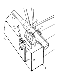
Flg. 6 shows on a larger scale a perspectlve vlew of
detall VI from Flg. 2.
Flg. 7 shows on a larger scale a perspectlve vlew of
detall VII from Flg. 3.


2 1 335 4 1 3


Fig. 8 shows on a larger scale a perspective view
of detail VIII from fig. 3, and
Fig. 9 shows on a larger scale a perspective, broken
away view of detail IX from fig. 5.
With the method according to the invention a jacket
3 manufactured onshore is rolled from the quayside as accor-
ding to arrows 14 by means of separate roller means 11 onto a
carrier 2 to which it is welded for a firm attachment during
transport. The carrier 2 which is thus loaded with jacket 3
and which has sufficient buoyancy for this purpose, is towed
in the water to the vessel 41 of the installation 1, anchored
for instance at sea outside a harbour, and arranged between
two vessel elements 4 of vessel 41 disposed at an interval
from one another. Two bearing shafts 19 of the carrier 2 are
accommodated in a ballasted vessel 41 in bearings 22 which
are suspended by means of hydropneumatic buffers 23 for exam-
ple from the vessel elements 4, and during transport the
carrier 2 is further suspended on the vessel elements 4 by
means of consoles 65 welded in position on vessel elements 4.
The vessel 41 is then freed of ballast and navigated to the
placing location. The consoles 65 are there cut free while
the carrier 2 is then supported by means of cables 29 which
run via guide pulleys 32 to winches, these guide pulleys 32
being carried by buffers 35. Hydraulically retractable con-
soles can also be considered for use instead of removableconsoles 65. After the vessel 41 is anchored above the placing
location in the required direction the jacket 3 is set in
position on the underwater base 36 as follows.
In order to carry the carrier 2 together with the
jacket 3 from the prone position into the downward directed
position, the free end of carrier 2 is ballasted with water
via valves 55 with the cables 29 under spring tension. For
this purpose the carrier 2 comprises watertight chambers 40
in the lower part of which are arranged pressure resistant,
cylindrical air tanks 39 which may optionally be placed under
a pressure via an air line 42 with a valve 45, this pressure

1 33541 3


being high enough to withstand the high external water pres-
sure of for example lO bar.
While the carrier 2 with the jacket 3 connected
thereto hangs on the bearings 22, the jacket 3 is suspended
by means of chains 57 to girders 9 which are supported by
floater bodies 8 accommodated in liquid baths 7 of the vessel
elements 4.
The vessel 41 preferably consists of two identical
supertankers which each form a vessel element 4. The loading
spaces thereof are converted into liquid baths 7 in which are
arranged floater bodies 8. The latter consist of tanks of
such a large volume that their buoyancy can together bear at
least the weight of the jacket 3, carrier 2, floater bodies 8
and supporting girders 9 when they are floating in water 10
present in the liquid baths. The floater bodies 8 are raised
by filling liquid baths 7 with water and by removing water
from the floater bodies 8.
The carrier 2 is then released from the upper part
of jacket 3 by adding a slight additional water ballasting to
the carrier 2, which results in the weld plates 26 being
released from the associated consoles 70 (figure 8). Carrier
2 is subsequently placed at a distance from jacket 2, using
for instance a lifting device 56 and a cable 69, into the
position drawn in figure 4 in dashed lines. Ballast water can
if required be thereby removed from the carrier 2. The jacket
3, which is positioned for example 4 metres above the base
36, is then set down thereon by bringing the floater bodies 8
down to a lower level.
Because the floater bodies 8 support the jacket 3
and because swell compensators 15 are arranged between the
girders 9 and the vessel elements 4, the swell of the vessel
41 during this operation is transmitted only to a very small
extent and with small forces onto jacket 3. The girders 9
support on the floater bodies 8 via columns 60 which are
provided with ball and socket joints 59. Girders 9 are held


1 3354 1 3

in position with control cylinders 67 provided with ball and
socket joints 68. Jacket 3 is first moved to a position a
short distance, for example 1 metre, above the base 36 and
then, preferably quickly, set down thereon. To this end the
water level 37 in the liquid baths 7 is lowered rapidly and/or
the floater bodies 8 are rapidly ballasted with water. Valves
30 are opened for this purpose to allow water to flow from
the baths 7 into floater bodies 8. When jacket 3 is standing
on the base 36 the chains 57 are released, the installation 1
is removed and the carrier 2 is suspended in the bearings 22
and raised to the prone position.
It is noted that a jacket 3 standing on the base 36
can be removed using the installation 1 by performing the
method substantially in the reverse manner. Means for this
purpose (not drawn) are present to pump either water out of
the floater bodies 8 and out of storage tanks 40 or surroun-
ding outside water into the baths 7.
- The installation 1 can be used for the placing and
removal of jackets 3 at varying water depths. To this end a
piece 64 of the carrier 2 of suitable length d is then in-
serted therein by means of welding operations or removed
therefrom to adapt the total length of carrier 2 to the depth
of water or length of the jacket 2 occurring in each case.
Using one and the same installation 1 a jacket 3 can in this
way be placed or removed at a depth of water of 80, 100. 120
or 150 metres.

*****

Representative Drawing
A single figure which represents the drawing illustrating the invention.
Administrative Status

For a clearer understanding of the status of the application/patent presented on this page, the site Disclaimer , as well as the definitions for Patent , Administrative Status , Maintenance Fee  and Payment History  should be consulted.

Administrative Status

Title Date
Forecasted Issue Date 1995-05-02
(22) Filed 1989-09-29
(45) Issued 1995-05-02
Deemed Expired 1999-05-03

Abandonment History

There is no abandonment history.

Payment History

Fee Type Anniversary Year Due Date Amount Paid Paid Date
Application Fee $0.00 1989-09-29
Registration of a document - section 124 $0.00 1990-01-11
Maintenance Fee - Patent - Old Act 2 1997-05-02 $300.00 1997-05-27
Owners on Record

Note: Records showing the ownership history in alphabetical order.

Current Owners on Record
ALLSEAS ENGINEERING B.V.
Past Owners on Record
KALDENBACH, WILLEM PAUL
Past Owners that do not appear in the "Owners on Record" listing will appear in other documentation within the application.
Documents

To view selected files, please enter reCAPTCHA code :


To view images, click a link in the Document Description column. To download the documents, select one or more checkboxes in the first column and then click the "Download Selected in PDF format (Zip Archive)" or the "Download Selected as Single PDF" button.

List of published and non-published patent-specific documents on the CPD .

If you have any difficulty accessing content, you can call the Client Service Centre at 1-866-997-1936 or send them an e-mail at CIPO Client Service Centre.


Document
Description 
Date
(yyyy-mm-dd) 
Number of pages   Size of Image (KB) 
Representative Drawing 2002-03-06 1 10
Claims 1995-05-02 5 147
Drawings 1995-05-02 8 278
Cover Page 1995-05-02 1 18
Abstract 1995-05-02 1 11
Description 1995-05-02 6 205
Examiner Requisition 1992-03-18 1 74
Prosecution Correspondence 1992-06-23 2 38
Examiner Requisition 1994-06-23 2 97
Prosecution Correspondence 1994-10-24 1 41
PCT Correspondence 1995-02-03 1 31