Note: Descriptions are shown in the official language in which they were submitted.
`-- 1 33570 1
The present invention relates to storage and
filing devices, and particularly to improvements in
files and portable storage devices for such files.
A perennial problem for travellers is to keep
their belongings organized throughout the journey.
This is particularly difficult for business travellers,
who may, in the course of a single journey, have to
visit several business associates, and/or visit differ-
ent places and even different countries, and/or deal
with numerous different matters, at the same time being
severely restricted as to the amount of luggage they
can carry, particularly when travelling by air and
staying in hotels. Using conventional luggage, brief-
cases, and the like, it can be extremely difficult to
keep business papers and other belongings organized
throughout a journey, and in particular, to keep things
separate from one another so that particular papers or
other belongings can be located ~uickly, and so that
individual matters can be dealt with expeditiously
during the journey and on return to base.
A conventional briefcase, even if provided
with multiple pockets, is inconvenient because the
contents of individual pockets are not immediately
apparent, and it may well be necessary to unpack the
entire contents to locate particular things. Carrying
individual separate folders in a suitcase or a brief-
case can help, but is not a complete solution, as the
individual folders still have to be unpacked from
luggage and repacked, possibly many times in the course
of a journey, leading to inconvenience and untidiness,
and unless the user is exceptionally meticulous, such
folders will normally be packed and repacked in varying
order in the course of a journey, so that what they
contain is not always presented to the traveller in the
same order.
1 335701
Loose-leaf products, for example, "Filofax"
(Registered Trade Mark) and similar "organizers", are
excellent for storing and presenting information such
as dates and notes, but are of little use for organiz-
ing things like bills, letters, reports, tickets,
currency, and the numerous other pieces of paper and
other articles that travellers commonly put in brief-
cases or pockets.
Consequently, there is a need for a device
which will enable the traveller to organize his papers
at the beginning of and during a journey, and to
maintain that organization and, in particular, the
distribution and order of presentation of individual
matters throughout the journey, which is capable of
being easily carried and occupies little space when in
use, for example, in a hotel room.
It is known to provide a storage device with
a series of envelopes attached one to the other by
connecting means. An example of such a construction is
20shown in U.S. Patent 4,706,396, issued November 17,
1987.
The bags described in U.S. Patent 4,706,396
are permanently attached to each other. Further, the
attachments are short strips extending from the front
face of one bag to the rear face of the adjacent offset
bag. SUch a construction requires that the front and
rear faces of the bags be reasonably rigid and that the
bag construction be strong in order to transfer the
weight of succeeding bags and their contents without
otherwise deforming the bags.
It is an aim of the present invention to
provide an improved portable file storage and carrying
system, including an improved pouch suspension struc-
ture wherein the pouches are not subjected to the
weight of succeeding pouches.
_ 3 _ 1335701
It is a further aim of the present invention
to provide an improved pouch which can serve as a file
for papers as well as for other heavier items such as
coins and tools, and which can be used in a portable
storage device or be removed from the storage system
and handled individually or placed in a conventional
file cabinet.
A further aim of the present invention is to
provide an improved file labeling system.
According to the invention, the pouch suspen-
sion means comprise at least an elongated foldable
member or the like separate from the pouches, and the
pouches are attached to the elongated foldable member
in such a manner that they overlap one with the other.
In a more specific embodiment, the pouches
are releasably attached to the foldable member in order
to be able to take an individual pouch and its contents
to a particular meeting.
A further construction in accordance with the
present invention includes a storage and filing device
comprising a pouch suspension in the form of at least
an elongated foldable member, including rigid compo-
nents integral with and spaced apart longitudinally of
the elongated member and flexible portions of the
foldable member extending between the rigid components.
A plurality of pouches have top and bottom edges and
attachment means near the top edge of each pouch for
attaching the pouches to respective components, such
that the pouches overlap on the elongated foldable
members in an open condition, and the pouches can be
stacked one against each other while attached to the
components of the foldable members in a closed posi-
tion.
In a more specific embodiment of the present
invention, there is provided a storage cover member, a
pair of parallel foldable strap members, each connected
at one end to the cover member. Pairs of rigid compo-
1 335701
nents are provided, one of each pair on each strap.Corresponding ones of the components are spaced apart
on each strap by a flexible portion of the strap
providing foldable hinge portions. A plurality of
pouches are provided with each pouch including a top
edge, a bottom edge and sides, and an opening near the
top edge. A relatively stiff suspension bar extends
the width of the pouch along or near the top edge and
includes, at each end thereof, fastening means for
detachably engaging respective components of a selected
pair of components. In an open hanging position, the
pouches arranged on the straps overlap each other with
the top edges thereof exposed. In a closed position,
the pouches are stacked, one against each other, with
the straps in a concertina arrangement, and within the
confines of the cover.
Accordingly, the present invention also
resides in labelling means comprising a support provi-
ded with a recess having a pair of opposite ends which
are undercut, and a labelling member of semi-rigid
material having dimensions corresponding to the recess
and including opposite end regions matching the said
undercuts, whereby the labelling member can be disposed
in said recess and retained therein by said end regions
engaging in the undercuts, and the labelling member can
be removed from and inserted in the recess by bowing or
buckling of the labelling member to render its length
effectively less than that of the recess.
According to yet another aspect of the
present invention, there is provided a storage or
filing pouch having an opening in an upper region for
access to its interior, and at each side of the pouch
in the upper region thereof a single suspension hook,
snap or other connecting means.
_ 5 _ t 335701
According to still another aspect of the
invention, there is provided a storage or filing pouch
having an opening in an upper region for access to the
interior of the pouch, and a stiffener extending along
an upper edge of the pouch.
Having thus generally described the nature of
the invention, reference will now be made to the
accompanying drawings, showing by way of illustration,
a preferred embodiment thereof, and in which:
Fig. 1 is a perspective view of a storage and
filing device in accordance with the present invention,
shown in an open position;
Fig. 2 is a perspective view of the storage
and filing device of Fig. 1, shown in a closed posi-
tion;
Fig. 3 is a perspective view of a detail of
the present invention, and in particular, an embodiment
of a pouch;
Fig. 4 is an enlarged fragmentary view of a
detail in a different position of the embodiment shown
in Fig. l;
Fig. 5 is a side elevation of the embodiment
shown in Fig. 1, with certain elements thereof in
different operative positionsi
Fig. 6, which is on the same sheet as Fig. 1,
is an enlarged fragmentary exploded view of a detail of
the present invention;
Fig. 7 is an enlarged fragmentary elevation
of a detail of the element shown in Fig. 3;
Fig. 8 is a perspective view of a detail
shown in Fig. 7;
Fig. 9 is an enlarged fragmentary longi-
tudinal cross-section of a detail shown in Fig. 7 but
in a different operative position; and
Fig. 10 is a fragmentary enlarged longi-
tudinal cross-sectional view, similar to Fig. 9,
showing an element in a still further different opera-
iive position.
~' g~r
1 33570 1
-- 6
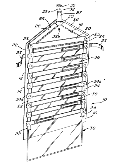
Figs. 1 to 5 illustrate a portable storage
and filing device 10, which includes an external bag or
case 11. This comprises a main or back panel 12, a
bottom panel 14, a front panel 16, and a top flap 18.
These parts are so arranged and interconnected that
they can be laid or hung in a flat condition as illus-
trated in Fig. 1, or folded to form a case as shown in
Fig. 2 with the bottom panel 14 forward of the back
panel 12, and the top flap 18 overlying the front panel
16 and fastened to it. At the hinge or junction
between the top flap 18 and back panel 12, there is a
rigid spine 20. A handle (not shown) may be fastened
so that the bag can be carried.
The panels and flaps of the case may be
rigid, semi-rigid, or soft, for example, of canvas,
provided with stiffeners at the edges and at the fold
lines, as appropriate.
A pair of reinforcing strips 26, 28, for
example, of molded plastic or a fabric, are fixed to
the inside surface of the top flap 18 and extend from
positions near the ends of the spine 20, converging to
an apex of the flap 18. The triangular structure made
up of spine 20 and strips 26 and 28 will, as described
further, provide the hanging structure for the filing
system. At the apex of the top flap 18, that is, at
the junction of the strips 26, 28, is a plate 30 to
which a hook 32 is connected by which the bag, when
unfolded, can be hung from a hook, a rail, the edge of
a door, or any other convenient suspension point. This
hook 32 can be folded and stowed under the top flap 18,
when the bag is closed.
In the illustrated embodiment, the back panel
has a pair of strips 33 of fastening material such as
"Velcro" (Registered Trade Mark), to mate with a
corresponding fastening strip or strips provided on the
front panel 16 for holding the bag closed. Any other
1 335 70 ~
-- 7
suitable fastening means can be provided, for example,
snap fasteners, a slide fastener, straps and buckles,
and so on.
Near each end of the spine 20, a respective
hanger strap 22, 24 is provided, made, for example, of
webbing. Releasable fasteners 23 and 25 are provided
to connect straps 22, 24 respectively to the spine 20,
so that the latter can be detached from the bag. These
fasteners 23, 25, as shown in the drawings, may be
conventional metal snap fasteners, or the straps 22, 24
could be stitched directly to the spine 20 or the back
panel 12.
The hanging straps could be readily detach-
able from the spine 20, so that the user can insert
longer or shorter straps.
The snap fasteners 23, 25 can be conventional
round snap fasteners. However, a minor disadvantage of
these is that the straps may tend to swivel outwards
when pouches are gathered into a stack. To avoid this,
the snap fasteners may have a non-circular, e.g.,
square or triangular, profile.
Pairs of suspension components 34 are provi-
ded at spaced-apart locations on the straps 22 and 24.
Each pair of components 34 includes a component 34a
mounted on the strap 22 and a component 34b mounted on
strap 24 at a corresponding level. The components, as
shown in Fig. 6, include a first panel 34z with flanges
34x and 34y. Centrally of the panel 34z, that is, on
the rear side thereof, there is provided a pin 41. A
back plate 56 is provided with a female opening 60 to
engage and lock onto the pin 41. Each component 34b,
in the case of Fig. 6, is fastened to the strap 24 by
punching pin 41 through the strap and fastening the
plate 56 between the flanges 34y and 34x and engaged by
the pin 41. Any number of pins 41 may be provided.
1 33570 1
-- 8
Each component 34a and 34b has a slight,
outwardly extending projection referred to by the
numeral 35 and a slight finger depression 37. These
features allow for better gripping of the components
during operation of the device.
As will be described later, the components 34
provide the straps 22 and 24 with intermittent rigid
portions separated by the flexible strap portions,
allowing the straps, when provided with pouches 36, to
~old neatly in a concertina fashion.
Pouch 36, as shown in Fig. 3, for instance,
includes a suspension bar 40 having at each end thereof
attachment devices 38a and 38b which will be described
later. The suspension bar 40 terminates at each end in
hook-shaped projections 42a and 42b. The pouch 36, as
shown in the embodiment of Fig. 3, is made of an
injection molded semi-rigid plastics. The suspension
bar 40 is molded in one piece with a peripheral frame
made up of side members 48a and 48b and bottom member
50. Panels 52 and 54 form the front and rear of the
pouch and are welded to the peripheral frame made up of
side members 48a, 48b, and bottom member 50 as well as
the suspension bar 40.
In the present embodiment, the panels 52 and
54 are shown as being transparent. of course, these
may be opaque. The pouch could have other forms and be
made of textile material with a plastic or metal
suspension bar. Likewise, the pouch 36 could also be
of paperboard with gusseted sides and bottoms attached
to a suspension bar of relatively stiff material.
However, the pouch shown in the present embodiment,
which includes a peripheral semi-rigid frame, gives
extra protection and strength to the pouch material and
the contents thereof and prevents material in the pouch
from folding in the case of paper material.
1 33570 1
g
A slit opening 46 is provided in the suspen-
sion bar 40 to provide access to the interior of the
pouch between the panels 52 and 54. The slit opening
may be open or closed by a slide fastener 37. Thus, in
a construction, the rear panel 54 is secured to an
upper part of the suspension bar 40 above the opening
46, and the front panel 52 of the pouch is welded to a
portion of the suspension bar below the opening 36 in
the slide fastener 37. The front, lower portion of the
suspension bar 40 provides stiffening for the slide
fastener 37 when closed so that the weight of the
contents in the pouch cannot pull open the pouch
opening closed by the fastener. It also stiffens the
pouch when it is open, it being able to bow forward to
facilitate access to the interior of the pouch.
Referring now to Figs. 4 and 6, the pouch 36
is illustrated as being detachably connected to the
components 34a and 34b. In the present embodiment, the
snap attachment is in the form of plastic snap fas-
teners 38a, 38b defined at each end of the suspension
bar 40. The back plate 56 of the component 34
includes a plastic male snap member 58 which is adapted
to snap into the female snap component 38b, as shown in
Fig. 6. The pouches 36 are meant to snap on the rear
of the straps 22 and 24, as shown in Figs. 4 and 5.
Once the pouch 36, with its relatively stiff
construction, that is, including the suspension bar 40
and, in this embodiment, the molded peripheral frame
48, 48b, and 50, is connected to the components 34a and
34b on respective straps 22 and 24, it is an easy
matter to close the storage device by grasping a pair
of components 34a and 34b corresponding to a lower
pouch 36, iOe., the bottom pouch as shown in Fig. 5,
and lifting the bottom pouch towards the top pouch 36.
This action causes the straps 22 and 24 to fold, but
for the components 34a and 34b to retain along with the
pouches 36 a parallel relationship such that the
- 10 - 1335701
flexible portions of the straps 22 and 24 will fold, as
shown in Fig. 5, but the components 34a and 34b and the
pouches 36 will stack in a parallel relationship until
all of the pouches have been grouped. The bottom wall
14 and the front wall 16 of the case 11 can then be
~olded into a position as shown in Fig. 2, and the
straps 33 closed over the front panel 16. When it is
required to open the storage and filing device, the
case 11 is hung by means of hook 32 onto a top door
edge or rail, and the panels 16 and 14 are allowed to
hang from the back panel 12. The pouches 36 will then
hang in a staggered manner from the straps 22 and 24 as
shown in Figs. 1 and 4. It is also possible, as shown
in Fig. 4, to detach one end of the suspension bar 40
of a pouch 36 from a component 34 which will cause the
pouch to swivel from the other attachment at component
34b, for instance, to allow more ready access into the
pouch 36.
The feature of the hooks 42a and 42b at the
ends of the suspension bar allows the pouch to be
placed in a typical filing cabinet, such as a filing
cabinet having pairs of tracks for receiving files with
hooks provided at the top end corners thereof. Typi-
cally, such conventional files have four hanging points
when, in fact, the present pouch construction allows a
file to be hung from only two hooks 42a and 42b. It is
also understood that the snap fasteners connecting the
pouches to the components can be of any conventional
construction, such as conventional snap fasteners.
Even "Velcro" fasteners could be contemplated in the
event of the storage of relatively light material'in
the pouches.
Although the pouches are contemplated to
contain paper sheet material such as usually found in
files, it could be utilized for storing photographs and
other travelling papers or as a travelling case with
various shirts and other clothing in different pouches.
1 335701
-- 11 --
Likewise, the pouches can be of sturdy material for
storing tools or the like. In such a case, the con-
struction of the straps, components, etc. would be
reinforced.
The pouch suspensiQn bar 40 is flexible
enough for it to bow, allowing the pouch to open along
with the slitted opening 46 for the pouch, into which
an opening and closing mechanism such as a slide
fastener 37 can be inserted. Alternatively, slide
fastener tracks can be formed integrally with the lips
of the slitted opening in the suspension bar. The
region of the suspension bar below the slot or opening
reinforces the front of the pouch when it is opened.
The suspension bar could be made of two flat strips
and, in fact, the molded peripheral frame can be made
in two flat pieces sandwiching the edges of the front
and rear panels.
It is envisaged that the suspension bars
and/or pouches incorporating suspension bars, will be
sold as separate products, which can be used in con-
junction with suspension straps, for example, as shown
in the drawings, or as closable removable pouches or
file folders in otherwise conventional filing systems
or in suspension filing systems specifically designed
for use with these pouches.
If snap fasteners are provided on the front
and rear of the suspension bars as represented by
fasteners 38a, 38b, these front and rear snap compo-
nents are complementary and can be used to fasten
pouches to one another to form a pack of pouches which
can be handled as a unit. The pouches may be provided
with permanent carrying handles, or detachable handles,
e.g., a separate handle with snap fasteners on front
and back matching those on the pouch suspension bar.
The ends of the suspension bar project
laterally beyond the sides of the pouch and form
suspension hooks 42a, 42b such that the suspension bar
1 33570 t
- 12 -
and pouch can be suspended on conventional suspension
filing supports, for example, in a lateral or vertical
suspension filing cabinet.
However, it is to be noted that, in contrast
to conventional suspension filing wallets which hang
from four support points, the present pouch is suspen-
ded from two support points at each end. As a result,
it can be suspended from suspension filing support
rails which are not necessarily horizontal whereas
conventional filing folders cannot.
The described devices have pairs of hanging
straps, one at each side. Cords or other flexible or
hinged suspension means can be provided. More or fewer
suspension means can be provided, for example, a single
strap or cord, to which the pouches are attached
centrally, or at upper corners of the pouches, with the
pouches hanging diagonally.
The straps or other suspension means may be
designed to allow the user to adjust the spacing
between pouches. For example, a suspension strap may
have a multiplicity of suspension points, each of which
may be provided with its own snap fastener, at a
relatively small pitch, so that the user can attach
pouches to it at any selected spacing.
To enable the user quickly to identify the
contents of a pouch, a large strip or patch of white or
other colour may be printed at the top of each pouch,
on which the user can write with a suitable marker, for
example, a water-soluble marker. A standard label
holder or holders may also be provided, permanently or
separably, on the pouches, in particular at the pouch
top.
A preferred labelling arrangement is illus-
trated in Figs. 7 to 10.
The upper region of the suspension bar 40 is
provided with an elongate rectangular recess 62 which
may be set into the body of the suspension bar 40 or
1 335701
- 13 -
may be defined by a frame protruding from the front of
the suspension bar 40. This recess 62 accommodates a
label holder 64 made of semi-rigid plastics or other
semi-rigid material. The label holder 64 is a substan-
tially rectangular strip, provided with a projecting
tongue 66, 68 of reduced thickness at each end, and a
slot 67 between the front and rear walls 69, 71 of the
label holder 64. A label 70 of paper, card or other
suitable material can be inserted into the slot 67 and
is visible through a window 75 in the front wall 69.
This window 75 may be a simple aperture or it may be
covered by a transparent sheet or layer.
At one end of the label holder 64, its front
surface is provided with a thumb grip 72, for example,
comprising transverse grooves.
The label holder 64 can be made in any
convenient way, for example, as an integral element of
extruded or injection moulded plastics material, or by
joining together front and rear strips of material to
define the slot 67.
The main portion of the label holder between
the tongues 66, 68 corresponds in shape and size to the
recess 62. At the ends, the recess 61 has undercuts
76, 78 corresponding to the tongues 66, 68. The label
holder 64 can, therefore, substantially fill the recess
62 and be held firmly in place by the tongues 66, 68
engaged in the undercuts 76, 78. The stiffness of the
label holder 64 ensures that it cannot be accidentally
dislodged from the recess.
To insert the label holder 64 in the recess,
one end of the label holder 64 is placed in the corres-
ponding end of the recess 62 so that its tongue 66
enters the corresponding undercut 76, and the label
holder 64 is bowed slightly so that the tongue 68 at
its other end can be inserted into the corresponding
undercut 78. Once inserted and allowed to return to
its natural flat shape, the label holder 64 is stiff
1 33s7al
- 14 -
enough to remain in place in the recess 62, held by its
tongues 66, 68. Shallow nipples may be provided in the
top and bottom side walls of the recess 62, midway
along its length, to retain the label holder even more
securely.
To remove the label holder, the user pushes
the region provided with the thumb grip 72 downward
towards the depression 74 in the bottom of the recess,
as shown in ~ig. 9. This causes the label holder 64 to
bow outwards, until the tongue 68 at the thumb grip end
72 of the label holder 64 moves clear of its undercut
78. The label holder 64 can then be lifted or sprung
out of the recess 62.
The outer end of the depression 74 may have a
sharp step against which the tongue 68 can lodge, once
it has moved past this step. This reduces the risk
that the label holder may accidentally snap back into
the corresponding undercut 78, and makes it easier to
manipulate the label holder 64.
The label holder 64 can be coded, for exam-
ple, by colour or by carrying one or more permanent
symbols.
If the label window 75 has a transparent
cover, or if the upper layer of the label holder is of
transparent material, the transparent material is
preferably such that it can be written on, for example,
with a felt or dye marker, so that the label holder 64
itself can be used as a label.
The label holder 64 may constitute the sole
labelling means, the slot 67 and insertable label 70
being omitted.
In one convenient construction, the label
holder 64 comprises a rear layer of semi-rigid plastics
material and a front layer of transparent semi-rigid
plastics material, the front layer being provided with
a border which conceals the edges of the label and
defines the window 75.
1 33~7al
- 15 -
The label 70, if used, can be made of stan-
dard paper of any weight or any other suitable mate-
rial. The labels themselves can, for example, be
provided as tear-off portions of a perforated sheet, in
well-known manner.
The described labelling system is extremely
simple, reliable and versatile. The label holder can
be removed or inserted in the recess using one hand,
and the label 70, if used, is automatically inserted or
removed with the label holder. Because the label 70 is
supported and protected on both sides, it can be made
of standard paper of any weight, which is, therefore,
easier to type, print or write on than conventional
filing system labels which are made of stiff paper or
card.
Since the labelling means is an integral part
of the pouch, neither the edges of the label nor the
end extensions 42a, 42b at the ends of the suspension
bar 40 can damage the bag or other enclosure since they
do not have sharp edges contrary to conventional
suspension file hooks which are likely to tear any bag
type enclosure in which they are placed.
Pouches specially designed to carry films,
tapes, computer discs and the like may be provided, and
may incorporate protection against damage by security
X-rays and the like.
The present invention has numerous applica-
tions. For example, with suitable selection of pouch
material and size, the device can be used for storing
and carrying tools and other equipment. The device can
be made of handbag size, or even pocket size, for
example, to carry several different currencies and
travel documents, passports, airline tickets and the
like. In a larger size, the device can be used to
carry and present designer's drawings, fabric samples,
photographs and the like; in this embodiment, the
1 335701
- 16 -
pouches may have built-in or removable mounts or frames
so that the drawing, fabric or photograph put in the
pouch is automatically presented with a frame.
The device can be used for display purposes
in shops, exhibitions and the like, for example, to
store and display manuscripts, music, compact discs,
stamps, coins, ties, prints, drawings, and so on.
For security, electric or electronic cir-
cuitry can be incorporated to provide a signal if a
pouch is removed, to provide a theft alarm, or an alert
signal to a cashier or other responsible person, and/or
to provide inventory control. For example, a conduc-
tive path extending along a belt 22, 24 may be broken
if a pouch is detached or if the belt is detached, cut,
or broken.
Although the pouches preferably have means
for fastening them closed, this is not essential. The
pouches may be so designed that, at least when detached
from the hanging straps, a pouch can be opened out flat
like a folder.
Figs. 1 to 6 illustrate a preferred design of
the device with improved pouches and suspension straps.
The tops of the straps 22, 24 are attached to a tri-
angular shaped hanger 85 formed by cross bar 20, strips
26 and 28, which is itself attached by a short strap 87
to an attachment means or a hook 32. The flexible
strap 87 enables the pouches and their connecting means
to swivel or rotate about a vertical axis defined by
the longitudinal direction of the strap 87. If the
strap 87 were rigid, there would be a tendency for the
hook 32 to become detached (i.e., dragged off) from its
support (not shown) during use of the device. The
support may be a rail, the edge of a door or other
convenient suspension point.
The triangular shaped hanger 85 comprises a
pair of flexible strips on arms 26, 28 which are linked
to the strap 87 via a coupling plate 30 so that the
- 17 - I 33570 1
strap 87 and arms 26, 28 together form a "Y" configura-
tion. Respective ends of the arms 26, 28 are fixed to
respective ends of the main suspension cross bar 20.
The main suspension cross bar 20 is sufficiently stiff
so that the bar 20 does not deflect outwardly when the
pouches are laden. The stiffness can be achieved by
reinforcing the bar 20 with steel. The main suspension
bar 20 could form the spine of the carrying means. In
this case, a carrying handle (not shown) could be
attached to the bar 20. The straps 22, 24 of the
connecting means are suspended from the ends of the
main suspension cross bar 20.
Snap fasteners (not shown) are provided on
the reverse side of the main suspension cross bar 20
from that shown in Fig. 1. Complementary snap fastener
components (not shown) are provided on the interior of
the bag or case for enabling bodily
detachment/attachment of the pouches, straps 22, 24,
and hanger 85 from/to the bag or case. The hook 32 may
have a snap fastener component 32a on its front so that
it can be attached to a corresponding snap fastener
component 32b provided in the bag or case, to keep the
hook safe and tidy.
Finger impressions or other markings may be
moulded into the triangular hanger 85 and the compo-
nents 34, on their front surfaces, to indicate the
positions of the snap fasteners on the rear.
The snap fasteners on the rear of the main
suspension cross bar 20 can also be used to attach the
hanger 85 to a board or panel provided with complemen-
tary snaps.
Snap fasteners 25, which are preferably
non-circular in profile to prevent the straps 22, 24
from swivelling outwards when the pouches are gathered
in a stack may optionally be provided for attaching the
straps 22, 24 to the hanger 85. The straps 22, 24 in
this embodiment are flexibly attached to the hanger 85.
- 18 - 1 33 ~ 701
The hook 32 incorporates a slot 35 which
facilitates moulding of the hook, and in addition can
be used for hanging on nails and the like.
The arms 26, 28 of the hanger 85 may have, in
cross-section, thicker edge regions and a thinner
intermediate region, to enable them to flex. Alterna-
tively, they may be formed from a woven material.