Note: Descriptions are shown in the official language in which they were submitted.
- 1 - 1 3 3 5 7 5 0
This is a divisional application of copending
application 588,001, filed January 11, 1992.
This invention relates to a composite material
comprising multifilament fibres, often referred to as
bundles, and a matrix material, the material having improved
planar tightness by which we mean an improved resistance to
fluid transfer generally parallel to a surface thereof.
Preferably fluid uptake and storage within the composite are
reduced.
Composite materials find wide use due, for example, to
the flexibility or alternatively tenacity (strength) they can
possess. We have found, however, that for many uses
multifilament fibres, which may be chosen as a component of a
composite material for their high flexibility etc., present
problems due to their ability to transmit air, water and
other contaminants.
We have further found that multifilament fibres (which
may provide strength and which may therefore be regarded as
comprising strength fibres) can be treated or constructed to
overcome such problems, thereby allowing their use where
fabrics or composites has not previously been used, or where
such articles had been made from mono-filament fibres. Such
treatment or construction results in a multifilament fibre
~ '~
1 335750
- la -
being blocked at one or more positions along its length, or
preferably substantially continuously along its length. A
block comprises some means that prevents or hinders passage
of fluid longitudinally along the interstices of a
multifilament fibre, and will generally comprise some
polymeric filling. Spaced apart blocks may prevent or reduce
fluid transfer along a fibre, but the fibre may still be
capable of taking up and storing fluid. That too may be
prevented or reduced by a substantially continuous block
along the fibre
~ -2- 1 335750 RK380
length.
The invention provides a composite material comprising:
(a) blocked multifilament fibres; and
(b) a polymeric matrix material, preferably that renders
the material substantially impervious to the passage of
liquid through t.e thickness of the article
The invention further provides a dimensionally-
recoverable article comprising:
(a) multifilament fibres, at least some of which at
least in the article after recovery (and preferably also
before recovery) are blocked by a polymeric material and
(b) a polymeric matrix material preferably that renders
the article substantially imper,vious to the passage of
liquid through the thickness of the article.
The multi-filament fibres preferably constitute
at least part of a fabric especially a woven fabric, par-
ticularly a dimensionally-recoverable fabric.
The invention also provides a composite material which
comprises:
(i) a polymeric matrix material,
(ii) multi-filament fibres
(iii) hybrid fibres (preferably comprising said multifi-
lament fibres) comprising
(a) a strength fibre (preferably a plurality of
strength fibres) and
(b)blocking material in the form of or formed from
heat-softenable fibres that on heating (and preferably also
compression and/or recovery) of the composite material will
3 1 335750 RK380
block interstices of the multifilament fibres (preferably
comprising interstices between the strength fibres).
The invention also provides a recoverable article
comprising;
(i) recoverable fibres exhibiting a recovery of at
least 20%;
(ii) multifilament fibres; and
(iii) hybrid fibres (preferably comprising said
multifilament fibres comprising
(a) a strength fibre (preferably a plurality of
strength fibres); and
(b) blocking material in the form of or formed from
heat-softenable fibres that on heating (and preferably also
compression and/or recovery) of the comrosite material will
block interstices of the multifilament fibres (preferably
comprising interstices between the strength fibres).
The invention further provides a method of making a
composite material which comprises:
(i) providing, preferably in the form of a fabric,
multifilament fibres and hybrid fibres (preferably
comprising said multifilament fibres), the hybrid fibres
comprising
(a) a strength fibre (preferably a plurality of
strength fibres) and
(b) blocking material in the form of heat-
softenable fibres that on heating (and preferably also
compression) of the multifilament fibres will block
interstices of the multifilament fibres (preferably
comprising interstices between the strength fibres);
1 335750 RK380
(ii) coating the fabric with a polymeric matrix
material;
(iii) heating (and preferably also compressing) the
hybrid fibres before, during or after coating to cause the
heat-softenable fibres to soften and block interstices of
the multifilament fibres.
Changes that can occur in a recoverable article on reco-
very (especially compression against an underlying substra-
te) or the heating step that may be used to cause recovery
or other heating or pressurising step applied to a reco-
verable article or composite material may cause a suitably
constructed, but non-planar tight, article to become planar
tight.
It may be desirable that an article or material be
supplied for its final use in a blocked or planar tight con-
dition, but that is not always necessary. Some further
treatment (which may comprise treatment inherent in use or
installation, such as heat-recovery as mentioned above) may
result in blocking or planar tightness. Various techniques
are disclosed herein, and the skilled reader will readily be
able to determine whether such further treatment is
necessary. For convenience, however, an article or material
may be referred to as blocked or planar tight when such pro-
perties result from installation or use or other simple
treatment. Suitable constructions for achieving blocking or
planar tightness may comprise impregnated multifilament
fibres or a coating around the fibres or a layer extending
over the fibres or hybrid construction of strength
fibres and some heat-softenable fibres.
As a rough guide it may be noted that impregnation may
be preferred where blocking is desired before heat recovery
or other installation treatment etc, and the other tech-
~ 1 335750 RK380
niques particularly the use of hybrid fibres may be chosenwhere blocking is required only after installation etc.
In general, where a hybrid construction is used, we
prefer a core of one or more strength fibres (which term
includes metal wires) preferably having a tex value of 2-300
(preferably 5-200, more preferably 10-100, especially 10-80)
surrounded by a sheath of heat-softenable fibres, the core
plus sheath preferably having a tex value of 10-1000
(preferably 20-700, more preferably 30-500 especially
50-300. The impregnant or coating or the layer of the
material or heat-softenable fibres may then flow or other-
wise deform during recovery to provide the desired blocking.
The material involved will in general have a much lower
viscosity than the matrix material. The heat-softenable
fibres will preferably block a multifilament core which
together with the softenable fibres comprises the hybrid
fibres, however blocking may additionally or alternatively
be provided by other fibres, for example fibres which are
woven or knitted or otherwise fabricated with the hybrid
fibres, or which together with the hybrid fibres form part
of a composite material. This blocking of other fibres will
occur when the hybrid fibres have a core of a single fibre.
The article is preferably recoverable by virtue of reco-
verable fibres thereof, although it may be the matrix
material that is recoverable and the multifilament fibres
provided, for example, for reinforcement. Where recoverable
fibres are provided they may comprise the fibres of the
multifilament fibres or bundle or they may be different; and
where different, the two may be interlaced to form at least
part of a fabric for example a substantially uniaxially-
recoverable weave or warp or weft-inserted knit. For
example, a recoverab1e fabric could be provided having said
~ 335750
RK380
--6--
multi-filament fibres running in one direction, and reco-
verable fibres (which may also be multifilament) running in
a perpendicular direction. Where fibres in each direction
are multifilament, the blocking material may cause both sets
to be blocked.
The invention still further provides a blocked multifi-
lament fibre, the fibre being blocked with a polymeric
material such that a methylene blue solution wicks along the
fibre preferably 10cms or less in a period of 24 hours.
The polymeric blocking material may be applied by any
suitable technique, for example by passing unblocked fibre
through the polymeric blocking material in the form of a
latex, in the melt, in solution or by means of a monomer or
other precursor followed by curing. We prefer that the solu-
tion wicks less than 5cms, especially less than 2 cms, more
especially less than lcm in 24 hours.
The invention yet further provides a method of blocking
a multifilament fibre comprising applying to the fibre a
polymeric material in the form of an emulsion, particularly
a latex especially a water-based latex.
Achieving proper blocking of multifilament fibres is not
a trivial problem since the ability of moisture, water
vapour, or other contaminants to wick along the fibre
interstices over a long period of time may be expected to be
greater than the ability of the blocking material to per-
meate the interstices during the time available for manufac-
ture. These techniques are, however, able to produce
blocked fibres generally without the further treatments men-
tioned above (such as recovery of a recoverable article of
which they may form a part).
1 335750
RK380
--7--
It is desirable for many reasons that a heat-recoverable
article or composite material (especially when used for
sealing a substrate such as one comprising a cable or a
pipe) be substantially free from water or other contaminants
or even from air. For example water may damage the
substrate to be sealed or may damage the recoverable article
particularly during heat-installation by vaporizing and
bubbling, and air gaps may lead to electrical discharge in
the case of sealing high voltage cables.
The invention therefore also provides a method of
environmentally protecting a substrate (such as one
comprising a cable or a pipe) which comprises installing
around the substrate (preferably by heat-recovery) an
article (preferably a wrap-around or other sleeve, pre-
ferably heat-recoverable) that comprises blocked multifila-
ment fibres.
The invention also provides a method of reentering and
resealing a sealed substrate (such as one comprising a cable
or a pipe), said substrate being sealed with a composite
material as defined above, which comprises:
(a) cutting the composite material in a direction that
crosses multifilament bundles of the composite
material, and partially removing the composite
material, thereby exposing the substrate, and
(b) resealing the substrate by positioning thereover a
cover (preferably a heat-shrinkable sleeve), said
cover extending across the cut in the composite
material.
In addition to the use of techniques of the invention in
environmental sealing, they are likely also to be of benefit
in the production of structural members and pipes and other
1 335750
-- 8
conduits etc. For example, there is a need for fibre-
reinforced materials that are resistant to uptake or
transmission of water or other contaminants. Thus, for
example, damage due to freezing of entrapped water may be
avoided.
When not applied as heat-softenable fibres, the
polymeric blocking material is preferably applied to the
fibres in the form of an emulsion, more preferably as a
water-based latex. Alternative techniques include
application in the melt, application in solution (although
the removal of solvents may be a problem), or application as
polymeric precursors and polymerization in situ.
In general, by blocking of a multi-filament fibre we
mean a treatment that significantly reduces the ability of
that fibre to transmit or hold a fluid. We prefer that the
interstices between the filaments be filled with polymeric
material substantially entirely along the length of any given
sample, although a significant reduction in fluid
transmission may be achieved by repeated spaced apart blocked
segments of fibre.
By recoverability is meant the capability of an article
to undergo change in dimensional configuration when subjected
to appropriate treatment. Usually these articles recover to
an original shape from which they have previously been
deformed, but the term "recoverable", as used herein,
1 335750
- 8a -
also includes an article which adopts a new configuration,
even if it has not been previously deformed, as will be the
case of a recoverable fabric or composite made from a
recoverable fibre.
Heat recoverable articles which are based on fabrics are
described in the following patent publications and copending
applications: US Patent 3669157 (Carolina Narrow Fabric),
European
-9- 1 3 3 5 7 5
Patent Application Publication Nos. 0116393 (22/8/84),
0116391 (22/8/84), 0117026 (29/8/84), 0115905 (18/8/84),
0116392 (22/8/84), 0116390 (22/8/84), 0117025 (29/8/84),
0118260 (12/9/84)~ 0137648 (17/4/85), 0153823 (4/9/85),
0175554 (26/3/86), 0202898 (26/11/86), 0225152 (lo/6/87) and
0245065 (11/11/87). The manufacture of heat recoverable
articles from fabrics containing heat-recoverable fibres has
a number of advantages compared with conventional techniques
for making heat-shrinkable products, including ease of
manufacture, since no subsequent expansion step is necessary,
improved mechanical properties such as tensile strength,
abrasion resistance and split resistance, and the ability to
introduce very high strength heat-stable fibres into the
articles, all of which enable heat recoverable fabrics to be
employed in fields hitherto considered inappropriate for
heat-recoverable products.
The heat-shrinkable fabrics described in the prior art
have many applications, for example covering, mechanically
protecting, electrically screening, and environmentally
sealing objects enclosed by the fabric. For many of those
applications it is particularly desirable for the fabric to
provide an enclosure which is impervious to the ingress of
water, moisture or other liquid. An example of such an
application is where the fabric is to provide an enclosure
for a splice between electrical or fibre optic cables for
example telecommunication or power cables. In such
application, presence of water may cause an electrical short
~circuit, and consequent signal distortion. In the heat-
recoverable fabric materials described in the prior art,
imperviousness is typically achieved by using a poly-
-lo 1 33575~
meric matrix material in conjunction with, bonded to, or
extending throughout the recoverable fabric. The poly-
meric matrix material is typically applied as a laminate
layer on one or both sides of the fabric, or as a matrix
through which the fibre-extends. The current fabrics
preferably have polymeric material on each side of the
fabric.
Coating of the fibres with the matrix material may be
carried out at such temperature and/or pressure that heat-
softenable fibres where provided as a source of blocking
material become softened and if necessary flow or otherwise
deform to block interstices between strength fibres.
Extrusion coating, optionally in conjunction with nip rolls
may be used.
The lamination or impregnation of the heat recoverable
fabric with polymeric material substantially prevents
penetration of water, moisture or other liquids through the
thickness of the article, reckoned as a direction substan-
tially transverse to that or those in which the fabric or
fibres lie. However, it should be noted that polymeric
materials do have a positive, if small, moisture vapour
transmission value, and that a small amount of moisture per-
meation does occur. For this reason the polymeric matrix
material is said "substantially" to prevent liquid or vapour
ingress through the thickness of the sleeve.
More significantly, water vapour, or other ingress
including air into a splice case or other enclosure may
occur by passage along the fibres of the composite material.
Also, even if entry into the enclosure is not possible, the
splice case may be able to absorb water from the atmosphere
during storage. The splice case is therefore preferably
supplied with fibres substantially blocked. This may occur,
1 335750 RK38~
for example if the fibres used can themselves transmit water
along their length (particularly in the case of multifila-
ment fibres), and if the composite construction is such that
a free end of a fibre is accessible to the liquid and the
fibres are or become exposed to the interior of the enclo-
sure. If the composite article is for example a tube which
has an internal layer of polymeric material passage of
liquid along the fibres will not in general be a problem (at
least in the case of low voltage cables), since the liquid
will not be able to pass into the interior of the enclosure
to any significant extent, its path being blocked by the
polymeric material. However if the fibres are laminated
with a polymeric material only externally or i~ an internal
laminate is damaged, water passing along the fibres may
enter the enclosure. An example where such ingress may occur
is in a heat-recoverable fabric sleeve containing glass
fibres, where ~he glass extends from one end of the sleeve
to the other and the fabric is laminated only on its outside
surface. Water or air for example may enter the interior of
the sleeve, by entering first the free end of a glass fibre
(for example between the filaments of a multifiliment
bundle), then migrating along the length of the fibre, from
which it may then pass into the interior of the sleeve.
Blocking against air may be particularly important where the
final product is to be pressure resistant, an example being
a telecommunications splice case for pressurized cables.
A further instance where a problem may arise is where a
fabric or composite forms only part of an enclosure, such
that an edge of one portion of the fabric is exposed to the
environment, and an edge of another portion is exposed to the
inside of the enclosure; moisture or other contaminant may
travel from the outside to the inside of the enclosure by
travelling along the thickness of the fabric, entering an edge
1 335750 RK380
-12-
at the first portion and leaving at an edge at the second
portion. A particular instance of this problem is where a
cable splice case (or other enclosure) is re-entered and
resealed as follows. A central portion of a splice case is
removed by making two circumferential cuts through it, one
at each end of the splice, the cuts crossing multifilament
fibres of the splice case. This leaves an end portion of the
old splice case left in position on the spliced cables at
each end of the splice, but exposes the splice itself
allowing work to be carried out on the conductors. It is
desirable that the old end portions be left in position
because it can be difficult making a seal to the cables,
particularly around branching cables, and once a seal is
made it is better not disturbed. Resealing is achieved by,
for example, shrinking a shrinkable sleeve, or otherwise
installing a cover, over the old end portions, the new
sleeve being long enough to bridge the splice and to overlap
each old end portion by a few centimetres and therefore
extend across the cuts in the composite material. The new
sleeve will not in general form a seal directly to the
cables emerging from the old end portions, for the reason
given above. It can be seen that a route for
entry of moisture into the reconstructed splice case exists
along generally axially arranged fibres in the old end por-
tions: one edge portion of each old end portion is exposed
to the environment and another lies under the new sleeve,
within the reconstructed splice case.
We therefore propose the present new construction of
fibre-based article which substantially prevents passage of
liquid through the thickness of the article, and also
substantially prevents liquid or vapour travelling along
fibres of the fabric. This is achieved by providing a fabric
or composite which has a substantially continuous blocking
.
1 335750 RK380
_13-
of those fibres along which liquid may migrate, the blocking
being preferably by means of a polymeric material preferably
supplied in conjunction with those or other fibres. In the
case of a composite, the article may also comprise a second
polymeric material applied to the fibres, to render them
substantially impervious to the passage of liquid perpen-
dicular to the plane in which they lie. The fibres will con-
veniently be provided in the form of a fabric, particularly
a woven or knitted fabric.
As used herein, the unqualified term "fibres" includes
monofilaments as well as multifilament fibre bundles,
and in some articles at least heat-shrinkable fibres, for
example, will be in the form of monofilaments. The term
includes tapes, including profiled tapes, embossed tapes and
fibrillated tapes.
In one preferred embodiment the fabric or composite
cover and hence the article is in the shape of a sleeve
(which term includes wraparound and tubular sleeves). In
this case passage of liquid into the interior of the sleeve
either through the thickness of the article or from either
end of the tubular article is substantially prevented, even
if the sleeve is cut. Preferred forms of the heat reco-
verable fibres are described in the British and European
patent applications mentioned above. The heat-recoverable
fibres are preferably formed from a polymeric material that
imparts good physical properties for example good creep-
resistance to the fibres. Olefin polymers such as
polyethylene (especially high-density polyethylene) and
ethylene copolymers, polyamides, polyesters, and acrylic
polymers capable of being cross-linked may be employed.
preferred polymeric material for the fibres is based on
polyethylene having a density of 0.94 to 0.97g/cc, and Mw of
1 335750
RK380
-14-
from 80 X 103 to 200 X 103 and an Mn of from 15 X 103 to 30
X 103.
The heat recoverable fibres preferably have a minimum
recovery stress of 10-1 MPa, more preferably 5 X 10⁻¹
and usually at least 1 MPa at a temperature above the
transition temperature of the fibres. There is in theory
no upper limit of recovery stress, but in practice 200 MPa
and more usually 100 MPa is the highest figure normally
achievable with polymeric fibres. The tensile strength
of the fibres at their recovery temperature is preferably
increased to 0.1 MPa or higher by cross-linking the poly-
meric material from which they are formed, either by chemi-
cal means or by irradiation e.g. high energy electron
irradiation, gamma radiation or by ultra violet radiation.
When the fibres are cross-linked by irradiation this
may be done at any suitable stage. As one example the
cross-linking step can be incorporated into manufacture of
the fibre. The fibre can be extruded, stretched at a tem-
perature below its melting temperature, preferably by an
amount of from 400 to 2000%, then subjected to irradiation to
effect cross-linking. Alternatively, the fibre can be
extruded, irradiated to cross-link, heated, stretched and
then cooled. High density polyethylene fibres are pre-
ferably irradiated with a dose of from about 5 to about 35
megarads, preferably from about 5 to about 25 megards, and
in particular from about 8 to about 10 megards. Usually the
gel content of the cross-linked fibre is greater than 20%,
preferably greater than 30%, most preferably greater than
40%. In practice, gel contents greater than 90% are not
easily achievable. As another example the fibre can be
extruded, stretched at a temperature below its melting
point, incorporated into a fabric and then irradiated.
1 335750 RK380
_15-
Although it is usually preferred for the heat-
recoverable fibres to exhibit a recovery of at least 20%,
and especially at least 40%, higher values may be desirable
in order that a fabric or composite material formed from the
fibres have a sufficiently high recovery. For many uses, for
example uses as a splice case or other article for environ-
mental sealing, it may be desirable that the composite
material have a recovery of at least 45%, especially at
least 60%. In certain instances however for high pressure
retention capability, it may be desirable to employ heat-
recoverable fibres of relatively low recovery ratio, e.g. as
low as 5% recovery.
The multifilament fibres, are preferably heat-stable
although they may be heat-recoverable, and will in general
impart some strength and as a result at least a component
thereof may be referred to as strength fibres.
They preferably have a tenacity of at least 0.03 Newton per
Tex at 120C preferably also at 180C and more preferably of
at least 0.07 particularly at least 0.1 especially at least
1.0 Newton. Their strength may be compared with that of the
heat-softenable fibres that are used to provide blocking. By
a heat-stable article is meant an article which, unlike a
heat-recoverable article, does not change its configuration
when heated, until it changes phase. The fibres may be pre-
sent as at least part of a fabric such as a woven, knitted,
braided, or non-woven fabric. Preferably the fabric is one,
preferably a weave, in which heat-recoverable fibres extend
in one direction and dimensionally heat-stable fibres in
another direction (preferably substantially perpendicular to
~the first) so that the fabric as a whole is recoverable in a
single direction only. Where the fabric comprises a weave,
we prefer that the weft be recoverable, but the directions
may be reversed. The fabric may, however be entirely heat-
1 335750 RK380
-16-
stable, for example in the form of a glass fibre mat, or a
woven or knitted glass fibre structure.
Thus for example a novel non-recoverable multifilament
glass or other fibre fabric may be provided that is blocked
in one or more directions.
Such a fabric may be used for mechanical or thermal
protection, and it may form part of, or be used with,
a heat-shrinkable product such as a wrap-around or tubular
sleeve for use as, for example, a cable splice case.
For example a dimensionally-recoverable sleeve may
have such a blocked glass fabric on a surface thereof,
preferably on an external surface to provide protection
against a gas torch.
For many applications where the article is in t~e
shape of a sleeve it is desirable for a first set of heat-
recoverable fibres to extend around the circumference of the
article, and a second set of heat-stable fibres to extend
along the length of the article. This means that the
article will be radially recoverable, but will not change
significantly in length when recovered. Preferably the
heat-stable fibres extending along the length of the article
have high axial strength, and thereby impart good axial
strength to the finished article.
The fibres of the second set are blocked with a poly-
meric material. As examples of materials that may be used
for the fibres there may be mentioned glass, synthetic poly-
meric materials, for example, polyether ketones, Ryton
(trade mark), Nomex (trade mark), polyarimids such as
Kevlar (trade mark), cross-linked polyolefins, and
natural fibres, for example cotton, polytetrafluoroethylene,
1 335750 RK380
polyimides, fluoroolefins, pyrollized polyacrylonitrile
or metal. Other fibres that may be used include carbon
fibres and silica staple fibres.
The polymeric blocking of the second set of fibres
substantially prevents any liquid migrating along
interstices between the fibres. In the case of a sleeve,
therefore, liquid is prevented from entering the interior.
The blocking should be of sufficient strength and thickness
to prevent leakage of any migrating liquid through the
coating and also to prevent damage to the coating, par-
ticularly any damage which would expose the underlying
fibres themselves. The blocking material is preferably
flexible, to enable the fibres to be easily fabricated into
a fabric. The blocking material is preferably also suf-
ficiently strong and tough to prevent it being damaged
during manlfacture or installation of the article. This is
particularly important when only a single laminate layer is
used, and the blocked fibres are otherwise exposed.
Preferred blocking materials include hot-melt adhesives
such as ethylene vinyl acetate, resins that can be delivered
as a latex or in solution, and acrylic or other resins that
can be cured thermally or by u.v. Other blocking materials
include polyethylene, polypropylene, polyvinyl chloride
polyvinylidene chloride and esters such as polyethylene
terephthalate and nylon such as nylon-6, and these materials
are preferred when the material is supplied as heat-
softenable fibres.
The blocking material may be applied to the fibre
bundles before they are woven or otherwise formed into a
fabric, and such application may but need not result in
properly blocked fibres; it is possible for subsequent manu-
facturing steps, such as lamination or heating, or sub-
~ =
~ 1 33~750
RK380
_18-
sequent installation such as heat-recovery to cause the
blocking material to flow and achieve the desired block.
Another possibility is for a non-blocked fibre to be formed
into a fabric, the fabric to be laminated or otherwise
coated with a suitable material for example in sheet form or
by spraying or dipping and then to be further laminated
with a further material that will form a matrix for the
fabric rendering it impervious. The first material to be
applied may be of low viscosity when heated and later serve
to provide blocking.
Particularly where the blocking material is supplied as
heat-softenable fibres, we prefer that:
(a) the matrix material has a softening temperature from
60-180C, preferably 70-160C, more preferably 85-140C;
(b) the heat-recoverable fibres have a recovery tempera-
ture of from 80-180C, preferably 90-160C, more preferably
100-150C; and
(c) the blocking material has a softening temperature of
300C or less, preferably 250C or less, more preferably
200C or less.
Preferably the recovery temperature is from 150C (more
preferably 100C) below to 50C (more preferably 25C) above
the softening temperature of the heat-softenable fibres.
Preferably the softening temperature of the matrix
material is from 180C (more preferably 60C) below to 100C
(more preferably 20C) above the softening temperature of the
blocking material.
The fabric can be woven in a pattern, for example,
twill, satin, sateen, leno, plain, hop sack, sack, matt and
various weave combinations in single or multiple ply weaves
1 335750 RK380
- 19 -
e.g. 2- or 3- ply weaves. Weaves, knits and braids can be
used, although weaves and knits are most preferred. For some
applications, particularly where good abrasion resistance of
the article is desired, it is preferred to use a twill
design.
As mentioned above, the article according to the inven-
tion may include a polymeric matrix material which is
applied to the sets of fibres to render them substantially
impervious to the passage of liquid perpendicular to the
plane in which they lie. In another embodiment, the
fibres are present to reinforce or protect the polymeric
matrix material, which may be recoverable for example in
the form of a recoverable sleeve. The matrix polymeric
material may be either in the form of a layer or layers
applied to one or both surfaces of the set of fibres
or of the fabric, or may be in the form of a matrix through
which the fibres extend. The polymeric matrix material is
preferably bonded to the fibres, thus preventing passage of
fluid along the outer surfaces of the fibres between the
fibres and the matrix material. It is also desirable that
the fibres and the polymeric material be reasonably flexible
to prevent cracking or delamination during use.
The use of a single laminate layer of polymeric material
substantially only on one side of the fabric may be chosen
in some circumstances. For example the overall article would
then be lower in weight. Also a fabric article laminated on
only one side has been found to be capable of achieving
higher recovery ratios than an equivalent fabric which is
laminated on both sides or impregnated with a matrix.
Without limiting the invention in any way, this is thought
to be because when there is a double laminate layer or an
impregnated matrix, the polymeric material tends to block
1 33~75~
- 20 -
the interstices of the fabric and thereby hinder recovery.
Preferred embodiments of the article according to the
invention have a recovery ratio in the range 1.1:1 to 8:1,
especially 2:1 to 8:1.
Preferably the polymeric matrix material ( which may be
referred to as the second polymeric material where necessary
to distinguish it from the polymeric blocking material) is
one which has an elongation/temperature profile such that
there exists a temperature (t) which is at or above the
recovery temperature of the fibres (and preferably above the
crystalline melt temperature) at which the second polymeric
material has an elongation to break of greater than 20% and a
20% preferably also a 2% secant modulus (X) of at least 10-2
MPa (measured at a strain rate of 300~ per minute), and at
which temperature the inequality (1) is satisfied:
X (1 - R) is less than one, preferably less than 5,
Y R especially less than 10 (1)
wherein Y is the recovery stress of the fibres (preferably at
least 5 X 10⁻² MPa) at a temperature above their recovery
temperature, (and preferably above the crystalline melt
temperature of the material of the fibres), and R is the mean
effective volume fraction of heat-recoverable fibres in the
composite structure along the or each direction of recovery
based on the total volume of heat-recoverable fibres
1 335750
- 20a -
and the second polymeric material. A suitable material for
the second polymeric material is described in European Patent
Publication No. 0116393.
The Fibres on recovery cause deformation of the matrix
material, and that deformation is preferably by flow (as
opposed to mere bending). The matrix preferably thickens as
its surface area is decreased by the recovering fibres.
1 335750
- 21 -
At or above the recovery temperature of the fibres the
second polymeric material is preferably capable of limited
flow under pressure. It preferably has, at the aforesaid
temperature, an elongation to break of greater than 50%, most
preferably greater than 100%, and a 20% preferably also a 2%
secant modulus of preferably at least 5 X 10⁻² MPa, most
preferably at least 10-1 MPa, measured at a strain rate of
300% per minute.
The ability of the second polymeric material to flow when
heated need not necessarily apply after recovery. Thus, for
example, the second polymeric material may eventually cure to
a thermoset on heating, although it is preferred that the
cure rate under recovery conditions is such that recovery is
not hindered and the material does not drip off the fabric
during the recovery. Thus, for example, the second polymeric
material may contain grafted hydrolysable silane groups which
are capable of cross-linking the material subsequently in the
presence of moisture. Examples of such materials are given
in U.S. patent No. 1,286,460 to Dow Corning Ltd.
Alternatively the second polymeric material may include a
polymer, preferably a rubber for example an acrylic rubber,
which contains epoxy groups and a room temperature insoluble
curing agent e.g. dicyandiamide. In general, however, we
prefer that the matrix material comprises a polyolefin such
- 21a - 1 33~750
as polyethylene, particularly low-density polyethylene. The
matrix material is preferably cross-linked.
s
The second polymeric material may be chemically and/or
physically compatible with the polymeric material used for
blocking of the fibres. Compatibility is also possible
between the second polymeric material and the heat-
recoverable
~ ~3~7 '~;D
RK380
-22-
fibres. Furthermore, there may be compa~ lt~ between the
second polymeric material applied to the fabric, the poly-
meric material of the heat-recoverable fibres and the poly-
meric blocking material of the multifilament fibres.
Compatibility of polymers may arise through the polymers
being of similar or identical chemical types and their rele-
vant physical properties during lamination installation and
use be similar or identical, but this is not essential.
It is desirable to have good compatibility when only a
single laminate layer is used, otherwise there may be dis-
bonding between it and the fibres. When a double laminate
layer is used, one on either side of the fabric, the poly-
meric layers may bond to each other through the interstices
of the fabric and it is less important that there be good
compatibility, although it is still desirable.
When the second polymeric material is applied to the
fibre as a laminate layer, the compatibility between (a)
the second polymeric material and (b) the blocking material
and/or the recoverable fibres is preferably such that the
adhesive peel strength between the laminate layer and the
fibres is at least 10N/25 mm width measured at 23C, to pre-
vent disbonding of the laminate layer from the fibres.
Since the blocking material can be selected to be com-
patible with the heat-recoverable fibres and with the second
polymeric material a very tight structure may be achieved in
the absence of a direct bond between the multifilament
fibres and the second polymeric material. Thus, a wide range
of combinations of materials can be used.
Examples of materials that can be used for the second
polymeric material and also for the polymeric blocking
material include thermoplastic and elastomeric materials.
1 335750
RK380
-23-
Examples of suitable thermoplastic materials include
ethylene/vinyl acetate copolymers, ethylene/ethyl acrylate
copolymers, ethylene butyl acrylate copolymers, polyethyle-
nes including linear low, low
density and high density grades, polypropylene, polybuty-
lene, polyesters, polyamides, polyetheramides,
perfluoroethylene/ethylene copolymer and polyvinylidene
fluoride. Examples of elastomeric materials include styrene
butadiene copolymers and functional analogues thereof, acry-
lonitrile butadiene styrene block co-polymer, acrylic
elastomers including the acrylates and methacrylates and
their copolymers, e.g. polybutyl acrylate, and poly
2-ethylhexyl acrylate, the high vinyl acetate copolymers
with ethylene (VAE's), polynorbornene, polyurethanes and
silicone elastomers and the like. Where appropriate, these
materials may be used as the blocking material and applied
in solution, in the melt, as a U.Y. or otherwise curable
resin or, as is preferred, as a latex. For use as a
blocking material an initially low viscosity (for example
through solution, suspension, high temperature) has to be
provided during manufacture, together with good thermal sta-
bility at the installation temperature of the product which
may be high in the case of torch installed heat-reco-
verable sleeves. Cross-linking by iradiation etc after
impregnation may help one to get this combination of
properties.
The second polymeric material, and also the blocking
material can be irradiated or treated by other means such
as chemical cross-linking agents, for example, a peroxide
cross-linking agent. Cross-linking may be desirable if the
uncrosslinked matrix material has too low a melting point.
Where the blocking material is supplied as heat-softenable
fibres and some flow or other deformation is required it may
1 335750
RK380
-24-
be desirable that a material (such a polypropylene) be cho-
sen that does not cross-link (which includes materials where
the rate of chain scission exceeds the rate of any
cross-linking). In this way, the composite material can be
irradiated to cross-link recoverable fibres and/or matrix
thereof without imparing the ability of the blocking
material to flow to form a subsequent block. In fact, irra-
diation may improve the flow or other properties (for
example increase the melt-flow index) of polymeric materials
for blocking, for example polypropylene. This may occur
through chain scission or other degradation. The blocking
material may, therefore, comprise one that degrades under
irradiation or is a degradation product of such a material.
Thus an irradiation step may serve to improve the
properties of the blocking material (by degradation) and
simultaneously to improve Jhe strength or recoverability of
the fabrics and/or reduce flow of the matrix material (by
cross-linking). Where irradiation is used a dose of 13
megarads or less, preferably 10 megarads or less, in par-
ticular from 2 - 7 megarads, is preferred for a material
containing no antirads or prorads. (Higher or lower doses
are preferred for materials containing antirads or prorads
respectively.) The resulting extent of cross-linking allows
the second polymeric
material to recover with the faric. It also prevents the
second polymeric material, and the blocking material running
or dripping during heat-recovery, especially during heat-
recovery by means of a torch. The recovery ratio of the
article after irradiation is preferably at least 50~ espe-
cially at least 70% of that before irradiation. These dose
values may be regarded as typical for olefinic polymers such
as polyethylene and the skilled man will be able to select
suitable dose values dependng on the presence of various
~ 1 335750
RK380
-2~-
concentrations of prorads if any. The article may be pro_
duced using a single irradiation step if the beam responses
of all the polymeric materials present are compatible; the
beam response of the heat-recoverable fibres may, if
desired, be increased by the addition of prorads and that
of the second polymeric material and/or blocking material
reduced by the addition of antirads. Otherwise separate
cross-linking steps can be used. One method of making the
article comprises extruding and stretching the heat-
recoverable fibres, weaving those fibres with the blocked
fibres, applying the second polymeric material, optionally
by applying a single laminate layer of a material containing
antirads, and cross-linking the laminated article to an
irradiation dose of about 12 Mrads. A further feature of
post-lamination cross-linking (particularly by irradiation)
is that a cross-link bond may be formed between the reco-
verable fibres and/or any other fibres and/or ~he second
polymeric material which can help to maintain the structure
of the article, particularly under severe recovery con-
ditions. This may allow a much less severe laminating pro-
cess since it can obviate the need for physical
interlocking.
The polymeric materials used may be non-conductive,
having for example a resistivity greater than 101, more
preferably greater than 1014 ohm.cm. An electrically-
heatable for example electrically heat-recoverable product
may be made by incorporating materials of lower resistivity.
The heat-recoverable article according to the invention
has a wide variety of uses. For example it may be recovered
over substrates, especially substrates having varying or
discontinuous contours, to provide mechanical protection or
protection from the environment. The fabric may employ
1 33 57 50
,
RK380
-26-
heat-stable fibres having high tensile strengths, e.g. glass
fibres, or aramid fibres (such as those sold by Dupont
under the tradename "Kevlar") which, if laid in the
axial direction enable the article to be used for
example as a pipe coupling, the high strength heat-
stable fibres providing the article with a high axial
pull strength.
Depending on the application of the article, it can take
any suitable shape. For example it may have a uniform
cross-section along its length, or the shape and/or size of
the cross-section may change along its length.
For some applications it is preferred to coat the
article internally with an adhesive, preferably a heat-
activatable adhesive, preferably a hot-melt adhesive.
Embodiments of the present invention will now be
described, by way of example, with reference to the accom-
panying drawingsg wherein:
Figure 1 is a perspective view of a radially heat-
shrinkable sleeve comprising a composite material a portion
of matrix material being cut away to reveal internal fibres.
Figure 2 is a cross-section through the article of
Figure 1;
Figures 3a and 3b show a wrap-around sleeve; and
Figures 4a and 4b show a sleeve, partially cut-away for
reentry prior to and after resealing.
Figures 5-11 illustrate various forms of multifilament
hybrid fibres comprising strength fibres and heat-softenable
fibres.
~ 1 335750
RK380
-27-
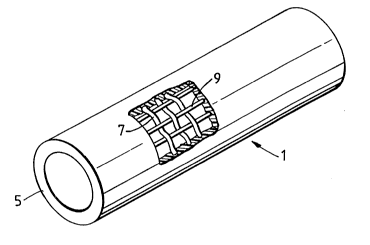
Figures 1 and 2 show a tubular article 1 which compri-
ses a fabric layer 3 and a matrix 5 of low density
polyethylene. The fabric layer 3 may for example
comprise 2 X 2 twill weave comprising a weft of heat-
shrinkable high density polyethylene fibres 7 extending
around the circumference of the article and a warp of heat-
stable fibres 9 extending along the length of the article.
The heat-stable fibres 9 comprise multifilament glass bundles
blocked with an ethylene vinyl acetate copolymer.
This is shown in more detail in the inset; multifilament
fibre 10, comprising filaments 11, can be seen to be blocked
by polymeric material 12.
Figure 3a shows a wraparound sleeve that may comprise a
fabric or composite embodying the invention. The sleeve
has closure means 14 (for example in the form of upstanding
rails 14 as illustrated), that may be held together for
example by a channel 15. An internal adhesive coating is
represented by crosses. Figure 3b shows the sleeve after
recovery.
Figure 4a shows a splice case comprising a sleeve 16
heat-shrunk around a splice 18 between two telecom-
munications cables 17, a centre portion having been removed
for repair or modification to the splice. End portions 19
can be seen to be left on the cables.
Figure 4b shows the re-entered sleeve of Figure 4a
resealed by means of an additional sleeve 20 shrunk over the
end portions 19 of the old sleeve. In general, a liner may
be provided underneath the original sleeve to act as a sup-
port to prevent the hot, shrinking sleeve damaging the cable
splice 18. It has been omitted from the drawings for
clarity.
1 3 3 5 7 5 ~ RK380
-28-
A leak-path along a longitudinal, generally heat stable
fibre in the original sleeve is shown as 21 in Figure 4b.
It can be seen to extend from the outside to the inside of
the splice case. Thus if the longitudinal fibres comprised
unblocked multifilament fibres, contaminants would be able
to enter the splice case by wicking along such fibres bet-
ween the filaments thereof. That is prevented by the fibre
blocking according to the invention. The invention may addi-
tionally or alternatively be used to block
circumferentially-extending multifilament recoverable
fibres.
Figures 5-11 il lustrate various forms of hybrid fibres
that may incorporate recoverable fibres, may be woven,
knitted or othewise fabricated into fabric, or may be com-
bined with a polymeric matrix material to form a composite
and/or recoverable material. Such a multi-layer material
may, particularly after heating, irradiation, pressurisation
and/or recovery be planar tight and be useful for providing
environmental protection around substrates such as those
comprising cables or pipes. After such heat, irradiation,
recovery and/or pressurization, the multi-filament bundles
shown will, in general, have the structure of fibre 10 of
Figure 2.
Figure 5 illustrates a multifilament fibre comprising
continuous strength fibres 22 and continuous heat-softenable
fibres 23 (shown dotted). The multifilament fibre may be
produced by co-mingling its components. The number of fila-
ments shown is less than that preferred. By "continuous" we
simply mean not staple fibre and do not imply any length
compared to the length of the bundle or to any fabric or
composite; nonetheless, we prefer fibres to be substantially
as long as the bundles, and the bundles to be substantially
1 335750
RK380
-29-
as long as the relevant dimension of the fabric or com-
posite.
Figure 6 shows in a transverse cross-section a core-spun
multifilament fibre, comprising a core of strength fibres 24
surrounded by a sheath of stable heat-softenable fibres 25.
The core may comprise a single, rather than a plurality, of
strength fibres. Such core-spun fibres may be made by the
Dref technique. "Dref" is a trademark of Fehrer AG of
Austria. We prefer that the core have a tex value of 2-300
preferably 15 to 30, more preferably about 22, and that the
core plus sheath have a tex value of 10-1000 preferably
75 to 150; more preferably about 100. Preferably the core
comprises glass and the sheath comprises short polypropylene
staple fibres. We have woven such core-spun fibres together
with heat-shrinkable high density polyethylene fibres and
lam nated the result with a low density polyethylene matrix
material. The core-spun fibres are preferably treated
before processing such as weaving or passage through nip
rolls or other equipment, in order to reduce their hairiness
or stickiness. Such treatment may comprise heating. This may
apply to other hybrid fibres referred to herein. The
resulting composite material was heat-shrunk by 5%, and then
tested for planar tightness, ie for its ability to resist
fluid passage along the glass core. It was found to be able
to resist fluid pressures of at least 80 psi for at least 15
minutes. This test may be regarded as demonstrating
excellent planar tightness for use of the composite in the
field of cable accessories and environmental protection in
general.
Planar tightness may in general be achieved without the
initial 5% recovery provided sufficient heat, irradiation
and/or pressure is applied to soften and/or deform the
~ 1 33575~
RK380
-30-
polypropylene or other blocking material provided as the
heat-softenable fibres. The extent of softening or defor-
mation required will of course depend on the nature (for
example size and number of filaments)of the strength fibres
and on the use to which the composite material is to be put.
Figure 7 shows a multifilament fibre bundle comprising a
hybrid of staple strength fibres 26 and staple heat-
softenable fibres 27 (shown dotted). It is preferred that
the strength fibres can transmit tension over a distance
greater than their own length, and they are preferably
intermingled with one another and not merely interconnected
by the heat-softenable fibres. Thus, the strength fibres
preferably constitute the greater part of the bundle.
Figure 8 shows in transverse cross-section a multifila-
ment fibre bundle comprising continuous strength fibres 28
surrounded by a polymer sheath 29 to the outside of which are
adhered staple heat-softenable fibres 30. A process for
making such hybrid fibres comprises Bobtex (Trademark)
integrated composite spinning. The polymer sheath may
comprise the same or a similar material to that of the heat-
softenable fibres.
Figure 9 shows in transverse cross-section a multifila-
ment fibre bundle comprising continuous strength fibres 31
and continuous heat-softenable fibres 32 running substan-
tially mutually parallel. The strength fibres preferably
comprise glass having a diameter of 3-30 microns preferably
6-12 microns and the softenable fibres preferably comprise
polyethylene, polypropylene or nylon 6 having a diameter of
5-15 microns. The bundle may be provided with some twist.
One or more bundles of strength fibres may be twisted with
one or more bundles of heat-softenable fibres, but we prefer
that the heat-softenable fibres be separated out throughout
1 335750
RK380
-31-
the strength fibres. Techniques such as ring twisting, 2
for 1 twisting, REPC0 (trademark) self-twist spinning and
flyer doubling may be used.
Figure 10 shows a multifilament fibre bundle formed by a
method that comprises wrap spinning (also known as hollow
spindle spinning) a core 33 comprising continuous strength
fibres and an outer coating 34 comprising heat-softenable
fibres, which may be held around the core by a wrap or
binder 35. The heat-softenable fibres may comprise staple
or continuous fibres.
Figure 11 shows a multifilament cable bundle being made
from four continuous fibres by cabling.
As mentioned above, it may be advantageous to subject
such hybrid fibres to a preliminary heat-treatment before
processing such as weaving (or other fabrication) or lamina-
tion etc. Such heat-treated fibres may be easier to process.
In the case of twisted hybrid fibres this may be due to con-
solidation or a reduction in the springyness or liveliness
of the twist, and in the case of core-spun fibres a reduc-
tion in hairiness may be achieved and the fibres may run
through machinery more easily, especially without sticking.
The following are specific examples of articles
according to the invention. In each case the article is in
the form of a uniform sleeve having a diameter of 30mm
before recovery, although sleeves of other sizes, and other
articles may of course be made.
Example 1
A 40 Tex pyrollised polyacrylonitrile yarn is twisted with
two ends of 30 Tex low melting point monofilament e.g. poly-
caprolactone. The resultant twisted yarn had a linear den-
~ 1 335750 RK380
-32-
sity of 110 Tex. The polycaprolactone melts at 55 degrees
centigrade.
Example 2
A 22 Tex glass fibre yarn is embedded within a sheath of
polypropylene staple fibre using core yarn production tech-
niques such as those associated with core spinning as an
example. The resultant yarn had a linear density of 50 Tex.
The polypropylene melts at 160 degrees centigrade.
Example 3
A 167 Tex Kevlar (TM) paraaramid yarn is wrap-spun
within a sheath of polyethylene terephthalate staple fibre
using a wrapping yarn of 17 Tex continuous multi-filament
polyethylene terephthalate yarn. The resultant yarn had a
linear density of 380 Tex. The polyethylene terephthalate
component of the yarn melts at 260 degrees centigrade.
Example 4
68 Tex glass multifilament fibres were impregnated
with various water-based latices as indicated below by
drawing them through a bath of latex and removing excess
latex. Water was removed by forced air drying. The latex
impregnated glass in each case was wound onto a spool and
later used for example to make a composite material, such as
a heat-recoverable composite.
Eatex Type
1. Ethylene Vinyl acetate copolymer
2. Ethylene vinyl acetate/butyl acrylate terpolymer
3. Chlorosulphonated polyethylene
4. Carboxylated styrene butadiene copolymer
1 335750
RK380
-33-
Example 5
34 Tex multifilament glass fibre which had previously
been impregnated from the melt with ethylene vinylacetate
copolymer (28% vinylacetate) was used as described to make
fabric for use in composite constructions for example a heat-
recoverable composite construction.
Example 6
68 Tex multifilament glass fibre was impregnated with a
liquid composition containing a polymeric precursor which was
polymerized in situ, with the aid of U.V. radiation, to give
a solid polymeric impregnant. Impregnated glass was used to
make fabric for use in composite constructions such as heat-
recoverable composite constructions.
.
Example 7
68 Tex multifilament glass fibre was impregnated with a
solution of ethylene ethyacrylate copolymer (25% ethyl acry-
late) in toluene at 80C, the excess solvent being driven off
by forced air drying. The resulting blocked glass was wound
onto a spool for subsequent use, for example the production
of fabric for inclusion in a glass-based composite.
Example 8
The hybrid fibres of examples 1-3 were woven and the
resulting weave was laminated with a layer of low density
polyethylene, and the resulting composite was hot-
compressed to simulate the conditions that a recoverable
composite comprising such fibres would experience on
installation.
200mm length of the resulting composites with the glass
fibres vertical and the lower edge freshly cut were dipped
~ 1 335750
RK380
-34-
to a depth of 10mm in an aqueous solution of methylene blue.
After 24 hours at room temperature lengths of glass were
checked to determine distance of travel of the methylene
blue solution along the glass (wicking). The following table
notes the distances measured.
Glass unimpregnated (comparision) 33mm
Examples 1 to 3 minimal
Example 9
The hybrid fibres of examples 4-7 were woven and the
resulting fabric was laminated. 200mm of the resulting com-
posites with the glass fibre vertical and the lower edge
freshly cut were dipped to a depth of 10mm in an aqueous
solution of methylene blue. After 24 hours at room tem-
perature lengths of glass were checked to determined
distance of travel of the methylene blue solution along the
glass (wicking). The following table notes the distances
measured.
Latex 1 ( as Example 4) 1.1mm
2 ( " " 4) 1.0mm
3 ( ~ 4) 1.7mm
4 ( " " 4) 0 mm
Ethylene vinyl acetate (as Example 5) 10 mm
U.V. Cured acrylic (Example 6) 1.1mm
Ethylene ethylacrylate (Example 7) 4.4 mm
The impregnations can be seen to have a significant
effect on liquid uptake. A wicking distance of 10 mm or
less more preferaby 5 mm or less is preferred.
Example 10
Multifilament fibres as described in Examples 1-7, were
woven into a fabric as disclosed above and were laminated
~ 1 335750
RK380
-35-
with low density polyethylene, for example by extrusion
coating to form a composite structure. This was formed into
a heat-recoverable splice case according to known tech-
niques.
A sleeve produced as described was recovered over a
cable splice as shown in Figure 3b. In order to reenter the
enclosure a central portion of the splice case was removed by
making two circumfential cuts through it, one at each end of
the splice thus leaving the end portion in position on the
cables (Figure 4a). A second sleeve was recovered over the
old end portions thus bridging the splice (Figure 4b).
After allowing the splice closure to cool it was sub-
jected to an internal pressure of 100 KPa for 15 minutes
while submerged in water. No air escaped from the closure thus
indicating a perfect seal around the splice. No air was able
to leak away via the multifilament glass fibres impregnated
as defined above.
This was followed by a temperature cycling test. The
closure was internally pressurized to 40 KPa and isolated,
ie maintaining a pressure of 40 KPa at room temperature,
variable as a function of temperature. The enclosed splice
was subjected to a temperature cycle of -30 to +60C, one
complete cycle being twelve hours. No pressure loss was seen
after completion of 15 cycles.
For comparision, the above procedure was repeated, but
using a heat recoverable splice case made using 68 Tex glass
with no blocking material present. Upon reentry and reclo-
sure and subsequent pressurization, air was seen to leak
profusely via the ends of the multifilament glass. Similar
air leaks were seen at the onset of temperature cycling.
1 335750
RK380
-36-
For the avoidance of doubt, it is noted that the inven-
tion provides various methods, composites and recoverable
articles that are blocked or planar tight, or that any one
or more of the fibres, fabrics, articles, composites, and
blocking materials and methods may be selected. Also, any
combination of the various features defined in the various
claims may be combined.