Note: Descriptions are shown in the official language in which they were submitted.
3~7~5
GAS-FIRED RADIANT BURNER
The present i~lv~rl~ion relates to a gas-fired radiant
burner for emitting infrared heating radiation, the burner
including a plenum chamber into which an air-gas mixture is
injected from a mixer, with one of the faces of the body
ting the pl~nllm ~h~Pr being constituted by at least one
combustion support on which combustion of the air-gas mixture
takes place, thereby r~ing the surface of said support to a
high temperature c~ ; ng the support to radiate.
Industrial pr~mi~e~ or premises receiving the public may
be heated by various techniques including, in particular,
convection heating and radiant heating.
Radiant heating may be performed, in particular, by means
of bright radiant panels constituting emitters and charac-
terized by external combustion taking place on a ceramic sur-
face which is raised to a high temperature. This surface is
made up of ceramic plates or "tiles" perforated by multiple
small diameter orifices. Combustion of the air-gas mixture
(generally provided by an atmospheric induction mixer) begins
close to the outlets of the orifices, thereby raising the
surface of the tiles to a high t~m~ature. These apparatuses
having high unit power are generally used for heating
industrial premises which are very tall and poorly insulated.
Apparatuses of this type suffer from drawbacks insofar as the
combustion products from the radiant panels are exhausted into
the premises being heated. A high degree of condensation can
th~n take place if the premises are sufficiently draught-proof.
Further, legislation in various countries does not allow
apparatuses of this type to be used in premises receiving the
public because of safety reasons related to the combustion
products being exhausted into the premises being heated.
Low temperature radiant tubes are also known which are
characterized by internal combustion. A gas burner provides
combustion products which flow inside a tube which is raised to
a relatively low temperature. This tube radiates and the
radiation is directed by means of a reflector placed above the
tube. An extractor fan sucks up the combustion products which
2 133 S7 8
may be exhausted inside or outside the premises being
heated. A drawback of such apparatuses lies in the fact
that their operating temperatures are relatively low
which means that such apparatuses can be installed only
in premises of average height.
One of the operating characteristics of radiant
heaters i5 their radiation efficiency, i.e. the ratio of
the power radiated to the power supplied. The radiation
efficiency of bright radiant panels may be as much as
60%, whereas low temperature radiant tubes have lower
radiation efficiency, of the order of 50%.
The present invention in one aspect seeks to remedy
the above-mentioned drawbacks and to provide a radiant
burner which, like radiant burners having perforated
ceramic tiles, presents high unit radiated power, thereby
enabling it to be placed in tall premises, but which does
not present the drawbacks of said type of apparatus, i.e.
in particular, it does not exhaust combustion products
into the premises being heated.
An object of an aspect of the invention is to
provide a radiant burner capable of operating at a higher
temperature and with higher radiation efficiency than
radiant tubes.
An aspect of the invention is as follows:
A gas-fired radiant burner for emitting infrared
heating radiation, the burner comprising a body having a
plenum chamber into which an air-gas mixture is injected
from a mixer, with one of the faces of the body
delimiting the plenum chamber being constituted by at
least one combustion support on which combustion of the
air-gas mixture takes place, thereby raising the surface
of said suppor~ to a high temperature causing the support
to radiate, a device for recovering the combustion
products comprising a recovery chamber surro~ln~i n~ the
plenum chamber and delimited by a gas-tight body whose
wall parallel to the combustion support includes at least
one gas-tight plate made of a material which transmits at
C
~ 133578~
least a substantial portion of the infrared radiation and
capable of withstanding high temperatures, and a flue for
extracting the combustion products present in the
recovery chamber, the burner further comprising a heat
exchanger between the combustion products and the
oxidizing air, said heat eYch~qer including an
additional chamber which surrounds the combustion product
recovery chamber in gas-tight manner except for the face
constituted by the radiation-passing gas-tight plate,
with the oxidizing air passing through said additional
chamber, and with said additional chamber being put into
communication with the air-gas mixing zone of the mixer.
The walls delimiting the recovery chamber and the
additional chamber are made of a material which is a good
conductor of heat in order to facilitate the heating of
the oxidizing air passing through the additional chamber
by means of the combustion products present in the
recovery chamber.
The gas-tight plate is preferably made of a glass
ceramic based material which may advantageously be
translucent or transparent.
The combustion support may be constituted by a
porous refractory material or by refractory ceramic
tiling which is pierced by multiple small-diameter
orifices.
Advantageously, the radiant burner further includes
a confinement screen disposed parallel to the surface of
the combustion support on its side opposite from the
plenum chamber in order to improve heat exchange between
the flame and the support.
The confinement screen may be embodied in various
different ways.
In a first embodiment, the confinement screen is
constituted by a metal screen made of refractory steel in
the form of a large-mesh grid.
In another embodiment, the confinement screen is
.~
~ 3a 133578~
constituted by a latticework of rods.
In another embodiment, the confinement screen
comprises a ceramic plate.
The walls delimiting the plenum chamber and the
recovery chamber, other than the radiation-passing gas-
tight plate and the optional confinement screen are made of
a material which is a good conductor of heat in order to
facilitate heating the air-gas mixture contained in the
plenum chamber by the combustion products present in the
recovery chamber.
~2
~ 133578S
As a result, a radiant burner in accordance with the
invention avoids the major drawbacks of radiant panels and
of radiant tubes while still retaining the advantages of
each of these types of equipment, namely:
5high unit radiated power, thereby making it possible
to use the apparatus in premises which are very tall;
the combustion products can be exhausted in a
controlled manner, thereby preventing them from being
diluted in the atmosphere of the premises or the enclosure
10being heated; and high radiation efficiency by virtue of
the ease with which the heat lost by the combustion
products can be recovered.
A radiant burner in accordance with the invention is
suitable for heating enclosures such as ovens, drying
15rooms, etc. and also for heating large-volume premises such
as workshops, factories, exhibition halls, or sales halls.
Other characteristics and advantages of the invention
appear from the following description of a particular
embodiment given by way of example and with reference to
20the accompanying drawing, in which:
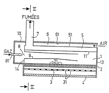
Figure 1 is an axial section through a gas-fired
radiant burner in accordance with the invention; and
Figure 2 is a cross-section on line II-II of Figure 1.
The example of a radiant burner in accordance with the
25invention which is shown in Figures 1 and 2 comprises a
plenum chamber 1 into which an air-gas mixture is injected
by means of a converging-diverging nozzle 9 disposed
horizontally, said mixture being provided by an atmospheric
induction mixer. The nozzle 9 accelerates the air-gas
30mixture and improves the quality of mixing. The mixer is
essentially constituted by a pre-mixing zone 8 into which
the gas is injected by an injector 81 which opens out
horizontally and which lies on the axis of the nozzle 9
facing the inlet thereto. The oxidizing air is itself
35injected into the pr~r;x;ng zone 8 after flowing along an
additional outer chamber 6 in contact with the wall 51, 52
of the chamber 5 for collecting the combustion products,
thereby preheating the air.
The plenum chamber 1 into which the nozzle 9 opens out
40is delimited by a substantially horizontal top wall 11, two
B
1~ 5 1335785
vertical side walls 12 extending in the longitudinal direction
of the burner on either side of the nn~ ., a vertical end wall
13 f~i ng the outlet from the nozzle 9, a vertical end wall 14
through which the air-gas mixture in;ection nozzle 9 is
mounted, and a substantially horizontal bottom face 2. The
~oL~.. face is constituted by one or more refractory ceramic
tiles 2 pierced by multiple small-dia~,e~el orifices 21 with
com.bustion of the air-gas mixture taking place at the outlets
of the orifices, thereby raising the surface of the tile(s) 2
to a high temperature c~ ing the tile(s) 2 to radiate.
A screen 3 in the form of a large mesh grid 31 made of
stainless steel is disposed parallel to and beneath the tile(s)
2, i.e. adjacent to the face looking away from the plenum
~hamb~r 1. The screen 3 confines combustion and provides
i~ ~v~d heat exchange between the hot gas and the ceramic
tile(s).
The com.bustion products that pass through the screen 3 are
pl~v~lted from escaping into the premises being heated by vir-
tue of a glass ceramic plate 4 forming a gas-tight barrier
which is placed beneath the screen 3 and at a distance
therefrom, and is preferably parallel to the screen 3.
Vertical side walls 52 extend in the longitudinal direction of
the burner outside the side walls 12 ~elimiting the plenum
ch~m~P-r 1 containing the air-gas mixture, and at a distance
from said walls 12. A top horizontal wall 51 extends horizon-
tally over the top horizontal wall 11 of the plenum chamber 1
at a distance therefrom. This forms a recovery chamber 5 for
recovering the combustion products and surrounding the plenum
chamber 1, with said recovery chamher 5 being ~Ql im;ted by a
set of gas-tight walls (walls 51, 52, and vertical extensions
of the end walls 13 and 14 of the plenum cham.ber 1) and the top
of the recovery chamber 5 is in com.munication with a flue 7 for
extracting the combustion products present in the recovery
~h~mh~ 5.
The com.bustion products are thus channelled through a
recovery chamber 5 of the double-walled type which includes
walls 11 and 12 for exchanging heat with the air-gas mixture in
6 133~
the plenum chamber 1. The combustion products thus give a
portion of their energy to the air-gas mixture, thereby
~o.l~libuting to i~ uving ef~;r;~nr.y.
The "triple-walled" type configuration shown in Figures 1
and 2 with an additional outer chamber 6 for ~ollv~ying the
~xi ~i ~i ng air and including heat exchange walls 51 and 52 for
~xrh~ng~ng heat with the combustion products in the recovery
chamber 5 serves, addi~ion~lly to preheat the oxidizing air.
The side walls 62 and the top wall 61 of the nxi~i ~ing air
inlet chamber 6, and also the end walls of the burner (situated
to the right and the left of Figure 1) may be coated internally
or extern~lly with thermally insulating material in order to
reduce heat loss via these outer walls of the apparatus.
The heat provided by the radiant burner is thus
transmitted almost exclusively through the glass ceramic plate
4 which, in addition to constituting a barrier for the combus-
tion products also relays the radiation emitted by the tile(s)
2 efficiently. The plate 4 is made of a glass ceramic based
material and is preferably transparent or translucent.
Apparatus in accordance with the invention can thus
radiate a large amount of power by virtue of its high operating
t~m~Prature made possible by using a plate of glass ceramic
material or the like which is capable of withstanding high
t~mreratures while passing radiation.
Further, the radiation efficiency of the radiant burner is
high since the energy lost to the PXh~ t is easily recovered
by means of the double-walled envelope and since the ~xh~ t is
not diluted with ambient air.
A radiant burner of the invention may be used for heating
premises and may deliver power lying in the range about
100 kW/m2 to 150 kW/m2 of radiating ceramic tile area
giving rise to a ceramic tile ~"~euature of about 900C with
radiation efficiency of about 60%.
The radiant burner may also be used in like manner for
heating enclosures (ovens, drying rooms, etc.) in which case it
may deliver power at more than about 150 kW/m2 of radiating
ceramic tile area giving rise to a ceramic tile temperature of
about 1100C with radiation efficiency of about 55%.
7 133~785
Various mo~;f;~Ations and additions may be applied to the
~o~;m~nts described with reference to Figures 1 and 2.
Thus, in the event that the oxidizing air and exhaust heat
exchanger (walls 51, 52) gives rise to too much p~e~sure-drop in
the air supply circuit, an nX;~; ~;ng air fan may be added in
order to co-operate with the premixing chamber 8 of the mixer
and/or an extractor fan may be added to facilitate the
extraction of combustion products via the flue 7.
The nozzle 9, and the heat exchange walls 11, 12 or 51, 52
of the double- or triple-walled enclosure may be made of
st~; n 1 e~s steel, for Rxample.
In a variant, the co-mbustion support 2 may be made of a
porous refractory material.
The confinement screen 3 may also have configurations
other than that described with reference to Figures 1 and 2.
Thus, the screen 3 may be constituted by a lattice of rods or
by a gas-passing ceramic plate or even, in some cases, by a
metal grid having relatively small mesh size.
Further, it has been assumed above that the bright radiant
face 4 of the radiant burner is placed beneath the burner and
is horizontal. Naturally, the burner assembly may be tilted in
order to direct its radiating face in a direction which is to
receive most heat. In most cases, the radiating face 4 is
either horizontal or else inclined to form an angle with the
horizontal which is less than about 60. The burner is still
capable of operating with its radiating face in a vertical
position, however its efficiency is likely to be slightly
reduced in comparison with operation having the radiating face
horizontal or inclined at less than 60 relative to the
horizontal.