Note: Descriptions are shown in the official language in which they were submitted.
-
1 3359~2
a -
CUTTING BRITTLE MATERIALS
This invention relates to a method and apparatus
for cutting brittle materials, and in the preferred
embodiment provides a method and apparatus suitable for
cutting ceramic tiles and toughened glass.
Ceramic decorative tiles, including floor tiles
of the "quarry" type, and toughened glass, are
conventionally cut by scoring a line on the surface to act
as a stress concentrator, and then bending the workpiece
across a suitable edge to cause the material of the
workpiece to fracture along the scored line.
This technique suffers from a number of
disadvantages. Firstly, if the surface of the item to be
cut is very hard it is difficult to form a continuous score
line. Even if such a line can be formed, it is difficult
to form a curved line accurately and accordingly curved
cuts are difficult to make. Also, the technique does not
always result in a clean break even when a continuous line
has been scored. Finally, very large forces are necessary
in order to apply sufficient bending moment to relatively
thick tiles of the type used for flooring.
A brittle material allows stress to rise to
breaking point without yielding - the stress being relieved
by final fracture. If fracture of the lattice occurs as
the result of a single impact or a sustained pressure, its
1 335902
effect would only be apparent if the induced stress were
sufficient to cause a crack to penetrate through the
full thickness of the workpiece. This offers little or
no control of the direction or extent of crack
propagation. If, however, the stress is applied as a
combination of short impulses and steady direct stress,
the breaking stress of the material would be attained
coincident with the peak oscillatory stress. Crack
propagation would therefore proceed by a series of
stepwise fractures induced by successive cyclic stress
peaks, resulting ultimately in the separation of the
workpiece into two pieces.
It is an object of one aspect of the present
invention to utilize this discovery to provide a method
and apparatus to cut hard fully vitrified and glazed
floor tiles, quarry tiles and marble, as well as float
glass and special decorative glass. The technique may
even be extended to cut and shape concrete products and
a range of ceramic and vitreous china materials.
Accordingly, this invention provides a method
of cutting a workpiece of brittle material into two
pieces along a predetermined line comprising producing a
micro crack in said material by applying directly
to the surface of the workpiece at a point on
said line the pointed end of a tool, applying high
frequency vibrations in a longitudinal direction to the
tool while applying substantially steady longitudinally
directed pressure from the tool to the workpiece until
said micro crack occurs, moving said tool along said
line to propagate micro cracks in said workpiece along
the length of the line, and then breaking said workpiece
along said line into two pieces.
Preferably the vibrations applied to the tool
are of a frequency in the region of 8 to 35 kHz.
Where the brittle workpiece is a ceramic tile,
a preferred frequency is in the region of 30 kHz.
, ., .~ ~
3 1 335~2
Where the brittle workpiece is a concrete
product, the preferred frequency may be in the region of
10 kHz.
The line to be cut may be linear, curved or
contain abrupt changes of direction, e.g. through a
right angle.
Advantageously, the high frequency vibrations
applied to the tool are derived from ultrasonic
vibrations of a piezoceramic transducer.
In a further aspect, there is provided a tool
for cutting a workpiece of brittle material into two
pieces along a predetermined line by producing micro
cracks in said material along said line comprising
pointed tip means constructed and arranged to be applied
to the surface of a workpiece, said tip means having a
hardness greater than said workpiece, piezo electric
ceramic transducer means to generate in said tool
ultrasonic vibrations, means for applying substantially
steady longitudinal pressure from said tool through said
tip means to a workpiece, and means for conveying the
ultrasonic vibrations generated by said piezo electric
ceramic transducer means in a longitudinal direction to
said tip means while pressure is applied to a workpiece
by said substantially steady pressure applying means.
The means to convey the ultrasonic vibrational
energy to the tip means is preferably a tuned horn.
The tip means may be of tungsten carbide or
other material of equivalent hardness.
In one preferred version, the tip means may
comprise a core of comparatively hard material and an
annular sleeve of material which is comparatively soft
but still harder than the material of the workpiece.
In this case, the core may have a diameter of
lmm and the sleeve an outer diameter of 3mm. The
combination tip may have a length of 7mm.
3a 1 335902
In order to transmit the vibration to the tip,
it may be fixed within a holder of e.g. stainless steel.
Embodiments of the present invention will now
be more particularly described by way of example and
with reference to the accompanying drawings, wherein:
FIGURE 1 is a schematic representation of
crack propagation in a workpiece;
FIGURE 2 shows, in longitudinal cross section
an apparatus embodying the invention;
FIGURE 3 shows an alternative embodiment of an
apparatus, having a stepped output end;
-
_ 4 - 1335902
FIGURE 4 shows schematically an electronic drive
circuit for an apparatus embodying the invention;
FIGURE 5 is a cross-sectional view of an
apparatus embodying the invention and a housing therefore;
and
FIGURE 6 shows the apparatus of Figure 5 and a
ceramic tile cut by the apparatus.
Referring now to the drawings, Figure 1
illustrates schematically the mechanism by which the method
embodying the invention works. At the top of the Figure is
shown the cyclic stress pattern applied by the tool to the
workpiece by virtue of high frequency vibrations imparted
to the tool With each peak of the stress pattern, a short
downward impulse is applied to the workpiece, this impulse
being additional to the substantially steady stress being
applied thereto, either simply by virtue of the weight of
the apparatus or by virtue of downwardly directed manual
pressure. (In this connection manual pressure may be taken
to include pressure applied by a human hand or by an
operative part of a robot or machine.)
Each short impulse raises the total stress on the
workpiece instantaneously to the breaking stress of the
material and therefore crack propagation begins and
increases with each peak. This is shown schematically at
the foot of the Figure. Ultimately the workpiece will
break along a line transcribed by a tip of the apparatus.
It is possible with a hand held tool to define a
path in which such microcracks are generated, using a sharp
pointed vibrating tip initially to score the surface of the
workpiece. Subsequent movement of the tip back and forth
along the prescribed path results in fracture within 4-20
secs. depending on the type of material and the workpiece
thickness.
- 5 -
1 335902
Figures 2 and 3 show examples of ultrasonic
systems suitable for generating high stresses in hard
brittle materials.
In each case the system comprises a sharp tip 1
of hard material, for example tungsten carbide or even
diamond, in a stainless steel holder 2. This assembly is
screwed, by means of threaded shank 3, into a tuned horn
connected to a transducer 4 operatively connected with
piezoelectric ceramic rings 5.
In the embodiment of Figure 2, the total length
of the apparatus is one wavelength, while in the embodiment
of Figure 3, which shows a transducer with stepped output
end, the total length is one half of a wavelength.
One problem which may be encountered is that the
tip may become blunted after repeated use. It is possible
to resharpen it but it is difficult since the tip is of
hard material. In one embodiment, the tip is a composite
having a 1mm diameter core of a hard grade of material
within a 3mm diameter outer sleeve of comparatively shoft
material. (By "comparatively soft" is meant softer than
the core but harder than the material of the workpiece.)
With this construction, the sleeve will wear down
preferentially, leaving a reasonably sharp tip.
The successful operation of such systems will
depend on the ability to maintain mechanical resonance in
the cutting tip 1 under all loading conditions. The
generator output frequency must therefore change to
compensate for frequency shifts due to variations in tip
length and workpiece characteristics. Figure 4 shows a
schematic circuit for achieving this. The power supply 6
provides DC voltages to the output 7 and resonant drive
8 circuits. The switch mode output is driven by a VCO
(voltage controlled oscillator) with pT-T. (phase locked
loop) frequency control using a signal derived from the
output current.
- 6 - ~ 3 3 5 9 0 2
The invention has been described with reference
to the necessary high frequency vibrations being producedby
piezoceramic transducer systems. However the impulsive
forces used to generate the cyclic stress can be produced
by several means; viz. an ultrasonic transducer with tuned
horn and cutting tip; an electromagnetic vibrator
(frequency limit around 10 kHz); by mechanical means,
using a cam; or hydraulically. The feature common to each
excitation system is that it must operate at a high
frequency, in the order of several kHz. It is believed
that better control of the rate of crack propagation is
achieved the higher the frequency. For example when
cutting floor tiles which are typically 8-1Omm thick,
adequate control is provided by an ultrasonic system
operating at 30 kHz. In concrete products where the stress
is relieved by the presence of numerous internal voids in
the structure, crack propagation would be much slower and
consequently a lower frequency would be expected to provide
adequate control e.g. around 10 kHz.
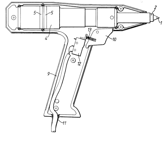
Referring now to Figures 5 and 6, there is shown
an apparatus embodying the invention. The vibration
generating and transmitting apparatus is essentially as
described above. It is housed in a pistol type casing 9
with a trigger 10 for allowing connection between a RF
input 11 and the piezoceramic transducer. The trigger 10
acts on a microswitch 12 which can operate a relay in the
frequency converter unit. The trigger 10 is biased
outwardly by spring 13 so that a positive action is
required for the cyclic stress vibration to be set up.
An external view of the tool of Figure 5 is shown
in Figure 6, together with a ceramic tile cut by the tool.
As can be seen, the cut made need not necessarily be
linear, as is generally the case with existing tile cutting
methods, but may be curved and, in fact, may include abrupt
changes of direction. By generating the crack over several
impulses of the tip, the crack may increase in depth
stepwisely until the workpiece breaks.