Note: Descriptions are shown in the official language in which they were submitted.
-1- 1 336058
S P E C I F I C A T I O N
BACKGROUND OF THE INVENTION
Pield Of The Invention
This invention relates to surgical implants and more particularly, to
05 surgical procedures and appliances for intraarticular anterior and posterior ligament
reconstruction .
Prior Art
It is well known by anyone who has participated in athletics that the
human knee is injury prone, particularly from lateral forces applied thereto. Where
the knee joint is considered by most laymen to be essentially a hinged joint, in reality
it provides a complicated mechanical movement that would be nearly impossible toduplicate with present technology. In operation, the human knee joint permits
movement of flexion and extension in certain positions and even provides for a slight
inward and outward rotation. Considering only movement of flexion and extension,the mechanical actions that take place in such movement include a certain amountof gliding and rotation along with the hinge action such that the same part of one
articular surface of the distal femur or proximal tibia will not alwHys be applied to
the same part of the other articular surface, and the axis of motion is not fixed.
In fact, if the knee joint is examined while in a condition of extreme flexion, the
posterior part of the articular surfaces of the tibia will be found to be in oontact
with the femur posterior around the extremities of the condyles. Whereas, if themovement was simple hinge like movement, the axis around which the revolving
movement of the tibia would occur should be in the back part of ~he condyle. With
the same leg brought forward into a position of semi-flexion, the upper surface of
the tibia will seem to glide over the condyle of the femur, such that the middle part
of the articular facets are in contact, and the axis of rotation is therefore shifted
forward to near the center of the condyle. When the leg is brought into the
extended position, still further gliding takes place as does a further shifting forward
of the axis of rotation. Knee joint flexure and extension is therefore not a simple
~vP cnt but is accompanied by a certain amount of outward rotation around a
vertical axis drawn through the center of the head of the tibia. This rotation is due
,~
- 1 3~6~
-- 2--
to the greater length of the inte. nal condyle, and to the fact that the anterior
portion of its srticular surface is inclined obliquely outward. In consequence, towards
the close of the movement of extension, just before complete extension, the tibia
will glide obliquely upward and outward over the obl.que surface of the inner condyle,
05 and the leg will be necessarily rotated outwardJy. In flexation of the joint, the
converse of these movements takes pluce, the tibia gliding backwardly around the
end of the femur, at the commencement of which movement, the tibia is directed
downward and inward along the oblique curve of the inner condyle, thus causing an
inward rotation to the leg.
The above sets out a brief summary of knee joint functioning that takes
place in knee flexure and extension. It is provided to show that this functioning is
far more than a hinge movement and involves inward and outward rotation. It should
be apparent therefore that in a repair of one or more ligaments of the knee,
particularly in an intraarticular anterior and posterior ligament reconstruction that
involves the cruciate ligaments, it is of significant value that the replacement
ligaments, either a graft or prosthetic ligament, be fitted so as to, 8S nearly as
possible, duplicate the positioning of the natural ligament. Heretofore, procedures
and devices for use in repairing damaged ligaments, particularly the cruciate ligaments,
have generally involved attaching the ligament device across the knee at the juncture
of the distal femur and proximal tibia surfaces. Where sn attempt has been made
to replace a cruciate ligament that involves securing the replacement ligament ends
to the points on the opposing bone surfaces where that natural ligament was attached,
such procedure has involved extensively opening the patient's knee area and/or
forming intersecting tunnels through the respective tibia and femur ends and
positioning a ligament therebetween. An example of such surgical technique and an
implant device is shown in a patent by Hunt, et al., U.S. Putent No. 4,590,928. This
p~tent is directed to an implant and kit therefore but does not, as does the present
invention, provide an arrangement that is a near duplication for the patient's natural
ligument. Rather, the Hunt, et al. patent is devoted to connectors and an implant
that incorporates carbon fibers and, where tunnels are shown formed in the respective
bones, such are apparently formed where access is convenient. As the tunnels are
not aligned and each is open to without the femur and tibia surfaces, their formation
involves extensive opening of the knee to provide access to the bone surfaces.
1 336058
Unlike the Hunt, et. al. patent procedure, the present invention provides for ligament
reconstruction using essentially an arthroscopic technique where a single incision
only is made to the bone below the tibia tuberosity. From that point, a tunnel is
formed into the bone that passes through the respective points of connection of a
05 cruciate ligament between the proximal tibia and distal femur and into the femur
cortex. The femur cortex is then prepared to receive a ligament end coupling fitted
therein to secure one ligament end.
Earlier ligament replaccment procedures have involved an extensive
opening of the knee and have included forming passages or tunnels in the tibia and
femur from the bone surfaces wherethrough are pulled a natural or artificial ligament,
the ends of which ligament are bent and secured as with staples to the bone surfaces.
Unlike such earlier procedures and arrangements, the present invention provides for
both fitting a ligament to extend across the knee so as to most nearly duplicatethe natural ligament positioning and provides for internal coupling the one ligament
within a bone cortex. Additionally, the present invention provides a convenient
I . g~ ~nt for adjusting the implanted ligament tensioning to most nearly duplicate
a natural condition. The present invention therefore provides both a unique surgical
a~r.ach and attachment devices to produce and implant that most nearly duplicates
the patient's natural ligament arrangement than has heretofore been possible.
BRIEF SUMMARY OF THE INVENTION
It is therefore a primary object of the present invention to provide an
arthroscopic system or technique for replacing with an allograft or prosthetic ligament
a ruptured ligament of the knee, preferably a cruciate ligament.
It is another object of the present invention to provide an arthroscopic
procedure that employs a single incision only that is made medial to the pstient's
tibial tuberosity and at this point tunneling through the bone, across the distal femur
and proximal tibia surfaces and into the femur cortex, the tunnel to pass through
the points of connection of the ligament ends to the bone of either the anterior or
posterior cruciate ligament.
3 0 It is another object of the present invention to provide for forming the
tunnel to end in the femoral cortex just beyond the medullary channel and to prepare
it to receive a connector that is turned or expanded therein so as to positively lock
a ligament end within that bone cortex.
~4~ 1 336058
;~ It is another object of the present invention to provide a procedure for
tunneling through the patient's tibia across the proximal tibia and distal fem ur
surfaces and into the femur cortex that involves opening the patient's knee at a
single point or location only on the tibial tuberosity and for closely controlling the
05 tunnel formation process through a use of fluoroscopic and/or arthroscopic procedures
to form a passage that is essentially straight and intersects the connection points
of the ruptured cruciate ligament on the bone surfaces so as to receive an allograft
or prosthetic ligament that is fixed on one end within the femur cortex and extends
from the tunnel end at the tibial tuberosity.
Still another object of the present invention is to provide an end coupling
for the prosthetic ligament to secure it at the tunnel entrance at the tibial tuberosity
and adjusting the ligament tensioning,
Still another object of the present invention is to provide a surgical
procedure for replacing a torn or damaged cruciate ligament with an allograft or
prosthetic ligament that requires minimal patient trauma and minimizes the time
required for healing.
Still another object of the present invention is to provide an allograft
or prosthetic ligament for replacement of a ruptured or damaged ligament that
includes connectors made of a biodegradable material for maintaining the ligament
2 0 in place and will be absorbed by the body in the healing process.
In accordance with the above objects, the present invention is in an
arthroscopic surgical procedure for installation of an allograft or prosthetic ligament
as a replacement for a ruptured knee ligament, preferably either an anterior or
posterior cruciate ligament. In a practicc of the procedure, a patient's lower leg
is maintained in approximately a ninety degrec (90) angle to their upper leg and a
longitudinal incision is made medial to the tibial tuberosity, which incision is made
to the bone. At that incision, a stainless steel guidewire is driven in the anterior
medial tibia at a point that is approximately two (2) centimeters distance to the
medial tibial plateau. Guidewire insertion is conducted under fluoroscopic and
arthroscopic control. The guidewire, after insertion, is thereby visualized as it is
forced through the joint of the distal femur and proximal tibia, crossing the
intercondylar notch area of the knee to engage the posterior and lateral femoral
condyle. The preferred point of femur entry is deep within the intercondylar notch,
~5~ 1 3 3 6 ~ ~ ~
ss identified under fluoroscopic visualization, approximately four (4) millimeters
anterior to the junction of the femur posterior cortex and the intercondylar seam
as would be seen in a true lateral x-ray film of the distal femur. Guidewire travel
is continued to pass through the femur cancellous bone, the medullary channel and
05 into the anterior lateral cortex so as to be just proximal to the metaphysical flare
of the distal femur. So instaJled, the guidewire is then used to direct drill points
of increasing drill sizes along its course, the drilling operation to sequentially increase
the passage or tunnel diameter from the tunnel entry at the tibial tuberosity.
In the passage or tunnel formation the increasing size drills are stopped
in the medullary channel. As a final step in the tunnel formation, the tunnel end
is drilled beyond the medullary channel into the femur anterior cortex where theguidepin has been lodged. This final hole is made in preparation for turning either
a tap therein forming threads or a flaring drill to widen that tunnel end. In one
embodiment the ligament femoral end connection is a threaded component to be
turned into the threaded tunnel end. In another embodiment the ligament femoral
end connector is arranged to be exrpnrled or outwardly flared to fill the widened
tunnel end.
After tunnel formation, the ligament is inserted to where its end is
secured in the femur cortex as by either turning or expanding the connector end
therein. The ligament thereby extends from its cortex end to where it exits the
tunnel at the tunnel point of entry on the tibial tuberosity. Where the ligament is
an allograft, the ligament end can be bent at the tunnel end ucross the bone andstapled thereto. Where the ligament is a prosthetic ligament, a preferred end
coupling involves forming threads in the ligament end to receive a flat disk that is
2 5 center tapped and slopes outwardly from one face to the other around the
circumference, the small diameter face to nest in the tunnel end. This connectorarrangement provides a capability for ligament length adjustment to achieve a desired
ligament tensioning. In both embodiments, the respective connectors can be formed
of a biodegradable material, such as a polylactic acid that will be absorbed by the
body during the healing process, the bone growing to either the prosthetic or allograft
ligaments.
- -6- ~ 336058
Utilization of the above-described ligament and preferred connector
installing procedure provides for ligament positioning to most neurly duplicste a
damsged ligsment snd for setting a desired tensile stress in the ligament.
DESCRIPTION OF THE DRAWINGS
05In the drawings thst illustrste thst which is presently regarded as the
best mode for carrying out the invention:
Fig. 1 shows a pstient's leg with their lower leg muintained at
spproximately a ninety (90) angle to the upper leg, which positioning is to be
maintained throughout a surgicsl procedure of the present invention;
10Fig. 2 is an enlarged side elevation view exposing the proximal tibia and
distsl femur ends of the leg of Fig. 1, which distsl femur is shown as hsving hsd
a section removed to the bone cortex, exposing a tunnel formed therein tllat contains
one embodiment of a prosthetic ligament and end connectors therefore of the present
invention;
15Fig. 3 is a front elevation view of the distal femur and proximal tibis
ends of Fig. 2 showing a portion of the femur cortex removed exposing the tunnelwith the prosthetic ligsment end secured therein;
Fig. 4 shows sn enlsrged side elevstion view of the prosthetic ligsment
of Figs. 2 and 3 removed from the pstient's knee, and shows the ligsment femorsl2 0and tibisl sttschment ends ~s they sppesr before instsllstion;
Fig. SA is an enlsrged end view of the femoral sttschment end of the
prosthetic ligsment of Fig. 4;
Pig. SB is a view like Fig. 5A except that it shows the femoral attschment
end having been eyppn~led to the flared configuration shown in Figs. 2 and 3;
25Fig. 6 shows another embodiment of a prosthetic ligsment that incorporstes
a deep thresded end ss the femoral attschment end and includes the thresded tibisl
sttschment end thst is like thst shown in Figs. 2 through 4;
Fig. 7 is a side elevstion view of a distal femur showing a section removed
so as to expose the bone cortex and shows the ligament femoral attachment end of3 0Fig. 6 turned into a tapped tunncl end;
Fig. 8 shows a profilc perspective view of a thrended cylindrical sllogrsft
ligsment end connector that is for turning into a tapped tunnel end in the femur cortex;
~7~ 1 3 3 6 0 5 8
Fig. 9 shows a sectionsl view taken along lines 9-9 of the end connector
of Fig. 8;
Fig. 10 shows the end connector of Fig. 9 being sewn onto the end of
an allograft ligament and shows a hex-sided driver fitted into a like sided longitudinal
05 hole in that end connector with the allograft ligament wrapped therearound; and
Fig. 11 shows a front elevation view of a femur that has a tunnel formed
into the bone cortex, showing a section of the bone removed to expose the end
connector of Figs. 8 through 10 turned therein.
DETAILED DESCRIPTION
The present invention is in a surgical process or system whereby, from
a single incision only made in a patient to their tibial tuberosity, a straight psssage
or tunnel is formed that will cross the proximal and distal femur surfaces and extend
into the femur cortex. The tunnel is for receiving a ligament, either allograft or
prosthetic, that is secured therein by one of several ligament end attachment
embodiments of the invention. The process is primarily directed to but should beunderstood is not limited to replacement of a patient's damaged anterior or external
cruciate ligament. The present procedure is described herein with respect to a
replacement of the anterior cruciate ligament that is the ligament that is attached
on its one end to the depression in front of the spine of the tibia and is part of
the external semi-lunar fibro-cartilage and is arranged to pass obliquely upwardly
as well as backwardly and outwardly therefrom. The other ligament end is joined
onto the inner and back part of the femur outer condyle. The anterior cruciate
ligament, during leg rotation, is in a semi-flexed condition, and opposes inward
rotation. It is this ligament that, in athletic play where the knee is subjected to
an inward force, such as football, is most often damaged. Heretofore, repair of the
anterior cruciate ligament has involved an extensive surgical opening of the knee
along with a release of the outer ligaments and cartilage that surround the tibia to
effectively lay open the knee. Whereafter, the ruptured ligament has been repaired,
if possible, or replaced with an allograft or prosthetic ligament. Where replacement
is in order, the procedure has involved tunneling through the femur and tibia, the
tunnel exiting both bone surfaces, and a stapling of the ligament ends to the bone
surfaces. Such procedure has required that the patient's leg be immobilized for an
extended period of time to allow for healing, and, generally a full restoration of
1 336058
--8--
the patient's knee has not been obtained. Even in the best of circumstance, after
a long restorative or healing period, extensive physical therapy is necessary torestore the knee to proper functioning. Unique to such former procedures, the
present invention provides a reconstructive procedure for arthroscopic insertion of
05 either an allograft or prosthetic ligsment thst involves a single small incision only
and provides, with a successful completion of the procedure, a ligsment thst is
essentislly resdy for use.
Fig. 1 shows that in a prsctice of the arthroscopic procedure of the
present invention for replscement of the anterior cruciste ligsment, the pstient's
leg 10 is prefersbly msintsined st spproximstely a ninety degree (90) angle between
the femur snd tibis. With the leg 10 so msintsined, a longitudinsl incision of
approximately five (5) centimeters is msde in the lower leg just below the externsl
semi-lunar fibro-cartilsge to open the skin to the tibial tuberosity. At this exposed
bone section, the end of a stainless steel guidewire, not shown, is positioned on a
point of the tibial tuberosity that is approximately two (2) centimeters distal to the
medial tibial plateau. The guidewire is then urged into thst bone mass st thst point
by an spplicstion of a force thereto ss by hsmmering the opposite guidewire end, or
the like. This insertion process is made under fluoroscopic control to sllow a surgeon
to follow the guidewire progress through the bone so as to ensure that it will exit
a point on the proximal tibia surface where the anterior crucisl ligsment is connected
to the tibia and is blended with the semi-lunar fibro-cartilsge. This point will be
approximately two (2) centimeters posterior to the most anterior border of the tibisl
plateau. Guidewire travel to verify its positioning as it enters the joint afterpiercing the tibisl connection of the snterior cruciste ligsment csn slso be visuslized
arthroscopically through an opening made in the knee cap area.
Guidewire travel can thereby be observed both arthroscopically snd
fluoroscopically, insuring that it trsvels across the intercondylar notch area of the
knee to engage the posterior and lateral femorsl condyle st a point that is deepwithin the notch. This point is spproximstely where the opposite end of the anterior
crucisl ligsment sttaches to the femur at the intercondylar notch area. It is
generally located approximstely four (4) millimeters snterior to the junction of the
femur posterior cortex and the intercondylar seam as would be seen in a true lateral
x-ray film of the distal femur. During this procedure, as set out above and shown
-9- 1 3 3 6 0 5 8
in Fig. 1, the knee is maintained or fixed in a ninety degree (90) position to ensure
that the formed passage will be essentially straight and that points of engagement
of the guidewire with the ends of the anterior crucial ligament will be optimal.After verifying that the guidewire pointed end is properly located on the
05 junction of the femur posterior cortex and the intercondylar seam, it is further
forced into the bone mass. The guidewire is driven through the cancellous bone
that surrounds the medullary channel to pQSS through that medullary channel and
into the femur anterior lateral cortex to a point that is just proximal to the
metaphysical flare. Guidewire positioning is again verified radiologically and is
there~fter utilized to guide drill points of increasing sizes along the guidewire course.
Such drilling begins at the entry point on the anterior medial tibia and terminates
at the femur medullary channel before the anterior lateral cortex. The drill points
that are selected for forming the tunnel to receive a prosthetic ligament preferably
begin at five sixteenths of an inch (5/16") and are progressively increased in size
by one sixteenth of an inch (1/16") increments to approximately seven sixteenths of
an inch (7/16") in diameter. In practice, it is preferred that the tunnel is not drilled
beyond the femur medullary chQnnel so QS not to dislodge the guidewire end lodged
in the anterior cortex. For forming a tunnel to receive an allograft ligament, the
above described procedure is employed, except that the preferred drill sizes begin
at six (6) millimeters and progress to eight (8) millimeters as the tunnel is enlarged.
After the required diameter of hole or tunnel is formed that is suitable
for the selected ligament, a final drilling step is the insertion of a one quarter of
an inch (1/4") canulated drill into the tunnel to pierce the anterior lateral cortex of
the femur. This step is in preparation for fitting a tap or flaring drill into that
cortex. With this drilling step the guidewire is released and can be removed. The
tunnel end in the femur anterior lateral cortex is then ready to be prepared to
receive a femoral attachment end of either an allograft or prosthetic ligament to
be secured therein. For Q threaded end coupling the anterior lateral cortex willpreferably be tapped to approximately Q three eights of an inch t3/8") diameter.While, for a skirted end coupling QS will be described later herein, the tunnel end
receives a flaring drill turned therein.
1 336058
-10-
With the tibi~ msintsined st 8 ninety degree (90) angle to the femur,
Pigs. 2 Qnd 3 show tunnel 11 formed between the distal femur snd proximsl tibis
ends and show 8 section of the femur removed therefrom. The Figs. illustrate thepositioning of the respective bone ends snd show 8 prosthesis ligsment secured
05 therein. Tunnel lI exits the proximsl tibis st e point 14 that is spproximately two
(2) centimeters posterior to the most anterior border of th~t tibisl plstesu 13 snd
is approximstely the connection point of the end of the snterior cruciste ligament
to the bone surfsce. The intercondylar notch sres, shown at lS in Fig. 3, is thepoint of entry of tunnel 11 into the distsl femur, the tunnel passing between the
posterior nd luter~l femorsl condyles 16 snd 17. The preferred tunnel entry point
is on the distal femur is determined radiologicslly and should be sppropristely four
(~) miilimeters snterior of the juncture of the femur posterior cortex 18 snd the
intercondyl_r ~e_m 19. From this point of entry the tunnel 11 pQsses through thecsncetlous bone 20 and through the medullsry channel 21, ss shown in broken lines,
snd terminstes in the anterior latersl cortex 22.
prsctice of the sbove set out procedure therefore will produce 8 tunnel
~uitsble for receiving 8 ligament to replace the anterior cruciste ligsment ss shown
in Figs. 2, 3, 7, and 11, with the tunnel end thst terminstes in the cortex to receive
ligsment end connector secured therein, 8S will be discussed in detail hereinbelow.
It ~hould, ' ue~er, be understood thst, with sppropriste chsnges to the tunnel point
ot entry and angle of trsvel therethrough lt csn be formed to psss through the
unctions of Ihe posterior cruciste ligsment with the respective bone surfsces within
the scope of this diC~ los~e.
Figs. 2 and 3 illustrste a first embodiment of sn expandsble cone 26 ss
a femorsl sttschment end for a prosthetic ligsmcnt 25. The expsndable cone 26 iscylindricsl in shspe snd prefersbly includes longitudinsl slots 27 formed st spsced
intervsls theresround. So srrsnged, the cone end csn be expsnded to the sttitudeshown in Pigs. 2 snd 3 when sn e~pancion snchor 33 is pulled therein, the cone end
bresl~ing st longitudinsl slots 27 to form 8 skirt. To sccommodste the cone 26 th~t
hss been flsred into 8 skirt, ss shown slso in Fig. SB, thc femorsl end of tunnel Il
must also be outwsrdly fl_red 8t its most dist~nt point. From the flsred portion,
the tunnel to tsper 8 lesser rsdius or circumference that is essentially the ligsment
rsdius. Por forming such outwardly flsred tunnel end portion, a su~table dr;ll
1 336058
is preferred. Such drill inclubes scissoring blades that, at a
certain depth of ~ L~Lion of the drill en~ relative to a guide
sleeve thereof, will pivot apart. With the .c~i~cnring hl~
05 flaring cutwardly, the drill will then cut an inverted skirt
shaped hole at the tunnel end to ~rcnm~f~te the prosthetic
~ m~nt expandable cone 26 after it has keen n ared cutwardly
therein, ~hile a drill like that descriked is preferred, it
should be un~erstood that okher drill arrangements for forming an
inverted ~kirt or like enlarged fe ral end of turne~ 11 can be
1o so used within the soope of this disclo6ure.
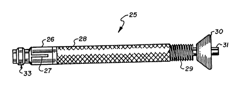
Figs. 2, 3, ~nd 4 show the prosthetic ligsment 25, shown to be prefersbly
formed from a brsided fabric and includes ss the femorsl sttschment end, the
expandable cone 26. The e~g- dr'le cone 26 is prefersbly attsched to the prosthetic
ligsmcnt 25 in the msnufscturine process. The opposite end of ligament 25 is shown
threaded therealong at 29 for receiving, as a tibisl attachment end, 8 flattened
cone 30. FJsttened cone 30 is holed and thresded longitudinslly therethrough to be
turned over the threaded prosthetic ligsment tibial end 29. The flsttened cone
outer circumference is shown to tsper outwardly from the edge of one face to the
edge of the other f-ce with the lesser diameter cone fsce to wedge in tunnel 11
open end. To provide for e~p~ ng cone 26, ss shown best in Fig. 4, the prosthetic
ligament 25 includes a bngitudinal passage thst is open therethrough and receives
n inner shaft 31 telescoped to slide therein. The inner shsft 31, ss illustrsted best
in Figs. SA and SB, includes a thresded end 32 thst is for turning }nto 8 thresded
centraJ opening in s flst face of an expansion snchor 33. The e~pansion anchor 33
is shown to hsve, opposite to the flst fsce, a cylindrical nose snd is flsred or
tapered outwsrdly back from the nose end into 8 cylindrical center section 34. Bsck
therefrom the anchor tapers inwsrdly from an end edge 35 into a ssddle 36 snd
then flares outwsrdly from 37 to terminate in a rear edge 38. The anchor resr edge
38 is aligned with the expanding cone 26 open end to trsvel therein. The cone 26
is tapered inwardly from a widest point at its open end, the opening therethrough
reducing in dismeter, as illustrated in broken lines at 26a in Figs. SA snd 5B to a
continuous groove 39 formed sround the cone inner circumference ~t spproximstely
the closed ends 278 of longitudinsl slots 27. As shown best in Fig. SB, pulling the
-12- l 336~58
~Yp~n~;on anchor 33 into the expandable cone 26 causes that cone end to expand
outwardly, flaring the cone at longitudinal slot ends 27a. With continued travel of
the expansion anchor therein the anchor rear edge 38 will engage and seat in groove
39 having flsred the cone 26, as shown in broken lines in Fig SB, locking the
05 expansion anchor therein. Shaft 31 travel to so move expansion anchor 33 into the
eYp~n~' hle cone 26 is shown by the arrow 8 in Fig. SB. So arranged, travel of
the anchor within the expandable cone 26 causes it to break at the slot 27 end 27a
flaring the cone end outwardly into a flattened cone. The ~oxp~qn~l~hle cone 26 is
thereby erected to have to its greatest diameter at its rearmost point the tunnel
11, that cone flared portion filling the tunnel end and permanently seating therein.
This coupling has been found in pull-out tests performed thereon to resist separation
at forces in excess of 1300 neutrons that is estimated to be a maximum force as
could reasonably be expected to be exerted on the ligament.
Fig. 6 shows another embodiment of a prosthetic ligament 40 that includes,
as a femoral attachment end, deep threads 41 that are formed in the ligament
femoral end. These threads are preferabJy formed during the fabrication thereof as
are smaller machine threads 42 that are formed in the ligament tibial attachmentend. Threads 41, as illustrated, are preferably cut deep and wide to bite deeplyinto the tunnel femoral anterior cortex end, which threads are cut or formed therein,
as set out hereinabove, as a last step in the tunnel formation process. As with the
description of prosthetic ligament 25, the machine threads 42 that are formed asthe tibial attachment end are to receive a flattened cone 43 turned thereover. In
the prosthetic ligament 25 and 40 embodiments the tibia attachment component is
preferably the flattened cone shaped collar that is longitudinally center threaded
therethrough for turning over the threaded prosthetic ligament thre0ded end suchthat the cone lesser diameter end will travel into the tibia tunnel 11 end. Flattened
cone 43 turning is preferably accomplished by fitting a tool, not shown, into a hole
or holes 43a that extend through the cone to the greater diameter face thereof,
and turning the collar with that tool. This arrangement provides for adjusting
3 0 ligament tension by appropriately turning the collar on the ligament to engage the
tibia tunnel end.
-13- 1 336058
As set out hereinabove, the tunnel 11 femoral end, sfter it has been
tapped or otherwise machined to form threads therein, sccommodates the threaded
end 41 of prosthetic ligament 40 turned therein. This tapping or threading can be
nc.~, Fliched by insertion of the canulated drill into the femur anterior lateral cortex
05 end of tunnel 11, as described hereinabove, followed by a tap turned therein. Such
tap is inserted along the prepared tunnel 11 and is turned to tap that femur anterior
cortex at 44, as illustrated in Fig. 7. Whereafter, the prosthetic ligament 40 of Fig.
6 is turned into the tunnel end 44, as illustrated in Fig. 7, to where the ligament
end butts sgainst the tunnel end, locking the ligament therein. Thereafter, prosthetic
ligament length and tension adjustment is accomplished, as set out above, by turning
the flattened cone 43 on the prosthetic ligament thread end 41, to where it engages
the tibia end of tunnel 11. Setting prosthetic ligament tension is preferably
accomplished while maintaining the patient's leg 10 in the attitude shown in Fig. 1.
Fig. 10 shows a threaded cylinder 50 that is a preferred configuration of
1 5 a femoral attachment for an allograft ligament 49 for securing a ligament end in
the femoral anterior cortex end of tunnel 11. Cylinder 50 is shown to have the
appearance of a set screw, in that it is threaded at 51 along its entire length, as
shown in Figs. 8 and 9, and includes a center hex-sided cavity 53. Additionally,the cylinder 50 preferably includes longitudinal holes sa that are radially formed
therethrough around the center hex-sided cavity 53. The cavity 53 is formed in aligament attaching end of cylinder 50 that is preferably dished below a circumferential
lip 54. The cylinder 50 is preferably fabricated of a biodegradable material such as
a polylactic acid plastic or like material, to be absorbed by the body in the healing
process. Fig. 10 shows an end of allogrHft ligament 49 being attached to cylinder 50
by passing a suture 56 at spaced intervals around the ligament end, which suture is
also selectively threaded through longitudinal passages 52 using a needle 57. The
ligament end is then drawn tightly against the cylinder 50 dished out portion, fitting
below the circumferential lip 54. Shown in Figs. 10 and lOA, for installation, the
allograft ligament is unrolled and is wrapped around a hex-sided driver 58, which
driver should be long enough to be turned from without the tunnel 11. The allograft
ligament has an overlapping layered appearance, as shown in the sectional view of
Fig. 10A. To install the hex-sided driver 58 the allograft ligament is unwrapped so
as to loosen it at the center wherethrough the hex-sided driver is fitted. The
1 336058
-14-
ligament and driver are then fitted into tunnel 11 and the cylinder 50 threads 51
are turned into a tapped femur end 60 of tunnel 11. After seating of the cylinder,
the hex-sided driver 58 is removed and the allograft ligament 49 stretched out, as
illustrated in Fig. 11. The cylinder threads 51, are preferably machine type threads,
05 as shown in Figs. 8 through 11, and therefore thread 51 depth is not as great as is
the depth of threads 41 of the prosthetic ligament 40 of Fig. 6. It should, however,
be understood that the threaded femoral attachment end of both the prosthetic
ligament 40 and cylinder 50 can have the same or different depth of thread within
the scope of this disclosure.
With cylinder 50 seated as described and the allograft ligament 49
stretched therefrom, to complete the ligament rcconstruction, the allograft ligament
49 is pulled tight so as to achieve a certain tensile loading thereon. The ligament
tibial end is then secured to the tibia as by bending the ligament 49 tibial endacross the bone surface from the tunnel 11 entry and is fixed thereat as by driving
staples into the bone that span the ligament. Of course, a tibial attachment device
such as a collar arrangement, that could be pinched around the ligament, not shown,
or the like, can be used for attaching the allograft ligament tibial end to the tibia
within the scope of this disclosure.
The above sets out the preferred end connector arrangements and system
2 0 for their use for ligament reconstructive surgery as particularly applicable to a
replacement of the anterior cruciate ligament with a prosthetic or allograft ligament.
It should, however, be understood that the described procedures is and/or the devices
described herein can be appropriately modified to be used to surgically replace the
posterior cruciate ligament and/or other knee ligaments, within the scope of this
disclosure. It should also be understood that any or all of the described ligament
end connectors can be fabricated from a material or materials such as a polylactic
acid plastic, or the like, to be absorbed by the body during the healing process.
Obviously, however, the described connectors can be manufactured from an appropriate
metal to remain in the bone after the healing process has taken place.
The present disclosure has, of course, been directed to both prosthetic
and allograft ligaments. Within present technology, a prosthetic ligament
msnufactured by Zimmer U.S.A. is believed to be suitable for the described application.
Approval for this ligament for use as an implant is currently being sought from the
- 15- 1 3 3 6 0 5 8
Food and Drug Administration for human implant. It should, however, be understood
that the present invention is not Jimited to use with such particulflr prosthetic
ligsment only snd that the end connection devices set out herein can be used with
other prosthetic ligaments ss may be now available or ss may be developed in the
05 future within the scope of this disclosure. Of course, allograft ligaments from
csdavers are presently available for human implant.
The above described configurations of sn allograft femoral device, shown
as cylinder 50 in Figs. 8 through 11, has been laboratory tested ss set out in Table
I hereinbelow. Table I shows the pull out strength of the femoral attachment
component, the cylinder 50 that incorporates three (3) sutures 56 each threaded
through snd back through psssages 52, securing the ligament end to the cylinder
end. Each suture was capable of sustaining a twenty (20) pound tensile load. The
test standsrd thereby being that the attachment device, cylinder 50 snd its suture
connection would sustain at least a pul~out tensile stress of sixty (60) pounds. The
test data in Table I shows that this criterior was met, the minimum sustained load
shown ss sixty seven (67) pounds. Additionally, it should be noted that all tests
were performed using bones thAt csme from specimens that were older than sixty
(60) years st the time of death. The advanced age of the bone specimens used, it
can be sssumed, incresses the chances that the bones will be softer snd more porous,
2 0 grestly reducing the bone strength. Tests performed on younger bones, it csn
reasonsbly be assumed, would likely show grester failure strengths. Even using the
aged spe~h -, the tests demonstrated the utility of the connector as the minimum
bsd sustained of siKty seven (67) pounds was still greater thsn the combined suture
strength of sixty (60) pounds, with the other tests for the different thread
configurations showing much greater failure strength.
-16- I 33605~
TABLE I
SPECIMEN SPECIFICATIONS
M ateriaJ Threads
Test Note Thread'M ajorM inor Per Load
Number Date Length DjA. Dia. Inch tLbs.)
7-ag-86 .702 .374 .236 9 267
2 7-29-86 .702 .374 .236 9 129
3 7-29-86 .702 .374 .236 9 165
4 8-07-86 1.134 .373 .236 9 169
8-07-86 .594 .374 .236 9 133
6 9-04-86 .750 .328 .236 12 115
7 9-04-86 .750 .328 .236 12 67
8 9-04-86 .750 .328 .236 12 85
9 9-04-86 .750 .328 .236 12 142
14 9-12-86 .750 .375 .280 18 120
9-12-86 .750 .375 .280 18 220
16 9-12-86 .750 .375 .280 18 520
17 9-12-86 .750 .375 .280 18 120
NOTE: MATERIAL TEST NOTE NUM13ER 10-13 INVOLVE TIBIAL
ATTACHMENT DEVICES AND DO NOT APPLY.
Herein has been set out a preferred surgical procedure or system and
ligament end attschment devices. It should, however, be understood that the present
disclosure is made by way of example only and that variations to the procedure or
system and the described ligament end connectors are possible without departing
05 from the subject matter coming within the scope of the following claims, which
claims we regard as our invention.