Note: Descriptions are shown in the official language in which they were submitted.
336205
IMPROVED PRODUCTION OF PRE-RECORDED TAPE CASSETTES
_
Thls Inventlon relates to a method and apparatus for
recordlng and loadlng magnetlc tape cassettes.
As used In thls speclfIcatlon the term "magnetlc tape
cassette" wlll be understood to relate to an assembly
comprlslng an encloslng caslng or shell houslng two
spools wound wlth a length of magnetlc tape. Such
cassettes are wldely known for use wlth audlo or vldeo
equlpment and also as a recordlng store of data for
computers. Regardless of Its Intended functlon the
magnetlc tape carrled on the spools Is of substantlally
the same form, comprlslng a flexlble supportlng substrate
on one face of whlch there Is formed an oxlde layer
exhlbltlng speclflc magnetlc propertles. Currently, the
most well known types of cassettes are the Phllllps*
"compact" cassette for audlo and data Informatlon and the
JVC "VHS" cassette for vldeo Informatlon.
Magnetlc tape for use In such cassettes Is manufactured
In rolls many thousands of metres long suffIclent to flll
very many cassettes. Thls tape Is wound Into the plastlc
houslngs or shells to form cassettes uslng a speclal
machlne known as a cassette loader. The Informatlon to
2~
be stored on the magnetlc tape may be recorded after the
tape has been loaded Into the cassettes ("ln-cassette
dupllcatlon") or may be recorded before loadlng Into the
cassettes ("reel-to-reel duplIcatlon"). If the tape Is
* Trade m~rX
-2- 1 3 3 6 2 0 5
recorded ~efore belng loaded Into cassettes thls Is
usually achleved by recordlng the same programme
repeatedly onto a length of tape suffIclent to flll
several cassettes, and then loadlng a length of the tape
contalnlng one programme Into each of several cassettes
sequentlally. In order to ensure that the length of tape
loaded Into a cassette contalns the whole of a programme
(and In thls context, the term "programme" wlll be
understood to mean a complete set of use slgnals, be they
vldeo or audlo slgnals for entertalnment or educatlon
1 0
purposes, or data slgnals for operat~ng a computer or
servlng as the worklng basls for computer operatlon) It
Is necessary to leave a certaln unrecorded length of tape
between the end of a recorded programme and the
commencement of the next adJacent recorded programme. It
has also been known to record Identlflable "cue tones"
at the beglnnlng or end (or both) of the programme
materlal so that the physlcal break In the tape can wlth
certalnty be made In such a way that It does not Implnge
on the recorded programme materlal. In thls way, the
loader can detect the correct polnt to complete one
cassette and start the next.
In audlo cassette productlon (and some data cassettes),
programme materlal can be recorded at hlgh speed In reel-
to-reel recordlng machlnes havlng large-dlameter reels of
use tape, speclal machines having been developed for thls
purpose. Typlcally, magnetlc use tape equlvalent to
about 30 to 40 C 60 cassettes Is recorded In thls way
_3_ 1 33620~
from a length of "master" tape on whlch the programme
_ Informatlon has been recorded wlth hlgh fIdelIty.
Thls arrangement Inevltably means that audio cassette
reel-to-reel recording equlpment is somewhat bulky, a
recordlng deck havlng a relat~vely large surface area in
order to accommodate the supply spool and take-up spool
~n side-by-slde relationshlp. In practlce, this is a
relatlvely mlnor dlsadvantage In a conventlonal audlo
context because of the hlgh speed at whlch recordlng Is
0
effected. Thls Is posslble wlth audlo slgnals because of
thel r comparatlvely narrow bandwldth. Recordlng can
thus be carr~ed out at a very hlgh speed wlthout loss of
record~ng quallty. For example, recordlng may be carr~ed
out at from 32 to 128 tlmes playback speed. Thls enables
16
hlghly productlve audlo cassette recordlng operatlons to
be set up wlth relatlvely few copler machlnes so that the
slze of the machlnes themselves Is at least tolerable.
In vldeo recordlng, however, the recorded slgnals are of
much hlgher bandwldth so that recordlng of such slgnals
cannot be carrled out at high speed wlthout serlous loss
of recordlng qualIty. Even a recordlng speed 50 per cent
hlgher than playback speed wlll normally result In an
unacceptable reductlon In qualIty and In most cases the
recording speed has to be equal to the retrieval or
playback speed. Because of thls relatlvely slow speed of
record~ng, many more copier machines are needed for video
copylng than for audlo recordlng; Indeed It Is not
_4_ 1 3 3 6 2 0 5
-
unknown for a slngle establIshment to have several
thousands of copiers operatlng at the same tIme. Vldeo
coplers havlng the same size as open reel audlo coplers
would requlre about 400 per cent more space than an In-
cassette copler and thls is totally unacceptable. The
same applles to hlgn bandwldth audlo copylng e.g. R-DAT
and S-DAT format. Although there are the above descrlbed
dlfferences between the treatment of audlo and vldeo tape
due to dlfferences In the nature of the slgnals there Is
In practIce no dlfference In the magnetlc tape Itself
0
except that tape for audlo slgnals Is wlder In order to
accommodate the incllned recordlng stripes recorded by
the rotatlng tape heads of a vldeo recorder or playback
machlne. For the above reasons, In-cassette copylng of
vldeo tapes remalned customary practlce for many years.
However, the method has always been regarded as
unsatisfactory for a number of reasons. Flrst, the
process Is labour Intenslve due to the requlrement to
change the cassette after each recordlng had been
completed. Secondly, the mechanlsms whlch handle the
slave cassettes In the players are Inherently complex and
sufflclently prone to unreliable performance that they
can give signlflcant practical problems after a prolonged
perlod of heavy use. Th~rdly, slnce the players have to
start and stop between recording each cassette, and slnce
each cassette contalns tape whlch may have come from
dlfferent reels of varylng quallty, It Is necessary to
sample each one after the recordlng has been completed In
order to ensure the recordlng process has proceeded
, -5-
1 ~620~
correctly.
Flndlng a solutlon to the problems of exlstlng vldeo
coplers has been the subJect of much actlvlty In the
Industry and machlnes whlch elImlnate many of the above-
enumerated problems are now avallable.
The Sony Sprlnter system, for example, passes a master
tape carrylng a "mlrror Image" of the magnetlc recordlng
patterns In contact wlth a slave tape through a recordlng
statlon at whlch the two tapes are pressed together wlth
a magnetlc fleld applled so that the mlrror Image
magnetlc pattern Is transferred reversely. The two tapes
are statlonary relatlve to each other and thus both may
be transported at hlgh speed through the recordlng
statlon. Thls speed faclllty reduces the space
requlrements for a partlcular productlon level relatlve
to the large space whlch would otherwlse be needed.
QualIty recordlng requlres a very strongly recorded
master tape whlch Is dlfflcult to produce, productlon
requlrlng sPeClallst expenslve recordlng technlques, and
the prlnt-through recorder Is also Itself expenslve tG
produce slnce vldeo coplers for commerclal cassette
productlon operat~ons represent a small mar~et, whose
supply Involves the economlc dlsadvantages of small scale
productlon operatlons. However, quallty of recordlng Is
obtalnable at hlgh speed and In a labour-savlng manner,
thus maklng the machlne commerclally deslrable and used
Increaslngly. The Tape Automatlon ETD system comprlses a
* Trade mark
1 336205
recordlng head for recordlng the programme material onto
use tape, and a palr of Independantly operatlve motors
(for example stepplng motors) for effectlng rlm drlve of
each of two non-cassette (open) spools whlch are In use
mounted to the apparatus for rotatlon about a common axis
~n parallel Juxtaposed planes of rotation, one such spool
servlng as a supply spool whlch In use dlscharges use
tape to the recordlng head and the other such spool
servlng as a take-up spool to take up recorded tape
Issulng from the recordlng head. The stepper motors are
operable subJect to control means for detectlng changes
In speed of tape supply and take-up whereby the relatlve
speed of drlven rotatlon of the spools can be adJusted to
equallse tape supply to and tape take-up from the
recordlng head. The space requlrements of the machlne
are no more than about 25 per cent more than for
conventlonal In-cassette mass coplers, an acceptable
Increase in practlce. The spools of tape used In thls
system are very large dlameter unbraced spools, that Is
the tape Is wound on a core wlthout the guldlng dlscs
conventlonally used on open reels. By wlndlng the tape
at the correct hlgh tension such open spools can be made
hard and effectively self-supportlng. They are known as
"pancake" spools for obvlous reasons.
Although the above machlnes largely deal wlth many of the
above-outlined pro~lems, wlthout loss of recordlng
qualIty, they do Impose very severe loglstlc and
organisatlonal problems In a manufacturlng operatlon. In
-7_ 1 33~6 2 0~
. ,
order to gain maximum beneflt when using the pancake
- spools it Is desirable to record the whole length of tape
on a spool before removing It for wlndlng. Thls Is
necessary In order to malntaln an adequately llght and
suffIclently constant wlndlng tenslon to keep the spool
in shape. Thls can Involve up to 48 hours between
pancai<e spool changes. However, other constralnts such
as the ratlo of playback machlnes (produclng the
recordlng slgnal from a master cassette) to vldeo loaders
and the average batch size requlred, mean that In order
0
to flll a whole pancake spool with recorded programme
materlal, It Is sometimes necessary to record dlfferent
programmes at dlfferent polnts along the length of tape
on the pancake spool. For example, the sltuatlon may be
as follows:-
Ratlo of playback machlnes to
recordlng machlnes 500:1
Average programme length 90 mlnutes
Average batch required 1000
Length of tape In each pancake spool 4000 m
Programmes/pancake spool 29 approx
It wlll be appreclated that all 500 recordlng machlnes
wlll record the same programme materlal so that to
produce a batch of 1000 will requlre a glven programme to
be played only twice by the master playback machlne and
recorded on two successlve lengths of each spool. Slnce
each pancake spool can record 29 programmes each will on
-8- 1 3 3 62 05
-
average contain 14 or 15 different programmes each
- recorded twlce. It will be appreclated that this
sltuation, after only a short perlod of cassette wlndlng,
results In a number and varlety of recorded cassettes
such that unacceptable levels of operator superv~sion and
Interventlon are called for If uncertalnty as to the
Identity of programme materlal recorded on the varlous
Indlvldual cassettes (whlch all appear vlsually Identlcal
from the outslde) Is to be avoided, and Indeed if wlnding
operatlons are to be conducted efflclently at all.
0
In the case of the Sony Sprlnter system, each of, for
example, ten pancake spools Is recorded from the same
programme materlal. However It Is stlll very easy to
lose track of the recordlng programme, whlch can lead to
problems of Identlflcatlon slmllar to those Just
descrlbed. These problems often result In the necesslty
to play bacic each of a large number of recorded cassettes
In order to establlsh what has been recorded on them.
The technlcal problem to whlch the present Inventlon
relates, therefore, Is that of unamblguously and
automatlcally Identlfylng the programme materlal recorded
on a length of tape to enable the programme content of a
cassette conta~ning such tape to be Identlfled wlthout
the need to play back the tape.
Accordlng to one aspect of the Inventlon, there Is
provlded a method of recordlng magnetlc tape for
-9- 1 3 3 6 2 0 5
subsequent loadlng into cassettes, In whlch between
- slgnals representlng the programme materlal recorded
along sectlons of the tape there are recorded slgnals
representing data related to and/or Identlfylng the
programme materlal and whlch, upon playbaci< of the tape
act to control a cassette loading mach~ne and/or
apparatus such as a label prlnter assoc~ated therew~th.
Convenlently, slgnals representlng the programme materlal
and the data are recorded onto the magnetlc tape by
transportlng the tape past a recordlng head or transducer
at a recordlng statlon and In any event the programme
materlal Is preferably recorded from a master recordlng
made on a recordlng medium (e.g. a master cassette) on
which only the programme materlal Is recorded (although,
In fact, some of the data may also be recorded on the
master). Alternatlvely, a master may flrst be sub-
mastered to provlde one or a pluralIty of sub-master
recordlngs each used to record part of a very large
number of programme coples onto magnetlc tape on open or
pancaice spools, each sub-master havlng data encoded
thereon to Identlfy It as dlstlnct from Its parent and
other sub-master(s).
Alternatlvely, the programme materlal may be recorded
onto magentlc tape by transportlng the sald magnetlc tape
and a tape carrylng a master recordlng of the programme
materlal through a recordlng statlon Includlng means for
presslng the two tapes into close contact In an applled
, o 1 3 3 6 2 0 5
-
magnetlc fleld to Induce magnetlc "prlnt-through" of the
- recorded slgnal from the master recordlng tape onto the
use tape.
In preferred embodlments of the Inventlon, the magnetlc
tape Is recorded wlth the programme materlal and data by
transportlng It through the recordlng statlon from an
open supply spool to an open take-up spool.
Accordlng to a second aspect of the Inventlon, there Is
0
provlded a method of produclng cassettes of magnetlc tape
recorded wlth programme materlal, comprlslng the steps of
preparIng a reel of tape having a pluralIty of lengths
recorded wlth programme materlal Intercalated wlth
recorded slgnals representlng data, transferrlng the reel
to a cassette loader havlng a transducer responslve to
the sald recorded data slgnals, transportlng tape Into a
cassette past the sald transducer, controlling the
operatlon of the tape transport In dependence on slgnals
generated by the sald transducer, and further controlllng
means for formlng vislble Indlcla representlng the
Identlty of the programme materlal recorded on the tape
for applIcatlon to the shell of the cassette.
The means for formlng the vlslble Indlcla may comprlse a
label prlnter and the method may then Include the step
of automatlcally applylng a label prlnted wlth Indlcla
correspondlng to the sald data slgnals onto the shell of
the cassette durlng wlndlng of the length of tape
, 1- 1 33~205
._
recorded wlth the programme materlal to whlch the data
- relates or Immedlately thereafter.
In one embodlment the sald means for formlng vlslble
Indlcla comprlse means for dlrectly marklng or engravlng
the shell of the cassette belng loaded durlng wlndlng of
the tape or Immedlately thereafter.
The data slgnals detected by the sald transducer may
Include data representlng the length of tape occupled by
0
programme materlal to whlch the data relates, and the
method Includes the step of storlng the data length
slgnal after detectlon thereof, generatlng slgnals
representlng the dlsplacement of tape durlng wlndlng
thereof, comparlng the sald dlsplacement-representatlve
slgnals wlth the sald stored slgnals and Inltlatlng
deceleratlon of the tape transport when there Is a
predetermlned dlfference therebetween. The present
Inventlon also comprehends magnetlc tape recorded along
successlve lengths thereof wlth flrst slgnals
representlng programme materlal and second slgnals
representlng data Indentlfylng the recorded programme
materlal and/or one or more characterlstlcs of the
recorded tape and/or Its productlon, the sald second
slgnals actlng to control the operatlon of a cassette
loader and/or assoclated apparatus upon detectlon thereof
by a transducer sensltlve to the magnetlc recordlng on
the tape.
-1 2- 1 3 3 6 2 û 5
._
Preferably the said fIrst slgnals are televlslon slgnals
- and the said second s~gnals are recorded on the tape ~n
pulse code form.
These pulse code slgnals are preferably recorded on the
tape as pulse wldth modulatlon of the slgnal recorded on
the sync track of the vldeo recordlng.
Accordlng to a further aspect, the present Inventlon
provldes apparatus for produclng recorded magnetlc tape
0
comprlses means for generatlng programme slgnals,
recording transducer means to which the sald programme
slgnals are fed, means for generatlng data slgnals to be
supplled to the sald recordlng transducer means, tape
transport means for transportlng the magnetlc tape to be
recorded past the sald recordlng transducer means, and
control means connected to the sald programme slgnal
generator and the sald data slgnal generator and
operatlve to control energlsatlon of the transducer means
such that data signals and related programme slgnals are
recorded in sequence along the tape.
The sald recordlng transducer means may comprlse a slmple
recordlng transducer or two separate transducers spaced
along the path of the magnetic tape, one for recording
slgnals representing programme materlal and one for
recordlng slgnals representlng data.
In a further aspect of the Inventlon there Is provlded
1 33b205
-13-
apparatus for produclng cassettes of recorded magnetlc
tape comprlslng apparatus as deflned above for produclng
successlve recordlngs of programme materlal and data onto
a length of magnetlc tape, means for wlndlng the tape
onto open spools after recordlng, a transducer sensltlve
to the recorded data slgnals and operatlve to generate
electrlcal control slgnals In response thereto, a
cassette loader havlng a drlve splndle engageable wlth a
spool of a cassette to be loaded, drIve means for the
splndle, a control clrcult operatlve to control the
splndle drlve means In accordance wlth electrlcal control
slgnals recelved from the sald sensor, and cassette
IdentlfIcatlon means operatlve to provlde vlslble Indlcla
representatlve of the programme Identlfled by the data
slgnal.
In the preferred embodlment of the Inventlon the sald
cassette Identlflcatlon means comprlses a label prlnter
operatlve to prlnt labels bearlng Indlcla determined by
the sald data slgnals, and there are further provlded
means for aPplylng the labels to cassette shells before
belng eJected from the cassette loader.
The label prlnter may operate to produce Indlcla In the
form of machlne readable bar codes on the labels to be
applled to the cassettes, In whlch case there are
preferably provlded means for readlng the bar code labels
and dlrectlng the cassettes to one of a pluralIty of
label applIcatlon statlons at whlch prelImlnarlly
-14- 1 3 3 ~ 2 0 ~
-
prepared labels from a stack thereof ~re applled to the
cassettes. Alternatively, the bar codes are read by means
which directs the cassettes to one of a plurality of pack-
ing stations or the bar codes are read and the cassettes
sorted and directed to storage. Of course, read could be
effected at a station and label selection effected thereat.
More generally, of course, the Inventlon can be
consldered as a system for encodlng serlal blnary data by
asynchronous modulatlon of a regularly occurrlng event
slgnal, In whlch the event slgnal Is Interrupted to
encode the blnary data and decodlng of the Interrupted
event slgnal to regenerate the blnary data Is effected by
determlnlng the length of successlve perlods In whlch the
event slgnal Is Interrupted and unlnterrupted
respectlvely.
The present Inventlon can thus be consldered to Include a
system for recordlng serlal blnary data onto a magnetlc
tape In the presence of a regular sl~nal recorded
thereon, In whlch the blnary data Is recorded as
asynchronous Interruptlons of the regular slgnal. In
thls latter case, then, the regular slgnal Is the
synchronlsatlon control signal recorded along the edge of
a vldeo tape and the Interruptlons are formed elther by
selectlve erasure of a prevlously recorded
synchronlsatlon control slgnal or by selectlve Inhlbltlon
of the recordlng transducer by whlch the synchronlsatlon
control slgnal Is recorded, and selectlve Inhlbltlon of
the recordlng transducer may be effected by short-
clrcultlng the recordlng transducer durlng the Intervals
for whlch the synchronlsatlon control slgnal Is to be
Interrupted.
1 336~0~
-14A-
Accordingly, in one aspect, the present invention
resides in a A method of producing a plurality of cassettes
of recorded magnetic tape by first recording a length of
magnetic tape transported in a first direction with
programme signal sections (P) representing programme
material and with data signals recorded after each of the
programme signal sections (P), and thereafter loading each
part of said length of tape containing a respective said
programme section into a respective said cassette,
characterized in that the recorded data signals have an
information content related to the immediately preceding
programme signal section (P) as considered during recording;
in that during loading of the tape into cassettes the tape
is transported in the opposite direction to said first
direction and the data signals relevant to each successive
programme signal section are read back from tape prior to
loading of the corresponding said tape part into a said
cassette; and in that the read-back data signals are used to
control cassette loading or other apparatus for carrying out
an operation in respect of said corresponding tape part, the
cassette loading or other apparatus being controlled in a
manner which depends on the programme signal section
recorded on the said corresponding tape part as represented
by the information content of the data signals.
. ~ ~ ~
- 14B - 1 33~205
In another aspect, the invention resides in a
magnetic tape recorded along successive lengths thereof with
a plurality of first signal sections (P) representing
programme material and second signals sections representing
data, each of the second signal sections being recorded
after a respective one of the first signal sections and
being in a form which can be read at tape transport speeds
higher than those at which they are recorded, characterized
in that each said second signal section represents data
including or comprising information signifying the identity
of the programme represented by, and/or representing the
length of tape occupied by, the said first signal section
(P) preceding said second signal section as considered
during recording, and in that each second signal section is
of a form such that during a subsequent cassette loading
operation in which each tape part containing a first signal
section is loaded into a respective cassette, the second
signal section can be read back from tape, prior to loading
into a cassette of the tape part containing the first signal
section to which said second signal section relates, and
used to control cassette loading or other apparatus for
carrying out an operation in respect of the corresponding
tape part.
.
, ~
- 14C - ~3362~5
In a further aspect, the present invention resides
in a method of preparing magnetic video tape for subsequent
loading into cassettes by recording a length of magnetic
tape with programme signals (P) and data signals related to
the programme signals (P), characterized in that the said
data signals are recorded as asynchronous modulation of the
regularly occurring video synchronization signals of the
video sync track (S) of the video tape whereby to generate
signals for controlling a cassette loading machine and/or
other apparatus for cassette production.
In another aspect, the present invention resides
in a Magnetic tape prepared for loading into a cassette by
having recorded along successive lengths thereof first
signals representing programme material and second signals
representing data related to the recorded programme signals
(P) and/or one or more characteristics of the recorded tape
and/or its production, characterized in that the said second
signals are recorded as asynchronous modulation of the
regularly occurring video synchronization signals (S) of the
video sync track.
1 336205
- One embodlment of the present Inventlon wlll now be more
partlcularly described, by way of example, wlth reference
to the accompanying drawlngs, In whlch:
Flgure 1 Is a dlagram schematlcally showlng apparatus for
the productlon of recorded magnetlc tape formed as an
embodIment of the Inventlon;
Flgure 2 Is another dlagram schematlcally Illustratlng a
1 0
machlne for produclng recorded cassettes of magnetlc tape
from open spools or pancake reels of tape produced by the
apparatus of Flgure 1;
Figure 3 Is a dlagram Illustratlng a length of magnetlc
tape recorded wlth vldeo programme materlal data;
Flgure 4 Is a dlagram representlng, on an enlarged scale,
a part of the magnetlc tape of Flgure 3 wlth a schematlc
indicatlon of the slgnals recorded thereon; and
Flgure 5 Is a schematlc representatlon of a typlcal vldeo
synchronlsatlon slgnal as recorded on or read from a
magnetlc vldeo tape.
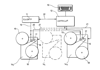
Referrlng now to Flgure 1, magnetlc tape Is recorded by a
programme dupllcatlon assembly comprlslng a master
playback machlne 11, a maln recordlng controller 12
havlng a keyboard 13 for Inputtlng Informatlon, and a
-16- 1 3 3 6 2 0 ~
bank of tape recorders for recordlng the vldeo output of
the master playback machlne 11 and the data output of the
maln recordlng controller 12. As can be seen In Flgure 1
the slave tape recorders, whlch are Identlfled with the
reference numeral 141 to 14n (where n, as mentloned
above, may typlcally be 500 or In some cases may be 1000
or more) are equlpped wlth drlve means for carryln~ large
open spools or pancake reels 15 from whlch tape Is drawn
over a capstan past two spaced recordlng heads 16,17
onto a further open spool or pancake reel 18. The master
0
playback machlne Is a conventlonal hlgh quallty vldeo
recorder, of the type generally avallable for domestlc or
professlonal use, modlfled so that vldeo slgnals from a
master programme cassette are output not to a VDU but to
a programme output llne 19 leadlng to the recordlng heads
16 of the recordlng machlne 141 In parallel. The
recordlng machlnes may have a constructlon and operatlon
as descrIbed and Illustrated In our co-pendlng CDN Patent
ApplIcatlon No 546,015. As mentloned above, the bank of
recorders 14 may comprlse several hundred such recorders
all recelvlng the same vldeo slgnals derlved from the
master playback machlne and the master cassette run
thereon. Typlcally, about 500 recorders may be present
In the bank. Each of the recordlng heads 17 Is connected
to a llne 20 on whlch are applled data slgnals from the
maln recordlng controller 12, whlch In thls embodlment
comprlses a sultably programmed Interface computer. The
computer also has a control output llne 21 for conveylng
slgnals for controlllng the productlon of "local~
-17- 1 3 3 6 2 0 5
-
informatlon derived dlrectly from the indlvldual
- recorders 14, such as a recorder identiflcation code,
wh~ch ~s thus recorded at approprlate po~nts along the
tape as controlled by the Interface computer: thls
latter is also connected dlrectly to the master playback
machlne 11 by a llne 22 for the purpose of detectlng the
beglnnlng and end of the programme materlal and for
monltorlng and/or controlllng a pause perlod whlle the
playback machlne 11 rewlnds for a subsequent run or whlle
the cassette Is replaced wlth another contalnlng the same
or a dlfferent programme.
The Interface computer 12 llnks the master playback
machlne 11 to the bank of recorders 14 and controls each
productlon run on the basls of a productlon plan Input to
the computer vla the keyboard 13 before the run Is
started (or afterwards and prlor to playback of the
master cassette to the end of the flrst master
programme). Once a productlon run is complete, the
computer prompts manual loadlng of the next master
cassette and recycles. The slngle control llne 20
transmlts global Informatlon output of the Interface
computer 12 to each recorder 14 In the recorder bank, the
second llne 21 belng used to transmlt trlgger slgnals as
dlscussed above.
Turnlng now to Flgure 2, the cassette loadlng statlon
comprlses at least one cassette loader generally
Indlcated 30, whlch In thls embodiment Is of the type
-18- 1 3 3 6 2 0 5
descrlbed and Illustrated In our co-pendlngEæO Patent
ApplIcatlon No 0 210 844A. The loader 30 Is one of a
plurallty of such loaders the number of whlch wlll
depend entlrely on the number of recorders 14 In the bank
of recorders, but due to the much faster speed of loadlng
as compared to recordlng, the number of loaders 30 wlll
be much less than the number of recorders 14 (typlcally
one loader wlll be capable of loadlng the collectlve
output of about 50 recorders). The loader 30 Is adapted
to recelve an open spool or pancake reel 18 taken from a
recorder 14 after havlng been recorded wlth a sequence of
programme materlal and data slgnals In alternatlon In a
pattern whlch wlll be more partlcularly descrlbed In
relatlon to Flgure 3. Thls wlll Include Informatlon for
Identlfylng the programme materlal recorded on the tape
wound Into the cassette and In practlce certaln other
Informatlon. The data also Includes an Index "markN or
"cue tones" slgnlfylng one end of one set of slgnals
representlng programme materlal and the data slgnals.
Before proceedlng to a detalled descrlptlon of the
loadlng statlon In Flgure 2, the format of the recordlng
on the tape wound on the open spool or pancake reel 18
wlll be dIscussed.
Flrst, It wlll be appreclated that because of the
relatlvely large number of recorders 14 all recelvlng
slgnals from the master playback machlne 11, It Is
posslble to produce a large number of coples of an
t 336205
-
orlginal master tape relatlvely quickly. For example, by
~ playlng the tape In the master playback machlne 11 only
twice there wlll have been produced 1000 coples of the
programme recorded thereon. Slnce the length of tape
wound on a pancake reel can take very much more than thls
(typlcally In the reglon of 30 programmes) and because It
Is IneffIclent to slow down and stop the pancake reels
once they have been set In motlon, and even more
ineffIclent to remove these from the recorder, place them
on a loader and load only a fractlon of the tape
1 0
contalned thereon before replacing It on a recorder and
recordlng further Informatlon, It Is normal practice to
record the whole length of a pancake reel wlth a number
of dlfferent programmes. For this reason It Is assumed
here that each pancake reel 18 after havlng been recorded
wlll contaln a plurality of dlfferent programmes, some of
them repeated several tImes along the length of the tape.
Because of sllght dlfferences between each of the
recorders 141 each pancake reel 18 so produced wlll have
mlnor dlfferences as concerns the preclse physlcal length
of tape used to record a glven programme. In order to
compensate thls It Is usual practlce to leave a
slgniflcant length of tape unrecorded In order to ensure
that no programme from a relatlvely slow recorder 14j Is
"cropped" durlng loadlng. It must be emPhaslzed here
that the dlfferences In speed between one recorder and
another are very small, typlcally less than 1 per cent,
but on the other hand It must also be appreclated that
the lengths of recordlng tape are extremely great,
-20- 1 3 3 6 2 0 ~
runn~ng into thousands of metres, and therefore even a
- very small percentage varlatlon can result In quite
slgnlflcant physlcal dlfferences In the posltlon of a
glven programme along the tape.
The present Inventlon, however, overcomes thls
dlsadvantage by means of the data control slgnals whlch
are recorded on the tape durlng recordlng. As can be
seen from Flgure 3 the tape of a recorded pancake has a
number of programmes recorded thereon In sequence. The
0
tape Includes a short termlnal length 1 used for
threadlng the tape of the unrecorded pancake on the
recorder. An Index mark 2 recorded on the tape as an
Interruptlon In the vldeo sync track after thls length
slgnlfles the start of the tape carrylng te flrst
recorded programme. The followlng length of tape P Is
recorded wlth the programme. Thls Is termlnated by a
length of tape 3 recorded serlally wlth pulse coded
Informatlon represented as a sequence of Interruptlons In
the sync tracic of the vldeo recordlng. A very short
length of tape 4 then separates the code slgnals from
another Index mark slgnlfylng the beglnnlng of the next
length of tape recorded wlth programme materlal. Thls
very short length Is determlned by the type of masterlng
system used In the recordlng procedure. If a slngle
shuttle master Is used, the very short tape length 4
represents the per I od durlng whlch the recorder Is paused
for the master cassette to rewlnd. If an alternatlng
master system Is employed, length 4 slgnlfles a perlod
-21- 1 3 3 6 2 0 5
-
Inserted Into procedures by the control system of the
recorder to ensure Inter-programme stabllity. The
sequence Index-programme-code-very short length ~s
repeated to the end of the tape (the programmes belng the
same or dlfferent and the codes recorded after each
programme representlng the detalls of the programme Just
recorded, then a flnal code block 6 at the end of the
tape Is followed ~y a short termlnal length 5
Inserted by the Interface computer to allow for handlIng
durlng wlndlng. The length 5 Is left at the leadlng
0
end of the flrst cassette to be loaded from the recorded
pancake reel 18.
The coded Informatlon In the code block 3 and generated
by the Interface computer 12 Is referred to as "global"
Informatlon. The code block 3 also Includes "local"
Informatlon whlch Is provlded by the encoder formlng part
of the recorder 14 on whlch the partlcular pancake reel
18 has been recorded.
The Index mark 2 and data 3 are recorded on the tape, as
mentloned earller, as pulses In the form of Interruptlons
In the sync track of the vldeo recordlng. The
Interruptlons are caused by control llne pulses of
var~ous length output from the Interface computer.
Durlng loadlng of the open or 'pancake' reels into
cassettes the tape Is transported at many tImes the
normal playback speed and It Is essentlal that the
slgnals whlch convey the coded Informatlon can be read
-22- 1 3 3 6 2 0 5
._
with accuracy and consistency: the form of these
- slgnals, as wlll be dlscussed below, ensures that thls
can be achieved.
First, as can be seen from Flgure 4, a magnetic video
tape T Is recorded wlth dlagonal "strlpes" D contalnlng
televlslon plcture slgnals comprlslng raster scan control
slgnals and plcture Informatlon: even In the so-called
"grey~ areas at the end of the programme recordlng the
tape has such Incllned strlpes D contalnlng the
televlslon raster scan control slgnals but no plcture
Informatlon. Llkewlse along one edge of the tape there
Is recorded a synchronlsatlon slgnal S the functlon of
whlch Is to provlde a reference slgnal for the operatlon
of a vldeo playback machlne to enable It to compensate
for mlnor varlatlons In the speed at whlch Its motors run
In relatlon to the speed at whlch the tape was
transported durlng recordlng. It Is thls sync track
whlch makes It posslble for a vldeo tape to be played
back succesfully on dlfferent playback machlnes.
The form of the vldeo sync track Is Illustrated In more
detall wlth reference to Flgure 5. The synchronlsatlon
slgnal Is recorded by successlvely applylng a magnetlslng
fleld across the vldeo tape for a very short tIme perlod
to cause saturatlon magnetlsatlon flrst In one dlrectlon
and then in the other. Figure 5 may thus be consldered
as the form of an electrlcal slgnal applled to a
recordlng transducer or one generated by a read
-23- 1 3 3 6 2 0 5
,. ~.
-
transducer, or alternatively as a representatlon of themagnetlsatlon state of the tape along Its length.
Successlve similarly dlrected peaks K1, K3 etc. are
spaced an equal dlstance apart and the tIme (when
regarded as an electrIcal slgnal) or dlstance (when
regarded as magnetlsatlon of the tape) between adJacent
peaks represents the tlme or dlstance between regularly
occurrlng events. The problem whlch Is addressed by the
present Inventlon Is that the data slgnals whlch are to
be recorded on the tape as selectlve Interruptlons of the
synchronlslng pulse slgnal K I occur In an entlrely
asynchronous manner and must therefore be equally valId
and detectable whenever In the synchronlsatlon pulse
cycle the data slgnals should commence, bearlng In mlnd
that because the tape Is belng transported at hlgh speed
It Is deslrable to keep the length of tape occupled by
the data code as short as posslble. Decodlng of the
coded data Is achleved by detectlng the sync track of the
tape as It Is transported at hlgh speed such as for
loadlng and segmentlng the encoded slgnal read from the
tape Into cells by reference to a stroboscoplcally
generated decode clocic slgnal whlch Is synchronlsed wlth
the tape movement so that Its frequency Is always
unlquely related to the pulse repetltlon frequency of the
sync track slgnal pulses Kl. Thls may be achleved
mechanlcally by means of a stroboscope wheel In the tape
transport mechanism or by electrlcal or electronlc means
as approprlate.
-24- 1 3 3 6 2 0 5
The sync track s~gnal pulses Kl may be consldered as
events whlch, dependlng on the encoded slgnal which
suppresses or erases certaln pulses, may or may not occur
In any glven cell In the sequentlal serles of cells Into
whlch the slgnal read from the sync track Is segmented
for the purpose of decodlng. Sequentlal cells of the
same sort (ie contalnlng events or not contalning events)
are then accumulated In the hardware decoder and
Interpreted as elther a blnary 1 or a blnary 0 dependlng
on the number of sequentlal slmllar cells counted. For
0
the purpose of decodlng the slgnals It Is necessary to
deflne an "Include perlod" as a perlod, measured In
elther tIme or dlstance (le as a slgnal or as a recordlng
on tape) for whlch the event Is allowed to take place to
form the code. Thus an Include 0 perlod Is a short
Include perlod, whlch upon decodlng glves rlse to a
blnary 0, whlIst an Include 1 Is a long Include perlod,
whlch upon decodlng glves rlse to a blnary 1.
Correspondlngly It Is necessary to deflne the concept of
an "exclude perlod" as a perlod, agaln measured In elther
tIme or dlstance, for whlch the event Is Inhlblted to
form the code. In thls case an "exclude 0" perlod Is a
short exclude perlod whlch, upon decodlng glves rlse to a
blnary 0, and an "exclude 1" perlod Is a long exclude
perlod whlch, upon decodlng glves rlse to a blnary 1.
As mentloned above a cell or "length cell" Is a perlod,
measured In elther tlme or dlstance, Into whlch the
-
-25- 1 3 3 6 2 0 5
encoded sl~nal Is se~mented for decodln~, and It Is
necessary to dlstln~ulsh between a ~full cell", namely a
length cell contalnlng an event, and sn ~empty cell~
whlch Is a length cell not contalnlng an event.
In the case of V~S-format vldeo tape, the control slgnal
recorded down the edge of the tape, whlch Is used as the
event, has a ~ifferent perio~ for PAL (Phase Alternative Line) fr~m that
for NISC (Nati~nal Televisi~n Syste~s Ccnnittee ~f Pm~rica), but
calc~lati~ns ~y b~ ~a~e for both syste~.
Dependlng on the tape productlon process one of two
methods may be employed to create the Include and exclude
perlods. The dlfferent effects of these two methods on
the control track must be taken Into account In the
calculatlons. The two methods are:-
a. By selectlve erasure of an exlstlng control track.
b. By selectlvely preventlng the recordlng of the
control track.
The actual method used depends on the type of tape
copylng system belng used and at what stage the code Is
belng Introduced.
As applled to the recordlng methods dlscussed In detall
In relatlon to Flgures 1 and 2, the control Pulses are
prevented from belng recorded by shortlng out the control
track record head to create the exclude perlods. Control
_ -26- 1 3 3 6 2 0 5
-
pulses are recorded by passlng a DC current through the
- control track head flrst In one dlrectlon and then In the
other. This creates short lengths of magnetic saturatlon
along the tape flrst In one sense and then the other as
descrlbed In relatlon to Flgure 5. The rapld change In
flux durlng replay creates the control pulse. Shortlng
out the head leaves the tape unrecorded and the
transitlon from saturated recordlng In elther sense to no
recordlng also creates a flux change In the replay head
and thus a pulse. These extra pulses may be seen as an
event by the decoder and must be taken Into account In
the calculatlons.
For calculatlon purposes upon decodlng It is necessary to
take ~nto account the followlng:
Worst Case (Length) - The mlnlmum Include or exclude
pulse length measured In tIme or dlstance requlred to
produce a set number of full or empty length cells (EC or
FC)-
Worst Case (Cell count) - The maxlmum number of full or
empty cells created by the Worst case (Length).
Best Case (Length) - The mlnlmum Include or exclude pulse
length measured In tIme or dlstance whlch could produce a
set number of full or empty cells. Thls must be
calculated for Include 1 and exclude 1 In order to
establish an upper llmlt for Include 0 and exclude 0.
1 3362a5
- Clearly the event per~od must be shorter than the Length
cell to guarantee that, when examlnlng an Include perlod,
an event wlll be seen. Also both Include and exclude 0
and Include and exclude 1 must be longer than the Length
cell in order that a full or empty cell may be created.
In order to mlnlmlse the tlme or dlstance used by the
code, a 0 may be considered as a mlnlmum of 1 length cell
(elther full or empty). Slnce all the posslble blnary
1 0
blt generators (Include 0, Include 1, exclude 0, exclude
1) are asynchronous to both the events and the length
cells, more than one full or empty cell may be decoded
having encoded a 0. Therefore, a 1 Is defIned as the
mlnimum number of sequential full or emPty cells
suffIclent to dlstlngulsh them from a 0.
In the exclude pulse worst case (ETD) an extra event Is
created at the beglnnlng and end of the exclude pulse.
Therefore the longest exclude pulse requlred to create
empty cells occurs If the exclude pulse starts
Immedlately after the beglnnlng of a length cell. Thls
flrst length cell must be decoded slnce full and
sufflclent tIme (dlstance) must be allowed for the
exclude pulse to envelope thls full cell plus the number
of empty cells required. However, the mlnlmum exclude
pulse must be sufficient to envelope length cells at the
maximum end of their tolerance band.
-28- 1 336205
-
Thls can be expressed more succ~nctly if:
E(mln) = minlmum exclude pulse perlod requlred
EC = number of empty cells requlred
LC(max) = longest posslble length cell perlod
Then
E(mln) = (EC+1)~LC(max)
0
The event perlod Is not relevant In exclude perlods. In
thls worst case an extra full cell Is added to the prlor
full cell count created by the prevlous Include pulse.
The cell count worst case wlll occur In an encodlng
system whlch does not produce extra events at the
beglnnlng and end of an excluslon pulse. In thls case It
is posslble for the excluslon pulse to occur up to one
event perlod after the beglnnlng of a length cell and the
cell stlll be empty. Thls means the end of the excluslon
pulse occurs at up to one event perlod after the end of
the (EC+1) length cell. If the end of the excluslon
pulse occurs Just after an event, then a further event
perlod must take place before a full cell Is reglstered.
Therefore, If a length cell Is less than twlce the length
of the event perlod, a further empty cell may occur
maklng a maxlmum of (EC+2) empty cells.
on the other hand the best case occurs when the length
-29-
- 1 336205
celi starts Immedlately after an event and the exclude
- pulse starts Just before the next event coupled wlth the
end of the exclude pulse occurlng Just after an event and
the length cell endlng Just before the next event.
Now, glven that the shortest exclude pulse wlll occur
wlth the mlnImum event perlod and If
E(mln) = mlnlmum exclude pulse perlod whlch could glve
rIse to the speclfled number of empty cells
0
EC = speclfied number of empty cells
EV(mln) = mlnlmum event period
LC(mln) = mlnlmum length cell perlod
Then:
E(min) = (EC*LC(mln)) - (2*EV(max))
The decoder has an event counter whlch Is reset every
length cell. Although thls reset pulse Is short, If It
Is colncldent wlth an event the result wlll be
Indetermlnate. Therefore In the ~'worst case"
calculatlons at least two events must be speclfled.
Thls worst case wlll occur when the Include pulse starts
Immedlately after an event, resultlng In an event perlod
passlng ~efore the flrst full cell can be created and
when the length cell ends Immedlately after an event wlth
the Include pulse endlng Just after the next event.
-30-
1 336205
~ The length wlll be greatest when the event perlod as well
as the length cell is greatest.
Thus If:
1(mln) = mlnlmum Include pulse perlod to ensure requlred
number of full cells
FC = requlred number of full cells
LC(max) = maxlmum length of cell perlod
EV(max) = maxImum event perlod
We can wrlte:
1(min) = ((FC-1)*LC(max)) + (2*EV(max))
The cell count worst case occurs when the Include pulse
starts Immedlately before an event and is followed
~mmed~ately by a length cell. The event included makes
the prev~ous cell full. From the worst case (Length), ~t
can be seen that the include pulse may extend two event
perlods beyond the end of the penultImate length cell.
Th~s could g~ve rIse to a further full cell, that Is a
total of (FC+2).
The best case on the other hand occurs when the Include
pulse starts Just before an event wlth the correspondlng
length cell having started Just after the prevlous event,
coupled with the penultImate length cell ending just
- _ 1 336205
before an event wlth the Include pulse ending Just after
the same event. Here, the shortest Include pulse wlll
occur wlth the mlnlmum event perlod.
Thus If:
1(mln) = mlnlmum Include pulse perlod whlch could glve
rIse to speclfied number of full cells
FC = speclfled number of full cells
LC(mln) = mlnimum length cell perlod
0
EV(mln) = mlnlmum event period
Then:
1(mln) = (Int((FC-1)*LC(mln))/(EV(mln)))*EV(mln)
When the encoded data Is belng recorded a short pulse
(typlcally In the reglon of 1 sec) represents blnary 0
during serial encodlng of global Informatlon and a long
pulse (typically In the reglon of 2 secs) represents
blnary 1 durlng serlal encodlng of global Informatlon,
whlIst a very long pulse (typlcally In the reglon of 4
secs) represents an Index mark.
Computer-generated short and long pulses are used to make
up global Informatlon, and also Local Informatlon Clocks
(LIC) to whlch the Indiv~dual recorders respond by
encodlng, wlth similar pulses, the requlred local
Informatlon to i~e recorded onto the tape. Each LIC
_ -32- 1 3 3 5 2 0 5
-
trlggers the recorder to encode one blt of local
Informatlon and record It onto the tape,and contalns
tlmlng Informatlon whlch controls the perlod of recorder-
generated long and short pulses maklng up the local
Informatlon codes.
Global Informatlon Is output dlrectly from the Interface
computer 11 along the control llne 20. The second
control llne 21 Is held Inactlve durlng global output
on llne 20.
The global Informatlon encoded as descrlbed above
typlcally has the followlng composltlon.
Catalogue number (for programme IdentlfIcatlon)
Catalogue number range - lO alphanumeric characters
Character range - From Ascll 32 to Ascll 95
Codlng method:-
The character range Is thus 63. The coded value Is
calculated by deductlng 32 from the Ascll value. The
resultlng number can be represented by a 6 blt word.
Thus, the complete catalogue number Is coded Into elght 6
blt words l.e. 48 blts.
Programme length
-33- l 3 3 6 2 0 5
Length unlts - Metres
- Length range - 0-511 Metres
Coding method:-
The programme length Is converted dlrectly Into a 9 bltblnary number.
DATE
0
The date Is coded In three parts:-
1. Day of month
2. Month in year
3. Year
1. Range of days: 0-31
Codlng method:-
The day number Is converted dlrectly Into a 5 bit binary
number.
2. Range of months: 1-12
Codlng method:-
The month number Is converted dlrectly Into a 4 blt
binary number.
3. Range of years: 1986-2017
Codlng method:-
An equlvalent year number Is calculated by subtractlng
1986 from the actual year. The range Is thus reduced to
-34- 1 336205
._
0-31. This Is converted dlrectly to a 5 blt number.
-
Tlme
The tIme Is coded In two parts:-
1. Hours 2. Mlnutes
1. Range of hours: 0-23
Coding method:-
The hour number Is converted directly Into a 5 blt blnary
1 0
number.
2. Range of minutes: 0-59
Coding method:-
The mlnutes number Is converted dlrectly Into a 6 bltblnary number.
The global Informatlon code sequence is thus as follows:-
Blt Count
Catalogue number 48
Programme length 9
Day 5
Month 4
Year 5
Hour 5
Minute 6
Note 1* 6
1 3362~5
Total 88
*Note 1 = Reserved for special use
Local Informatlon Is encoded onto the tape by therecorder In response to LIC (Local Informatlon Clock)
pulses from the Interface computer 11. Each LIC pulse Is
the slmultaneous transmlsslon of a long pulse on the maln
control llne 20 used for global output (slgnlfylng blnary
1) and a short pulse on the second control llne 21 from
the Interface computer 11 (slgnlfylng blnary 0). The
leadlng edges of the pulses must be colncldent to a
tolerance of +5 ms.
Local Informatlon has the followlng composltlon:-
ETD Number (Identlfylng the recorder)
Range of numbers: 0-102
Codlng method:-
Dlrect converslon of EVD number to a 10 blt blnarynumber.
Programme Number
Range of numbers 0-511
Codlng method:-
-36- l ~ 3 6 2 0 5
-
._
Dlrect Converslon to a 9 blt blnary number.
-
The local Informatlon code sequence Is thus as follows:-
Blt Count
EVD number 10
Programme number9
Note 1* 8
Total 27
Note 1* Reserved for speclal use. The followlng tabulated
sequence represents an entire code blocic as recorded on
the tape. The loadlng machine wlll of course read the
sequence In reverse.
BIT Functlon
1Catalogue Number
(MSB 1st Character)
48Catalogue number
(LSB Last Character)
49Programme length
(MSB)
67Programme length
1 336205
.
(LSB)
58 Day Number
(MSB)
62 Day Number
(MSB)
63 Month Number
(MSB)
0
66 Month Number
(LSB)
67 Year Number
(MSB)
71 Year Number
(LSB)
72 Hours Number
(MSB)
76 Hours Number
(LSB)
77 Minutes Number
(MSB)
_ -38- 1 3 3 6 2 ~ ~
-
82 Minutes Number
(LSB)
83 Reserved
88 Reserved
89 EVD Number
(MSB)
0
98 EVD Number
(LSB)
99 Programme Number
(MSB)
107 Programme Number
(LSB)
108 Reserved
ReferrIng back now to Figure 2 the tape loader 30 Is
Illustrated only In very schematic form for the purpose
of the present description. A maln support panel 31
carrles a sp~ndle 32 drlven by a drlve motor 33 (shown In
broken outline In Figure 2). Energlsation of the motor
33 causes rotation of the splndle 32 and thus of the
pancake reel 18 carried thereon to d~scharge recorded
magnetlc tape 7 through a path deflned by a series of
_39_ 1 3 3 6 2 0 5
_
-
rollers generally indlcated 34, Includlng a capstan 35 to
the splndle of whlch ~s fIxed an optIcal encoder (not
Illustrated) In the form of a dlsc havlng an annular
array of apertures wlth a llght source on one slde and a
photo detector on the other for encodlng the dlsplacement
of the tape as It Is loaded Into a cassette.
Empty cassette shells are stored on a rack 36 from where
they are transported Into a loadlng statlon 37 at whlch
the tape 7 Is Introduced and loaded, and from the loadlng
statlon 37 the, now fllled, cassette Is dlsplaced to a
dlscharge statlon 38. The manner In whlch the leader
tape In the cassette shell Is extracted, cut, spllced to
the leadlng end of the magnetlc tape 7, wound Into the
cassette shell, and the magnetlc tape 7 cut and spllced
to the free end of the leader tape, Is descrlbed In our
above-mentloned pendlng patent applIcatlon and these
mechanIcal operatlons form no part of the present
Inventlon whlch Is dlrected to the manner In whlch these
Indlvldual operatlons are controlled.
The tape gulde rollers 34 gulde the tape 7 past a
magnetlc reed head or transducer 39 whlch Is connected by
a llne 40 to a decoder 41 havlng output llnes 42 and 43,
the flrst of whlch leads to a central control panel 44
and the second of whlch leads to a bar code label prlnter
45.
The central control panel 44 has an output llne 46
_ ~40- 1 3 3 6 2 0 ~
leading to the motor 33 drlving the splndle 32 carrylng
the pancake reel 18, and an output llne 47 leadlng to the
motor 48 drlvlng the capstan 35 whlch controls the
dlsplacement of the tape Into the loadlng station 37 and
Is connected, as mentloned above, to the optlcal encoder
for produclng feedback slgnals representlng the actual
dlsplacement of the tape.
The data slgnals recorded on the tape 7 thus control the
operatlon of the machlne loadlng the tape Into the
1 0
cassette shells and also the prIntIng of bar code labels
Identlfylng the programme content and productlon hlstory
of the cassette Itself. In operatlon, after the tape 7
has been threaded past the rollers 34 and the leadlng end
placed on a spllce block 50 at the loadlng statlon 37,
the control unlt 44 Is operated, vla a keyboard, to
Indlcate to the system that a new pancake reel 18 has
been placed In posltlon and the capstan motor 48 and maln
reel drlve motor 33 are placed on standby whllst the
loader performs the flrst tape splIclng operatlon,
wlthdrawlng a leader tape from the fIrst cassette shell,
cuttlng It, spllclng one cut end to the leadlng end of
the magnetlc tape 7 and then passlng a slgnal to the
control unlt 44 to Indlcate that the flrst spllce has
25 been successfully completed. The motors 48 and 33 are
then energlsed, together wlth a further motor, not
Illustrated, whlch drlves a splndle on whlch the hub of
the spool withln the cassette shell at the loadlng
statlon ~s engaged so that magnetlc tape 7 ~s unwound
-41- 1 3 3 6 2 0 5
from the pancake reel 18 and wound onto the cassette at
- the loadlng statlon 37 after havlng passed the rollers
34. As the flrst code block 6 on the magnetlc tape 7
passes the transducer 39 thls reads the slgnals
represented thereby and passes them along the llne 40 to
the decoder 41 which decodes the relevant sect~ons and
passes slgnals along the llne 42 to the control unlt 44
Indlcatlng the length of the programme recorded on the
tape belng wound Into the cassette. The controller 44
compares thls Informatlon wlth data comlng from the
encoder linked to the capstan 35 and, a predetermlned
tlme (or rather a predetermlned distance) before the end
of the programme starts to decelerate both the maln reel
drlve motor 33 and the capstan 35 ready for the arrlval
of the flrst Index mark 4 whlch wlll slgnlfy the end of
16
the programme and, upon arrIval, wlll cause the control
unlt 44 to stop the motors and Inltlate a tape spllclng
operation for cuttlng the tape at a polnt between the
Index mark 4 and the next code block 6 along the tape.
When the flrst code block 6 Is read and the slgnals
passed to the decoder 41 thls also decodes the relevant
Informatlon concernlng the programme materlal and
productlon hlstory and slgnals representlng these are
passed along the llne 43 to the label prlnter 45 whlch Is
thus energlsed to prlnt a bar code label representlng the
data read from the tape. The label, after prlntlng, Is
automatlcally passed to a label appllcator 51 posltloned
closely adJacent the loadlng statlon 37, and Is trlggered
-42- 1 3 3 6 2 0 5
._
to apply the label to the cassette shell elther durIng
~ loadlng of the tape 7 bearlng the programme ~dentlfled by
the label Just prlnted, or ~mmedlately after loadlng has
been completed as the fllled cassette Is transferred from
the loadlng statlon 37 to the dlscharge rack 38. Once
the label has been successfully applled a slgnal Is
transmltted to the control unlt 44 along a llne (not
illustrated) and the tape cassette loadlng cycle can
recommence wlth the next length of tape 7.
Slnce the short length of blank tape between each Index
mark 4 and code block 6 Is very short the transducer 39
wlll, In pract~ce, read the subsequent code block 6
Immedlately after the Index mark 4 and the data
represented thereby wlll be decoded by the decoder 41 and
stored In the short term buffer memory of the control
unlt 44 so that the necessary Informatlon for control of
the next tape loadlng operatlon Is already present
Immedlately the conflrmatlon slgnals from the tape
spllclng unlt 50 and the labelled applIcator 51 are
recelved to allow the motors 33 and 48 to be re-energlsed
to commence the next loadlng cycle.
Loaded cassettes bearlng the bar code label Identlfying
the tape recordlng on the magnetlc tape contalned In the
cassette shell are then removed from the dlscharge rack
38 and fed to a sort llne where the bar code labels can
be automatIcally read and the cassettes d~rected to label
appllcator statlons at which prlnted labels Identlfylng
-43-
1 33620~
-
the programme and containing, for example, advertislng
~ and other normal label material can be applled.
The apparatus of the present Inventlon also allows
recordlngs to be made on a speculatlve basls slnce the
data concerning the programme materlal recorded on a
pancake reel 18 Is carrled on the tape Itself and It Is
poss~ble to keep the recorders operatlng fulItlme
recordlng those programmes whlch It Is antlclpated wlll
be In demand. The pancake reels 18 can i~e stored wlthout
0
belng put Into cassettes and wlthdrawn from store and
loaded Into cassettes when demand requlres. If the
demand for any partlcular programme materlal does not
arlse It Is a slmple matter magnetlcally to wlpe the
recordlng from the tape 7 and rerecord a new programme,
somethlng whlch Is not convenlent once the tape has been
loaded Into a cassette slnce thls would requlre
Indlvldual cassette recorders and, almost Inevltably,
elther expensive automatlc cassette recorder loadlng
equlpment or even more expenslve labour.
Because of the nature of the data slgnals as
Interruptlons In the vldeo sync track the data recorded
on each cassette cannot be copled by a conventlonal vldeo
cassette recorder and the presence of code blocks on a
tape wlll therefore serve as a verlfIcatlon check on the
authentlclty of the programme recordlng.
It wlll be appreclated that data recorded on tape may be
1 336205
recorded as ordered magnetlc domalns or as randomlsed
~ magnetlc domalns (eg an interruptlon In a control signal)
and the expresslon "recorded" as used hereln should be
construed accordlngly. The data wlll In general be
provlded by the Interfaced computer llnked to slgnal
recordlng means but could merely be data recorded after
completlng the programme materlal recordlng of a pancake,
for example, data encoded on the tape by wlndlng machlne
and representlng any one or more of the Identlty of the
wlndlng machlne, the date of wlndlng, cassette or
0
cassette batch Identlty and/or any one or more Items of
other Informatlon.