Note: Descriptions are shown in the official language in which they were submitted.
~ 33638~
ONE-HANDED PERCUTANEOUS TRANSLUMINAL
ANGIOPLASTY STEERING DEVICE AND METHOD
Field of the Invention
The present invention relates to steering or
torquing devices for manipulating or guiding a guide wire
or catheter for percutaneous transluminal angioplasty and
related medical procedures.
Background of the Invention
Percutaneous transluminal angioplasty has recently
become well known in the art as a delicate and artful
procedure which has revolutionized medical treatment of
atherosclerotic stenosis in arteries. The use of a
catheter to dilate an atherosclerotic stenosis in blood
vessels was first disclosed in 1964 by Dotter and
Judkins. These investigators reported the development of
a series of coaxial tapered dilating catheters that could
be placed percutaneously through femoral artery
atherosclerotic obstructions. The technique was
subsequently modified by Gruntzig, who developed the
balloon catheter concept. Today, balloon angioplasty is
widely used to treat arterial stenosis or arterial
blockages in lieu of more invasive procedures such as
coronary artery bypass grafting, vascular surgery and the
like.
Coronary angioplasty is now a very well known
procedure. The utility of the present invention will be
described in relation to coronary angioplasty although it
has applications as a steering device for angioplasty of
any vessel, as well as for other medical procedures
involving steering a distal end of an elongated wire or
strand by manipulating a proximal portion of the strand.
In the initial stages of a coronary angioplasty, a
guiding catheter is inserted into the femoral artery in
the groin. The guiding catheter is subsequently passed
through the femoral artery into the aorta and over the
~/~ ~
-2- 1 3 3 6 3 8 4
aortic arch, and then maneuvered into the ostium of the
coronary artery under fluoroscopic guidance. In order to
dilate a coronary artery stenosis, a balloon catheter is
directed through the guiding catheter and into the
coronary artery until the deflated balloon is positioned
across the stenosis. The balloon is then briefly
inflated, thereby expanding the stenosis and relieving
the blood vessel of the obstruction.
- In order to guide the balloon catheter to the
location of the stenosis, the balloon catheter is
equipped with a guide wire which extends well beyond the
distal end of the balloon catheter. The initial step in
inserting the balloon catheter into the coronary artery
involves advancing the guide wire beyond the guiding
catheter and into the coronary artery under fluoroscopic
guidance. After the guide wire is in place in the
coronary artery, it is used to guide the balloon catheter
into position by sliding the balloon catheter along the
guide wire. In order to direct the guide wire
successfully into position within the coronary artery
without causing injury to the lining thereof, precise
control of the guide wire is re~uired. To provide such
precise control, steering devices have been developed
which allow precise rotational control of a J-tip which
is generally provided at the distal end of the guide
wire. Because the guide wire has extremely limited
rotational flexibility, rotation of the steering device
will generally result in a corresponding rotation of the
J-tip. Because the guide wire must have considerable
linear flexibility in spite of the need for limited
rotational flexibility, workers in the field note that
one may retain good control of the forward movement of
the guide wire during insertion into the coronary artery
by limiting the distance between the location of the
steering device on the guide wire and the hub at the
proximal end of the balloon catheter. If the distance
-3-
1 336384
between the steering device and the hub of the balloon
catheter is relatively large, the control afforded the
operator will be diminished because of the increased
tendency for the guide wire to bend in a position between
the steering device and the hub of the balloon catheter.
Therefore, it is important that the distance between the
steering device and the hub of the balloon catheter
always be minimized. Preferably, this distance will be
limited to 2-3 centimeters. Therefore, when the guide
wire is being inserted into the coronary artery, the
steering device must be repositioned on the guide wire as
the guide wire is inserted further and further into the
artery. Because this is a very delicate and artful
procedure, it is very important for the operator to have
as much control of the guide wire as possible,
Furthermore, as the operator advances the guide wire, he
or she must simultaneously watch a fluoroscopic monitor.
Most operators have also found that they must hold the
hub of the balloon catheter with one hand as they grasp
the steering device with the other hand in order to
direct the guide wire. Although the prior art steering
devices which are presently available to workers in the
field provide for adequate rotational control of the
guide wire, it is tedious and distracting to advance the
guide wire using these devices because it is necessary to
use two hands to reposition them on the guide wire, and
the operator's attention is necessarily diverted away
from the monitor at a time when the operator needs to be
particularly attentive.
The prior art steering devices generally used in the
field of angioplasty today comprise a two-piece
disposable plastic device having a collet-type gripping
mechanism wherein a cap is screwed down over a plurality
of flanges which are thereby tightened down upon the
guide wire providing a tight grip thereof.
Unfortunately, in order to loosen the grip of the
1 336384
--4--
steering device, the operator must use two hands. One
hand is required to grasp the main body portion of the
steering device, while the other hand unscrews the cap
portion to loosen the collet-type mechanism. When the
steering device is repositioned on the guide wire, both
hands are again required to tighten the screw cap so that
the manipulation of the guide wire may be continued. It
will be appreciated that using both hands to loosen and
then tighten the steering device on the guide wire every
time the guide wire is advanced 2-3 centimeters can
become a very tedious and cumbersome requirement.
The present invention addresses these and other
problems associated with the use of a steering device for
percutaneous transluminal angioplasty and related medical
procedures requiring control of a guide wire or other
elongated strand-like tools. The present invention also
offers other advantages over the prior art and solves
other problems associated therewith.
Summary of the Invention
Accordingly, it is an object of an aspect of the ~L`~Shl~
invention to provide an improved guide wire steering
device for percutaneous transluminal angioplasty and
other related medical procedures which enables operators
to fully control the repositioning of the steering device
at various positions along a guide wire using one hand.
It will be appreciated that because one hand is generally
required to grasp the hub of the balloon catheter during
manipulation of the guide wire, it would be extremely
advantageous to control the gripping mechanism of the
steering device with a single hand. Thus, that one would
not be required to remove one's hand from the hub of the
balloon catheter in order to engage a portion of the
steering device so that the device may be repositioned or
so that the device may be manipulated to grip the guide
wire firmly. Furthermore, one's gaze would not be
~t~
:.
~5~ 1 3 3 6 3 8 4
distracted from the video monitor while repositioning the
steering device.
In one embodiment of the present invention, a
percutaneous transluminal angioplasty (PTA) steéring
device for directing passage of a remote portion of a
length of wire is provided. The device comprises
releasable gripping means for releasably gripping a
proximate portion of the length of wire. The gripping
means includes opposing gripping faces which cooperate to
grip the proximate portion of the length of wire
therebetween when the faces are manipulated so that they
are in a gripping position. The gripping means further
include manipulation means for manipulating the faces
into the gripping position. The manipulation means
include releasable locking means for locking the gripping
faces in the gripping position when opposing portions of
said locking means are engaged. The gripping faces
occupy a non-gripping position when the opposing portions
of said locking means are disengaged. Preferably, said
manipulation means includes means for engaging and
disengaging said releasable locking means. Said gripping
means preferably include opposing gripping members, each
opposing gripping member including one of said opposing
gripping faces. Preferably, the device further comprises
lateral engaging means for engaging the length of wire by
slipping the device laterally onto the length of wire.
In another embodiment, the PTA steering device of
the present invention comprises opposing gripping
members. Each gripping member includes a body member and
a gripping flange. Each of the gripping flanges have
gripping faces which cooperate to releasably grip a
proximate portion of a length of wire when the opposing
gripping members are manipulated so that the opposing
gripping faces are in a gripping position. The gripping
members include releasable locking means for locking said
opposing gripping faces in the gripping position when
6 1 336384
opposing portions of said locking means are engaged.
The opposing gripping faces occupy a non-gripping
position when the opposing portions of said locking
means are disengaged. When the opposing portions of
said locking means are disengaged, the length of wire
slides freely within said steering device, and when the
opposing faces are in the gripping position and said
locking means are engaged, the length of wire is
substantially bound in an engaged position with respect
to the device.
Other aspects of this invention are as follows:
A steering device for directing passage of a remote
portion of a length of wire, said steering device
comprising releasable gripping means for releasably
gripping a proximate portion of the length of wire when
said gripping means is manipulated by the exertion of a
force upon a gripping member of said gripping means so
that the gripping member is moved into a gripping
position, said steering device including releasable
locking means for locking said gripping member in a
gripping position in opposition to an opposing gripping
face of said gripping means, said locking means
including first and second engaging portions
interconnected with gripping member and said opposing
gripping face, respectively, such that when said
respective engaging portions are engaged with one
another, and the gripping member is in the gripping
position, the gripping member is retained in the
gripping position by said engaged engaging portions.
A steering device for directing passage of a remote
portion of a length of wire, said steering device
comprising releasable gripping means for releasably
gripping a proximate portion of the length of wire, said
gripping means including a gripping member and an
opposing gripping face which cooperate to grip the
proximate portion of the length of wire when said
gripping means is manipulated by the exertion of a force
1 336384
6a
so that said gripping member is in a gripping position,
said steering device including integral releasable
locking means for locking said gripping member in the
gripping position, said locking means including a latch
member interconnected with said gripping member and an
engaging portion interconnected with said opposing
gripping face, said gripping member being retained in a
gripping position when said latch member is engaged with
said engaging portion.
A steering device for directing passage of a remote
portion of a length of wire, said steering device
comprising releasable gripping means for releasably
gripping a proximate portion of the length of wire, said
gripping means including opposing gripping surfaces
which cooperate to grip the proximate portion of the
length of wire when said gripping means is manipulated
so that said opposing gripping surfaces are in a
gripping position, said steering device further
including releasable locking means for locking said
gripping surfaces in said gripping position, said
locking means being interconnected with said gripping
means, wherein said steering device has a single housing
structure such that said steering device can be readily
manipulated with one hand.
A percutaneous transluminal angioplasty (PTA)
steering device for directing passage of a remote
portion of a length of wire, said steering device
comprising releasable gripping means for releasably
gripping a proximate portion of the length of wire, said
gripping means including opposing gripping faces which
cooperate to grip the proximate portion of the length of
wire when said gripping faces are manipulated so that
they are in a gripping position, said steering device
including integral manipulation means interconnected
with said gripping means for manipulating said faces
into said gripping position, said steering device
further including integral releasable locking means
e~
1 336384
6b
interconnected with said gripping means for locking said
gripping faces said gripping position, wherein said
steering device has a single housing structure such that
said steering device can be readily manipulated with one
hand.
A method for releasably engaging a length of wire
comprising the steps of:
(a) slidably positioning a steering device having a
single housing structure onto the length of wire by
insertion of the wire into a bore of the housing
structure; and
(b) simultaneously gripping the length of wire with
said steering device and locking the steering device in a
gripping state by manually applying a first force to an
external surface of the steering device, whereby internal
gripping faces of the steering device engage the length
of wire.
A percutaneous transluminal angioplasty (PTA)
steering device for directing passage of a remote portion
of a length of wire, the device comprising opposing
gripping members, each gripping member having a main body
portion and a gripping flange, each of said gripping
flanges having gripping faces, the gripping faces of
opposing gripping members cooperating to releasably grip
a proximate portion of the length of wire when said
opposing gripping members are manipulated so that said
opposing gripping faces are in a gripping position, said
gripping members including releasable locking means for
locking said opposing gripping faces in said gripping
position when opposing portions of said locking means are
engaged, said opposing gripping faces being in a
non-gripping position when said opposing portions of said
locking means are disengaged, the length of wire sliding
freely within said steering
. ,~i
,
1 336384
6c
device when said opposing portions of said locking means
are disengaged and the length of wire being substantially
bound in an engaged position with respect to said device
when said opposing faces are in said gripping position
and said locking means are engaged.
A method for releasably engaging a length of wire
comprising the steps of:
(a) slidably positioning a steering device
including releasable gripping means for releasably
gripping a approximate portion of the length of wire onto
the length of wire by insertion of the wire into the
device, said gripping means including opposing gripping
surfaces which cooperate to grip the proximate portion of
the length of wire therebetween when said gripping means
is manipulated by the exertion of a translational force
upon said gripping means so that gripping surfaces are
moved into a gripping position; and
(b) simultaneously gripping the length of wire with
said steering device and locking the steering device in a
gripping state by applying a translational force to said
gripping means, whereby gripping surfaces engage the
length of wire.
Further features provide additional advantages.
These and various other advantages and features of
novelty which characterize the invention are pointed out
with particularity in the claims annexed hereto and
forming a part hereof. However, for a better
understanding of the invention, its advantages, and the
objects obtained by its use, reference should be made to
the drawings which form a further part hereof, and to the
accompanying descriptive matter, in which there are
illustrated and described preferred embodiments of the
invention.
1 336384
6d
Brief Description of the Drawings
In the drawings, in which like reference numerals
and letters indicate corresponding parts throughout the
several views,
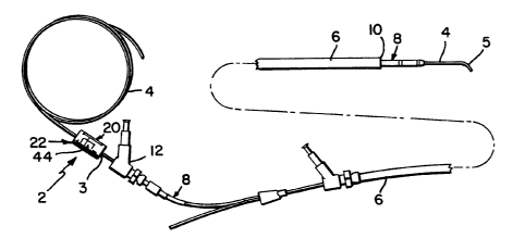
Fig. 1 is a schematic view of a steering device of
the present invention in connection to equipment
commonly used in percutaneous transluminal angioplasty;
Fig. 2 is a schematic sectional view of a coronary
artery with a portion of a guiding catheter and a guide
wire and other equipment commonly used in angioplasty,
and shown in Fig. 1, inserted therein;
Fig. 3 is a side elevational view of the steering
device of Fig. l;
Fig. 4 is an end view of the steering device shown
in Fig. 3;
. ~ .. r,
~7~ l 3 3 6 3 8 4
.
Fig. 5 is an enlarged cross-sectional view of the
steering device as seen from line 5-5 of Fig. 4 showing
the device in a non-gripping position;
Fig. 6 is an enlarged cross-sectional view similar
to that in Fig. 5 showing the device in a gripping
position;
Fig. 7 is a transverse cross-sectional view of the
device as seen from the line 7-7 of Fig. 3 showing a
locking mechanism in a locked position;
Fig. 8 is a transverse cross-sectional view of the
device as seen from the line 8-8 of Fig. 3;
Fig. 9 is a side elevational view of another
embodiment of the steering device of the present
invention;
Fig. 10 is an end view of the steering device shown
in Fig. 9 as seen from left to right;
Fig. 11 is an enlarged cross-sectional view of the
steering device as seen from line 11-11 of Fig. 10
showing gripping members in a non-gripping position;
Fig. 12 is an enlarged cross-sectional view similar
to the view shown in Fig. 11, but showing the gripping
members in a gripping position;
Figs. 13 and 14 are transverse cross-sectional views
as seen from lines 13-13 and 14-14 of Figs. 11 and 12,
respectively;
Figs. 15 and 16 are transverse cross-sectional views
as seen from lines 15-15 and 16-16 of Figs. 11 and 12,
respectively; and
Figs. 17 and 18 are transverse cross-sectional views
as seen from lines 17-17 and 18-18 of Figs. 11 and 12,
respectively.
Detailed Description of the Preferred Embodiments
Referring now to the drawings, and specifically to
Figures 1 and 2, the steering device 2 of the present
invention is used to manipulate or direct a guide wire 4'
1 336384
used in various medical procedures, preferably
percutaneous transluminal coronary angioplasty. The
steering device 2 grips the guide wire 4 so that the
guide wire 4 may be advanced or withdrawn within a
guiding catheter 6 which provides a passage for the guide
wire 4 and a balloon catheter 8 which may be advanced
along the guide wire 4, through the guiding catheter 6
and into the coronary artery 16. A rounded rubberized
tip 10 of the guiding catheter 6 is engaged in the ostium
14 of the coronary artery 16 to be sure that the passage
provided by the guiding catheter 6 directs the guide wire
4 and, therefore, the balloon catheter 8 into the
coronary artery 16 where the balloon catheter 8 may be
used to dilate regions of the coronary artery which may
be partially obstructed. The steering device 2 is very
critical in providing the operator with sufficient
control of the guide wire 4 and its tip 5 which is in the
shape of a "J~. It is believed that the present steering
device 2 will provide great advantages over the prior art
because it can be manipulated with one hand and does not
require a second hand to reposition the device 2 along
the guide wire 4. When the guide wire 4 is engaged in a
bore 3 (shown in Figs. 4-7) of the steering device 2 and
the steering device 2 grips the guide wire 4, the J-tip 5
can be rotated, as shown by the arrow in Figure 2, by
rotating the steering device 2 along an axis which runs
through the center of the bore 3 which is occupied by a
proximal portion of the guide wire 4. The J-tip 5 is
located at the distal end of the guide wire 4. It is
made of extremely flexible material which will bend
easily along its axis in a lateral direction, but will
not readily twist or provide a high degree of torsional
flexibility. The guide wire 4, and its J-tip 5 are
designed to allow for lateral flexibility, especially in
the J-tip portion 5, while substantially limiting
torsional flexibility. In this way, the J-tip 5 of the
1 336384
guide wire 4 may be easily manipulated by rotating the
steering device 2 when it is engaged with the guide wire
4 proximate to the J-tip which is inserted into the
arterial passageways of the body. With the help of a
fluoroscope, the guide wire 4 may be manipulated or
directed so that it will extend into areas within the
coronary artery 16 which may be partially blocked by a
stenosis 18 as is shown in Figure 2.
Although the present steering device 2 may be used
for a wide variety of medical operations involving
directing an elongated strand such as the guide wire 4 or
other medical tools such as fiber optic cables and the
like, it is most preferably used for percutaneous
transluminal angioplasty (PTA), especially coronary
angioplasty, which is generally carried out in the
following manner. The first step is to position the
rubberized tip 10 of the guiding catheter 6 in the ostium
14 of the coronary artery. The guiding catheter 6 is a
relatively large catheter having a diameter of about 3
millimeters such that the rubberized tip 10 will fit
within the ostium 14, but slide no further into the
coronary artery 16. The guiding catheter 6 is inserted
into the femoral artery near the groin of a patient
undergoing angioplasty and is passed from there under
fluoroscopic guidance into the aorta, up over the aortic
arch, and then maneuvered into the ostium 14 of the
coronary artery 16. Once the rubberized tip 10 of the
guiding catheter 6 is in place in the ostium 14, its
location is confirmed by injecting a small amount of
radio-opaque dye so that the dye may be observed
fluoroscopically as it passes into the coronary artery
16.
It will be appreciated that fluoroscopic guidance is
X-ray guidance. This method of monitoring internal
operations within the body employs a low energy radiation
which allows workers to see the movement of radio-opaque
1 336384
--10--
objects on a video monitor. A radio-opaque dye can be
used to visualize the passageway in the coronary artery
16 and to identify a blockage or stenosis 18 in the
artery.
It is very important that the guiding catheter 6 is
positioned carefully in the ostium 14 of the coronary
artery 16 under fluoroscopic guidance. Once it is there,
the shape of the guiding catheter 6 is such that it tends
to stay in place within the ostium 14 unless it is
specifically withdrawn or advanced to another area.
The next step is to insert a guide wire 4 having a
very small diameter, preferably about 0.016 to 0.018
inches in diameter, into a passageway created by the
guide catheter 6. The guide wire 4 is typically provided
with a small J-tip 5 at its distal end. The J-tip 5 is
generally made of a very delicate and flexible material,
whereas the remainder of the wire 4, although also quite
flexible, has virtually no torsional flexibility such
that when the guide wire 4 is rotated about its
longitudinal axis by an engaged steering device 2 at one
position, there is a substantially one-to-one torsional
response at the distal end. Once the wire 4 is pushed
beyond the tip 10 of the guide catheter 6, it is very
easy to monitor by watching the fluoroscope. It is then
cautiously maneuvered down the coronary artery 16 past
any obstruction or stenosis 18 which may exist therein.
Once the wire 4 is in place beyond the obstruction, the
very slender balloon catheter 8, which generally has a
deflated cross-sectional diameter of about 1.5 mm, is
slipped over the wire and through the guiding catheter 6
until it advances coaxially over the wire and into the
coronary artery. The balloon catheter 8 has a first
lumen which provides a passageway for the guide wire 4,
and a second lumen, separate from the first lumen, which
connects a compression device to a balloon incorporated
in the leading end of the catheter 8 (elements of 8 not
1 336384
shown). The center of the balloon is generally marked by
radio-opaque material which can be easily observed on the
fluoroscope so that the position of the balloon may be
determined. In this way, the balloon may be centered
over a lesion in the artery which is to be dilated, and
the compression device can then be used to dilate the
balloon to accomplish this task.
The balloon catheter 8 is advanced over the guide
wire 4 very cautiously. As the balloon catheter 8 is
advanced, the guide wire 4 also advances so that each
time the balloon catheter 8 is advanced, the guide wire 4
must be withdrawn in a corresponding increment so that
the guide wire 4 does not extend too far into the
coronary artery 16. This requires that the steering
device 2 be manipulated to release the guide wire 4 so
that the steering device 2 can be repositioned on the
guide wire 4 after the guide wire has been withdrawn an
increment corresponding to the increment which the
balloon catheter 8 has been advanced. Because the
operator is holding a hub 12 of the balloon catheter 8
when the steering device 2 is manipulated, it is
extremely advantageous to be able to alternately release
and grip the guide wire 4 with the steering device 2 by
manipulating the steering device 2 with one hand.
Once the distal end of the balloon catheter 8 is in
the desired position, the balloon is inflated with the
compression device for a period of typically about 30-60
seconds, during which time the flow of blood through that
particular portion of the artery 16 is totally blocked
and the plaque in the artery is compressed. The balloon
is then deflated and withdrawn back into the guiding
catheter 6 leaving the guide wire 4 in the coronary
artery 16.
When the prior art steering devices are used, it
generally takes two people to properly position the
balloon catheter 8 in the coronary artery 16. One person
-12- l 3 3 6 3 8 4
watches the monitor and pulls back on the guide wire 4,
and the other person gently pushes the balloon catheter 8
forward. Although the inventive steering device 2 may be
used during this operation, it is especially useful for
advancing the guide wire 4 into the coronary artery 16
which is an extremely delicate operation and requires
great care to avoid injuring the internal lining of the
coronary artery 16 with the tip 5 of the guide wire 4.
If one wants to maneuver the guide wire 4 past a
stenosis, and then through another branch of the artery,
one needs to have very good control and a minimum of
distraction. If the steering device is locked onto the
guide wire 4 in a position which is 6 or 7 cm. back from
the hub 12 of the balloon catheter 8 one will have
torqueability, but it will be difficult to exert the
forward pushing motion on the wire 4 when holding the
steering device 2 without flexing the wire in a position
between the steering device 2 and the hub 12. It is for
this reasons that the steering device 2 must grip the
guide wire 4 in a position which is only 2 or 3, or
preferably 1 or 2 cm. in back of the hub 12 so that there
will be minimal lateral deflection of the guide wire 4'
in positions between the steering device 2 and the hub
12. Therefore, advancing the guide wire 4 into the
coronary artery requires a great deal of finesse. It
must be advanced very gently. The worker must watch the
fluoroscopic monitor to see where the wire 4 is going and
hold the steering device 2 in one hand and the hub 12 in
the other. It will be appreciated that it would be very
distracting and time consuming to look down at the
steering device and remove the one hand from the hub 12
in order to use that hand to loosen a screw cap on the
forward end of a prior art steering device such as are
presently used in the art. In such a situation, the
prior art steering device would need to be loosened with
two hands, and then moved back 2 or 3, preferably 1 or 2
-13-
~ 336384
cm., tightened down again in order to grip the guide wire
4 in a different position. One would then repeat the
process of grasping the hub 12, reestablishing visual
contact with the monitor, and advancing the guide wire 4
by gently pushing the prior art steering device toward
the hub 12 before repeating the repositioning of the
prior art steering device again.
If one is not cautious enough when advancing the
guide wire 4, the J-tip 5 at the distal end of the guide
wire 4 can find its way under the plaque on the inner
surface of the artery even if the tip 5 is pushed
gently. The plaque can be lifted and may inadvertently
cause a serious dissection of the artery which has the
potential for severe complications. A great deal of
finesse is required as the operator delicately probes his
or her way throu~h the narrowing in the arteries.
Similarly, when one comes to a branch point in the
arteries as the wire is extended further into the vessel,
one does not want to make abrupt or gross movements. In
addition to pushing under plaque on the inner surface of
the vessels, the wire 4 may lift up the thin, delicate
inner membrane lining of the vessel called the intima. It
is possible that this membrane may be injured and may
flop into the lumen of the vessel and obstruct flow.
The present steering device 2 is preferably a
disposable device which will preferably be sterilized
prior to sale and delivery to an end user. It is
designed to move freely up and down an angioplasty guide
wire 4 without encountering substantial resistance when
it is in a non-gripping position, and it may be locked
into a gripping position by using translational force
exerted by a single hand.
Referring now to Figs. 3-8, one embodiment of the
steering device 2 of the present invention employs a
single gripping member 20 which forces the wire 4 against
gripping face 30b of an interior surface 21 of the main
-14- l 3 3 6 3 8 4
body 22 of the steering device 2 proximate the bore 3
when the gripping member 20 is in a gripping position as
shown in Figs. 6-8.
First and second body members 22a and 22b are joined
together to form the main body 22. The body members 22a
and 22b may be made of any suitable polymeric material
that would be selected by one skilled in the art for the
present purpose. The two body members 22a and 22b are
joined together by suitable means known to those skilled
in the art for joining such material together such that
the device 2 comprises an integral article of
manufacture. The gripping member 20 is preferably made
of a somewhat more flexible polymeric material than the
material used to make the body member 22. This material
may also be selected from materials which one skilled in
the art would find to be suitable for this purpose. The
gripping member 20 is preferably integrally molded of a
suitable polymeric material and includes a body portion
24 and flange portions 26. The ends of each of the
flange portions 26 distal to the body portion 24 are
bifurcated into two wedge members 28, each having
gripping faces 3Oa which form a part of a gripping
mechanism 31 which also includes gripping faces 30b on an
internal surface 21 of the main body 22 substantially in
the geometric center of a transverse cross section of the
steering device 2. The gripping member 20 is supported
by a leaf spring 32 which pushes the gripping member 20
away from the guide wire 4, which runs through the bore 3
in the center of the steering device 2. When the
gripping member 20 is in a non-gripping position as shown
in Fig. 5, the gripping member 20 and the gripping faces
3Oa are disengaged from the wire 4. When the gripping
member 20 is depressed toward the center of the steering
device 2, the gripping faces 30a of the gripping member
20 engage the guide wire 4 and press it against the
internal surface 21 of the main body 22, especially in
-1S- ~ 336384
the vicinity of the gripping faces 30b of the main body
22, so that the gripping faces 30a and 30b grip the wire
4 and hold it in place. The gripping faces 3Ob of the
main body 22 correspond to, and are located directly
opposite to and directly opposed to, the gripping faces
30a of the gripping member 20. The gripping mechanism
31, therefore, includes all of the gripping faces 30a and
30b and also includes recesses 34 in the main body 22 and
the walls of the main body 22 which define the recess 34
which force the wedge members 28 against the guide wire 4
when the gripping member 20 is depressed toward the
center of the steering device 2. The gripping mechanism
also includes the gripping member 20 and the internal
surface 21 of the main body 22. When the gripping member
20 is depressed sufficiently, and the gripping faces 3Oa
and 30b grip the guide wire 4, an upper surface 36 of the
gripping member 20 will be flush with the rounded outer
surface 38 of the steering device 2. Furthermore, the
gripping member 20 will depress the leaf spring 32 and a
locking mechanism 39 including two latching members 40
will become engaged within the steering device 2 so as to
lock the gripping member 20 in a gripping position as
shown in Fig. 6-8. When the gripping member 20 is in the
gripping position, the locking mechanism 39 is in a
locked position. It will be appreciated, however, that
the gripping mechanism 31 can be partially actuated to
provide some frictional gripping force without actuating
the locking mechanism 39, and thereby locking the device
2 in the locked position.
Referring now specifically to Fig. 7, when the
gripping member 20 is in the gripping position and the
locking mechanism is in the locked position, the latching
members 40 are engaged in latch recesses 42 in the main
body 22. In order to release the gripping member 20 so
that it will be forced away from the center of the
steering device 2 by the leaf spring 32 and disengaged
-16- 1 336384
from the wire 4, there are release levers 44 on each side
of the steering device 2. The release levers 44 form an
integral portion of the main body 22. Because the main
body 22 is made of a somewhat flexible material, the
integral connection between the release levers 44 and the
main body 22 acts as a nliving hinge~ which permit the
release levers 44 to be depressed. When they are
depressed simultaneously, by exerting translational
forces toward the center of the device 2 from both sides,
the flexible latching members 40 are forced toward the
center of the steering device 2 so that the latching
members 40 are pushed out of the latch recesses 42 and
the gripping member 20 is released and pushed upward away
from the center of the steering device 2, by the
resilient leaf spring 32. Therefore, it is possible to
depress the gripping member 20 when it is in the non-
gripping position shown in Fig. 5, so that it will occupy
the gripping position shown in Fig. 6-8, where the
locking mechanism 39 is shown in a locked position. In
order to release the gripping member 20 from the gripping
position shown in Fig. 6-8, the release levers 44 on both
sides of the steering device are depressed toward the
center of the device 2 to push the latching members 40
away from their corresponding latch recesses 42 so that
the locking mechanism 39 will disengage, thereby freeing
the gripping member 20 to become disengaged from the
guide wire 4 under the biasing force of the leaf spring
32. It will be appreciated that these operations can be
accomplished when the steering device 2 is grasped by a
single hand and that none of these operations would
require the assistance of another hand during maneuvering
of the guide wire 4 in the various operations required
during an angioplasty procedure.
Referring now to Figs. 9-18, which show a second
embodiment 2' of the present invention which includes two
opposing gripping members 20a and 20b. The main body 22'
~ 336384
of the steering device 2' includes two body members 22a'
and 22b' which are joined together in a manner similar to
that described for the steering device 2 shown in Fig. 3.
Two end caps 46 are rotatably connected to the respective
extremities of the main body 22. The end caps 46 may be
rotated 90 in order to provide for the alignment of
radial channels 50 and 52 in the end caps 46 and the main
body 22', respectively. When the respective radial
~ channels 50 and 52 are aligned, as is shown in Figs. 14,
16 and 18, a length of the guide wire 4' may be inserted
transversely into the steering device 2'. In order to
prevent the guide wire 4' from coming out of the steering
device 2' the end caps 46 can be rotated 90 so that the
radial channels 50 and 52 are no longer in alignment.
The rotation of the end caps 46 is permitted by indexing
recesses 54 in the main body 22' which permits indexing
pins 56, which are integral parts of each of the end caps
46, to slide within the respective indexing recesses 54
as the respective end caps 46 are rotated axially with
respect to a transverse cross-section of the main body
22'.
When the guide wire 4 is inserted in the steering
device 2' as shown in Fig. 11, the gripping members 20a
and 2Ob can be depressed toward the center of the
steering device 2' so that the gripping members 20a and
20b engage and grip the guide wire 4. When the opposing
gripping members 2Oa and 2Ob are depressed, the
respective opposing flange portions 26a and 26b, and
particularly the wedge members 28a and 28b, which form
the bifurcated end portions of the respective flange
portions 26a and 26b, are forced downward and outward
toward the respective axial extremities of the steering
device 2' and as the respective wedge members 28a and 28b
are forced up again bosses 58 in each respective end cap
46 which define conical recesses 60 in the respective end
caps 46. When the respective opposing gripping members
-18-
1 3363~4
2Oa and 2Ob are depressed, upper and lower latching
members 40a and 40b on each side of the steering device
2' engage so that a locking mechanism 39'is in a locked
position. When the locking mechanism 39' is in a locked
position, the upper and lower gripping members 20a and
20b are in a gripping position wherein gripping faces 30a
of the upper gripping member 20a and 30c of the lower
gripping member 2Ob are engaged with and grip the guide
wire 4'. In order to disengage the upper and lower
latching members 40a and 40b respectively, which are
located on each side of the steering device 2' and,
therefore, latch the respective gripping members 20a and
20b on both sides of the guide wire 4', release levers
44' are squeezed to force the lower latching members 40b
on each side inward toward bore 3' in the center of the
steering device 2'. When the lower latching members 40b
are forced inward, they are individually disengaged from
the upper latching members 40a, thereby releasing the
opposing gripping members 20a and 20b which are then
forced away from each other and away from the center of
the steering device 2' by the biasing affect of the
resilient flange portions 26a and 26b of the respective
gripping members 2Oa and 2Ob, which are made of a
resilient, flexible polymeric material as previously
described with respect to the gripping member 20 of the
device 2 shown in Figure 3.
The steering device 2' shown in Figures 9-18 is an
integral unit and is preferably made of suitable
polymeric materials that would be selected by one of
skill in the art for such a device. Preferably, these
materials include resilient, flexible, polymeric
materials which are biocompatible with the intended use.
This device 2' is preferably disposable and is preferably
sterilized prior to distribution to its end user.
The gripping mechanism 31' of the device 2' includes
the opposing gripping members 20a and 20b and their
-19- 1 3 3 6 3 8 4
various parts including the opposing gripping faces 30a
and 30c. Also included in the gripping mechanism 31' are
the bosses 58 in each respective end cap 46 which define
the conical recesses 60 in the respective end caps. The
bosses 58 wedge the wedge members 28a and 28b against the
guide wire 4' when the respective gripping members 20a
and 20b are depressed toward the center of the device 2'.
It will be appreciated that the respective gripping
mechanisms 31 and 31' and the respective locking
mechanisms 39 and 39' which include their respective
release levers 44 and 44', may all be actuated using
direct translational force exerted by a single hand
grasping the respective steering devices 2 and 2'. The
translational movement of the respective elements of the
respective devices 2 and 2', which results from the
translational force applied to these elements is
sufficient to actuate respective changes in the various
positions occupied by the respective devices 2 and 2'.
Translational force, as used herein, means a linear force
as opposed to a rotational force.
The present invention enables one of skill in the
art to releasably engage a length of wire so as to direct
passage of a remote portion of the length of wire during
percutaneous transluminal angioplasty and related medical
procedures.
As used herein, wire means any elongated strand-like
member, such as a PTA guide wire, a fiber optic bundle or
strand, a catheter, or the like.
It is to be understood, however, that even though
numerous characteristics and advantages of the present
invention have been set forth in the foregoing
description, together with details of the structure and
function of the invention, the disclosure is illustrative
only, and changes may be made in detail, especially in
matters of shape, size, composition, and arrangement of
-20- 1 336384
parts within the principles of the invention to the full
extent indicated by the broad general meaning of the
terms in which the appended claims are expressed.