Note: Descriptions are shown in the official language in which they were submitted.
1 3~5~9
1 This invention relates to refractory composite
2 articles and to methods of producing such articles. More
3 particularly, the invention relates to refractory composite
4 articles which are hard, tough, dimensionally stable, resistant
to corrosion and erosion and capable of operating satisfactorily
6 through extended ranges of temperatures. The invention also
7 relates to methods of producing such articles.
9 In recent years, a large and growing need has emerged
for articles exhibiting a number of characteristics which are
11 individually hard to achieve but which collectively have made
12 attainment seem almost impossible. For example, the articles
13 have been desired to be hard, tough and wear-resistant. The
14 articles have also been desired to be resistant to corrosion and
to erosion and to acids and bases normally encountered in
16 commercial and industrial environments. The articles have also
17 been desired to provide these characteristics through ranges of
18 temperatures of several thousands of degrees centrigrade.
19
A considerable effort has been made, and substantial
21 sums of money have been expended, to provide articles which meet
22 the above specifications. In spite of such efforts and such
23 expenditures of money, problems have still remained. A material
24 has still not been provided which meets all of the parameters
25 specified above.
26
27 In U.S. Patent No 4,397,901issued to me on August 9,
2~ 1983, for "Composite Article and Method of Making Same" and
29 assigned of record to the assignee of record of this
application, I disclose and claim a refractory composite
31
32
r ~
~ ' ' ~
. _,, .~
.'-
~ ~ 33~9
1 material which fulfills the parameters specified above. For
2 example, the article disclosed and claimed in u.S~ Patent No.
3 4,397,901 is hard, tough, dimensionally stable, resistant to
4 corrosion and erosion and capable of operating satisfactorily
through extended ranges of temperatures in excess of 2000~.
6 The article disciosed and claimed in Patent No. U.S.4,397,901 ls
7 also relatively light and is able to provide the characteristics
8 discussed above even when produced in relatively thin layers.
This invention provides a matrix and a substrate in a
11 combination which meets all of the conditions specified above
12 but which has enhanced characteristics relative to the material
13 of U.S. Patent No.4,397,901. In this invention, the substrate and
14 the matrix have a minimal bond and have different coefficients
of thermal expansion such that the matrix can be displaced
16 relative to the substrate with changes in temperature. This
17 invention particularly provides a combination of a matrix and a
18 substrate and layers disposed between the matrix and the
19 substrate to preserve the characteristics of the substrate and
to provide an impermeable layer between the substrate and the
21 matrix. Such layers also facilitate the displacement of the
22 matrix relative to the substrate with changes in temperature.
23 The invention further relates to methods of producing such
24 combinations of a substrate, barrier and impermeable layers and
25 a matrix.
26
27 In one embodiment of the invention, a porous substrate
28 is formed from discrete elements preferably anisotropic and
29 permeable to oxygen and preferably having a first coefficient of
thermal expansion. A pyrolytic material permeable to oxygen may
31 be deposited on the discrete elements. A barrier material (e.g.
32
~,
13~6S~9
1 boron carbide or silicon carbide) may be deposited in a thin2 layer on the pyrolytic material to prevent diffusion of elements
3 into the pyrolytic material. A material impermeable to oxygen
4 (e.g. boron nitride or silicon nitride) may be deposited in a
thin layer on the barrier material.
7 A refractory matrix permeable to oxygen may be
8 deposited on the impermeable material. The matrix may include a
9 metallic element (e.g. silicon, hafnium, tantalum or zirconium)
and another element (e.g. oxygen, nitrogen, carbon or boron)
11 chemically bonded to the metallic element. The matrix may have
12 a second coefficient of thermal expansion different from the
13 first coefficient and may have a minimal bond to the substrate.
14 The matrix is accordingly able to move relative to the substrate
with changes in temperature, partly because the pyrolytic
16 material contributes to a shear between the matrix and
17 substrate.
18
19 A refractory material impermeable to oxygen may be
deposited in a thin layer on the matrix and may include a
21 metallic element (e.g. silicon, hafnium, tantalum or zirconium)
22 and an element (e.g. oxygen, nitrogen and boron) chemically
23 bonded to the metallic element. The different layers may be
24 deposited on the substrate, each in a substantially uniform
thickness, at an elevated temperature and at pressures pulsating
26 at a particular rate between first and second particular limits
27 and in reverse directions of vapor flow for such pressure
28 pulsations.
29 The invention will now be described further by way of
example only and with reference to the ~accompanying drawings:
31 In the drawings:
32
.,~,.. ,.. . ,
.
.
'
1 3~6~9
1 . Figure 1 i8 a schematic drawing of apparatus for
2 producing the articles of this invention;
4 Figures 2 through 5 are schematic illustrations of
different embodiments of articles included within this
6 invention;
8 Figure 6 is a curve showing the relative compositions
9 of different elements at individual positions in successive
layers on a substrate;
11
12 Figures 7 is a copy of a photograph, generally quite
13 magnified, of the construction and characteristics of one
14 embodiment of a material included within the scope of this
invention; and
16
17 Figure 8 is a table showing the materials and
18 parameters used in different embodiments of methods within the
19 scope of this invention to produce the articles included within
the scope of this invention.
21
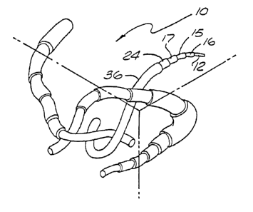
22 In one embodiment of the invention, a substrate
23 generally indicated at 10 may be provided with porous, permeable
24 and anisotropic properties. The substrate 10 is included in an
article generally indicated at 11. The substrate may be formed
26 from discrete elements 12 such as fiber or grains or a mixture
27 of fibers and grains. The discrete elements may have a carbon
28 or ceramic base. By way of illustration, the discrete elements
29 may be formed from a suitable material such as pyrolyzed wool,
rayon, polyacrylonitrile and pitch fibers. Carbonized rayon
31
32
i 3~5~9
1 felt, chopped fibers of carbonized polyacrylonitrile, carbonized
2 rayon cloth made from interwoven carbon fibers, a tape material
3 made of closely woven, carbonized PAN fibers, a macerated
4 material comprising a multiplicity of randomly oriented
pyrolyzed wool fibers and a macerated material havlng a
6 multiplicity of chopped pitch fibers have specifically been
7 used.
9 The substrate can also advantageously be formed from a
slurry comprising granular material such as silicon carbide or
11 graphite. Such granular material can also be mixed with short
12 lengths of high temperature resistant fibers selected from the
13 group consisting of ceramic, pyrolyzed wool, rayon,
14 polyacrylonitrile and pitch. The slurry may also include a
suitable carbonaceous binder such as petroleum pitch, coal tar
16 pitch, furan resins and phenolic resins. The slurry used to
17 form the substrat-e may also comprise short lengths of
18 polyacrylonitrile fibers intermixed with silicon carbide in
19 granular form.
21 The different substrates described above may be formed
22 on a continuous basis or may be formed by cyclic or pulsing
23 techniques. When cyclic or pulsing techniques are used, a
24 sequence of steps is provided under controlled conditions for
limited periods of time and the sequence is repeated more than
26 once. An example is specified in Example 11 in Canadian
27 Patent 1,286,549 issued July 23, 1991, for "Refractory
28 Composite Material and Method of Producing Materlal" and
29 assigned of record to the assignee of record of this
application.
31
32
r
. ~,
.~ , .
, .
''''- ,~ ,
1 3365~9
l The substrate described in the previous paragraphs may
2 be directly coated (Figure 3) with a thin layer 15 of a barrier
3 material and a thin layer 17 of a material impermeable to
4 oxygen, as shown in Figure 2. Bowever, in order to coat the
layers 15 and 17 directly on the substrate 10, the substrate 10
6 ig $nitially shaped preferably to a configuration corresponding
7 to that desired for the finished article. The substrate 10 is
8 then preferably retained in the desired configuration while the
9 layers 15 and 17 are being deposited on the substrate 12. This
retention may be provided by a tool or fixture (not shown) which
ll i~ constructed to retain the substrate 10 in the desired
12 configuration while still providing for the coating of the
13 layers 15 and 17 at every desired position on the substrate.
14 Coating of the layers 15 and 17 on the substrate in this manner
is advantageous in that it is direct and does not require any
16 intermediate preparation of the substrate. ~owever, it
17 generally requires the preparation of special tools and
18 fixtures. Furthermore, it increases the space requirements for
l9 the coating operation because of the use of the tools or
fixtures. It also tends to slow the rate at which the layers 15
21 and 17 are coated on the substrate 10.
22
23 Alternatively, pyrolyzed carbon 16 (Figure 2) may be
24 deposited in a thin layer on the substrate 10, as shown in
Figure 3, before the deposition of the layers 15 and 17 on the
26 substrate. The thickness of this layer may illustratively be
27 two thousand angstroms (2000 A). The pyrolyzed carbon 16
28 facilitates the promotion of a good load transfer between fibers
29 in the substrate, particularly when the article is stressed.
The pyrolyzed carbon 16 also helps to strengthen and stabilize
31
32
.. .... . " .. --~ . .
- - ., . :. ~ ,
..:. ;;'.';.: ~
'~''
133bS59
1 the substrate 10, particularly when the article is subjected to
2 stress. It also enhances the mechanical interface for
3 increasing the surface fracture energy of the composite
i structure defining the article 11, thus enhan-ing the toughness
and flow resistance of the refractory composite article 11.
6.
7 To provide the coating 16 of pyrolyzed carbon on the
8 substrate 10, the substrate may be disposed in a furnace of
9 conventional design. The temperature of the substrate may then
be raised to a suitable temperature such as approximately
11 1800-F. and a vacuum in the order of 15 mm mercury (~g) may be
12 maintained within the deposition chamber. Pyrolyzed carbon may
13 then be deposited about each of the discrete elements 12 in the
14 substrate 10 by flowing methane gas through the porous substrate
for an extended period of time such as about fifty (SO) hours.
16 In this way, the pyrolyzed -arbon encases each of the discrete
17 elements 12 in the substrate 10.
18
19 When the pyrolyzed carbon is deposited on the
substrate 10 in the manner discussed in the previous paragraph,
21 it encases the discrete elements defining the substrate. This
22 is illustrated schematically at 16 in Figure 2. The layer of
23 pyrolyzed carbon 16 is preferably porous, permeable to oxygen
24 and anisotropic. With a density of the substrate on the order
of 0.3 gm/cc and a fiber volume of about fifteen percent (15%)
26 before the deposition of the pyrolyzed carbon 16, the substrate
27 encased with the pyrolyzed carbon may have a density in the
28 order of 0.75 gm/cc. The pyrolyzed carbon 16 serves to position
29 the discrete elements 12 in the substrate 10 and to strengthen
the substrate for handling purposes. In this way, the matrix 24
31
32
.. .. .... ..
. ...
1 33~559
1 can be deposited on the substrate 10 without requiring any tools
2 or fixtures to be used.
4 The pyrolyzed carbon 16 can be deposited on the
substrate by other techniques than those discussed above. For
6 example, the substrate 10 can be coated with any suitable and
7 conventional type of resin such as a phenolic designated by
8 Monsanto Chemical Company as Monsanto 1008. As a first step,
9 the phenolic may be dissolved in a solvent such that it is
fluid. The solvent may illustratively be methylethylketone.
11 The substrate 10 may then be coated with the phenolic and
12 partlally polymerized so that it is dry to the touch. Patterns
13 of the desired shape can then be cut from the substrate 10 or
14 the substrate can be heated to a temperature of at least 160-F,
compressed and then cut to the desired shape. The patterns in
16 the desired shape ma~ then be placed in a mold and heated to a
17 suitable temperature such as approximately 350-F to cure the
18 phenolic. The patterns may then be cured at a temperature above
19 350-F to stabilize the system.
21 The phenolic is then pyrolyzed at a temperature of
22 approximately 1600-F. to decompose it to carbon, its elemental
23 form. One reason for the pyrolysis is to prevent the substrate
24 from thereafter emitting gases when it is heated. However, the
discrete elements 12 are retained in position by the pyrolyzed
26 carbon 16 which is disposed in the interstices between the
27 discrete elements, as shown in Figure 4. The deposition of the
28 pyrolyzed carbon 16 in the interstices between the discrete
29 elements 12 is illustrated schematically in Figure 2. The
combination of the discrete elements 12 and the pyrolyzed carbon
31
32
. ;.
- 1 336~59
1 16 in the interstices is porous, permeable to oxygen and
2 anisotropic-
4 When the binder constituting the phenolic is pyrolyzed
as discussed in the previous paragraph, it loses approximately
6 half of its mass and it shrinks and cracks. In spite of this,
7 the pyrolyzed carbon is able to hold the discrete elements 12 in
8 position in the substrate and to impart strength to the
9 substrate. The substrate 10 is then heated to a temperature of
approximately 2200-F. for a relatively short period of time to
11 impart a final shrink and pyrolyzation to the binder.
12
13 Polyurethane or polyethylene can be 1ncluded ~n the
14 ~ phenolic binder before the binder is cured and pyrolyzed as
discussed in the previous paragraphs. When the substrate 10 and
16 the binder are then heated to approximately 1600~F., the
17 polyurethane or polyethylene vaporizes and facilitates the
18 formation of tunnels in the substrate. As will be disclosed in
19 detail subsequently, the-tunnels are effective in providing
paths for depositing the barrier layer 15, the impermeable layer
21 17 and the matrix 24 on the substrate 10 as by chemical vapor
22 deposition.
23
24 Instead of using a wet binder to coat the discrete
elements 12, a dry binder may be used. Dow Corning Polycar-
26 bosilane 6-2330 is illustrative. This is a dry resin which may
27 be mixed with methylethylketone to provide a fluid mixture with
28 which to work. This material has properties of becoming
29 partially polymerized at room temperatures. The material is
mixed with the substrate and is then heated to a temperature of
31
32 *Trade mark
1~36559
1 approximately 1600-F. to pyrolyze the binder. The material is
2 subsequently heated to a temperature of approximately 2200-F. to
3 provide it with a final pyrolyzation and shrink.
Sodium silicate or colloidal alumina can also be used
6 as binders. The substrate 10 may be dipped into sodium silicate
7 in liquid form and may then bè heated. The sodium silicate
8 flows along the lengths of the discrete elements 10 and tends to
9 congregate or agglomerate at the interstices between the
discrete elements. The formation of layers of material at the
11 interstices between the fibers of the substrate 10 is shown in
12 Figures 4 and 5.
13
14 As will be appreciated, the characteristics of the
sub~trate can be considerably varied without departing from the
16 scope o, the invention. For example, when fibers are used in a
17 woven form, the relative numbers of threads in warp and woof
18 can be var$ed in great proportions and the spacing between the
19 threads can also be varied considerably.
21 A suitable element such as boron can be applied to the
22 substrate 10 in compound form with other elements such as carbon
23 and/or nitrogen to form the intermediate layers 15 and 17
24 between the substrate 10 and the matrix 24. These intermediate
layers 15 and 17 may be deposited on the substrate 10 before the
26 deposition of the matrix 24, as shown in Figure 5. The
27 intermediate layers 15 and 17 may also be deposited on the
28 pyrolyzed layer 16 as shown in Figure 4.
29
31
32
-- 10 --
: . ;. .. . .
1 33b559
1 The intermediate layer 15 may constitute a suitable
2 material such as boron carbide (B4C) and the intermediate
3 layer 17 may constitute a suitable material such as boron
4 nitride (BN). The boron carbide serves as a barrier layer to
inhibit the boron from the boron nitride from infiltrating or
6 diffusing into the pyrolytic layer 16. The boron nitride
7 provides a layer impermeable to oxygen. This prevents oxygen
8 from decomposing the carbon in the substrate 10 and the
9 pyrolyzed layer 16. The layers 15 and 17 may encase the
pyrolytic material 16 (Figure 2) or may be deposited on the
11 interstices of the pyrolytic material (~igure 4).
12
13 The pyrolitic layer 16, the barrier layer 15 and the
14 impermeable layer 17 may be deposited in thin layers each having
a substantially uniform thickness. For example, the thickness
16 of each of the layers 16, 15 and 17 may be on the the order of
17 approximately two thousand Angstroms (2000 A). The layers 15
18 and 17 may encase the pyrolytic layer 16 when the pyrolytic
19 layer encases the substrate 12. Similarly, the layers 15 and 17
may be disposed in the interstices of the pyrolytic layer 16 on
21 the discrete elements 12 when the pyrolytic layer is disposed on
22 the interstices of the discrete elements.
23
24 The pyrolytic layer 16, the layer 15 of the barrier
material and the layer 17 of the impermeable material may be
26 formed by chemical vapor infiltration techniques. These
27 techniques are available because the discrete elements 12 in the
28 substrate 10 occupy approximately only thirty five percent (35~)
29 to forty percent (40~) of the volume of the substrate. Because
of the relatively low volume occupied by the discrete elements
31
32
,. . ~
.
. ~ - ~ .,: . . ,
~ ,~
1 336559
l 12, the gases forming each of the layers 16, 15 and 17 are able
2 to infiltrate into the interior of the substrate and produce
3 depositions throughout the volume of the substrate.
The uniform depositions of the layers 16, 15 and 17 on
6 the substrate 10 are facilitated by subjecting the chemical
7 vapors in the infiltration process to elevated temperatures and
8 to pulsating pressures (Figure 8) and by further subjecting the
9 gases to periodic reversals in the direction of flow through the
substrate. For example, the pyrolytic layer 16 may be produced
ll at a temperature of approximately 1015C. and may be subjected
12 to pressures between approximately ten torr (10 torr) and
13 approximately eighty torr (80 torr) at a rate of approximately
14 one and one half torr (1.5 torr) per second. The typical dwell
time at the bottom pressure may be approximately thirty (30) to
16 approximately sixty (60) seconds. The typical dwell time at the
17 top pressure may be approximately five (5) seconds. The
18 direction of the flow of the chemical vapors may be reversed
l9 approximately every two (2) minutes or less.
21 In depositing the layer 16 on the substrate 10,
22 methane (CH4) may be flowed through the substrate at a rate of
23 approximately twelve and three tenths (12.3) cubic centimeters
24 per square centimeters per minute (Figure 8). The methane may
be mixed with argon (Ar), which is flowed through the substrate
26 10 at a rate of approximately nine and one quarter (9.25) cubic
27 centimeters per square centimeter per minute. Argon is neutral.
28 It imparts energy to the methane and controls the rate at which
29 carbon from the methane is deposited on the substrate 10. Other
neutral ga~es such as helium can be used instead of, or with,
31
32
12 -
'.
1 336559
l the methane to deposite the pyrolytic carbon 16 on the substrate
2 10.
4 The pressure cycling technique discussed above between
pressures such as ten torr (10 torr) and one hundred torr (100
6 torr) is used to augment substantially the diffuse mass
7 transport process which is at work in a steady state chemical
8 vapor infiltration (CVI) process. With such techni~ues,
9 infiltration depths of at least fifty mils (50) have been
achieved. This has meant the difference between an impractical
ll (the steady-state) process and a practical (the
12 pressure-pulsating) process.
13
14 The increased infi}tration of the methane and argon
into the substrate 10 to form the pyrolytic layer 16 may be seen
16 from the following analysis. As the pressure of the gases in
17 the chemical vapor infiltration (CVI) process increases, the
18 pressure external to the substrate 10 increases on a
l9 corresponding basis. ~owever, the pressure of the gases within
the substrate 10 does not increase as fast as the pressure of
21 the gases outside of the substrate. This may result in part
22 from the fact that the pores in the substrate 10 are relatively
23 small so that the pressure of the gases within the substrate 10
24 cannot follow the pressure of the gases outside of the substrate
as the pressure of the gases increases. This differential of
26 pressure acts upon the methane and argon gaseous reactants to
27 produce a flow of such material into the innermost reaches of
28 the substrate 10 and to produce a deposit of the carbon there.
29 This provides for a substantially uniform deposition of the
carbon not only on the surface of the substrate 10 but also
31 within the interior of the substrate.
32
- 13 -
. . .
~ . . ~
1 336559
1 Following the introduction into the furnace or chamber
2 of the methane and the argon and the pulsation of the pressure
3 of the gases in the furnace or chamber, the gases may be
4 withdrawn from the furnace by producing a mild vacuum. Freah
gases containing methane and argon may be then introduced into
6 the furnace for flow in an opposite direction through the
7 substrate 10. The fresh gases may then be pulsed in a manner
8 similar to that described above. This process may be repeated
9 through a number of cycles for a flow`of the gases in one
directionr and alternately in an opposite direction, through the
11 substrate 10 until the pyrolytic material 16 has been formed
12 with the desired thickness.
13
14 The periodic introduction of gases into the furnace
and subse~uent exhaustion of these gases from the furnàce
16 provide certain important advantages. As will be seen, the
17 composition of the gases introduced to the furnace changes with
18 time because of the chemical reactions in the gases and because
19 of the exhaustion of the gase,s as the gases are chemically
reacted to produce the pyrolytic layer 16. This causes the
21 properties of the pyrolytic layer 16 to vary with time. By
22 exhausting these gases from the furnace after a relatively short
23 period of time and subsequently introducing a new supply of such
24 gases into the furnace, relatively constant characteristics can
be provided for the pyrolytic layer 16 along th,e various
26 microscopic dimensions of the article being processed.
27
28 The reversal in the direction of flow of the methane
29 and the argon also offers certain advantages. It assures that
the thickness of the pyrolytic layer 16 will be substantially
31
32
- 14 -
- ','
.~ .
' ;'. ' ". '' ' ' : " " . ~ . , ' '
~--.
~ "
1 336~59
1 uniform throughout the substrate. If the direction of flow of
2 the methane and the argon i8 not reversed, the pyrolytic coating
3 16 may have a greater thickness at the end at which the gases
4 enter the substrate than at the end at which the gases leave the
substrate. By reversing the direction of flow of the gases, any
6 such difference in the thickness of the pyrolytic layer 16 at
7 the opposite ends of the substrate 10 is compensated.
8 Furthermore, the thickness of the deposition at the center of
9 the substrate 10 is also enhanced reversing the direction of the
flow of the gases,
11 .
12 The barrier layer 15 is produced by a chemical vapor
13 infiltration process similar to that described above. However,
14 the temperature~of the process may be approximately 900-C. and
the gases used may be a mixture of hydrogen (H2), argon (Ar),
16 methane (CH4) and boron trichloride (BC13). The hydrogen
17 may be flowed through the substrate 10 at a rate of
18 approximately three and seven tenths (3.7) cubic centimeters per
19 square centimeter per minute, the argon at a rate of
approximately nine and one quarter (9.25) cubic centimeters per
21 square centimeter per minute, the methane at a rate of
22 approximately one and fifty four hundred hundredths (1.54) cubic
23 centimeters per square centimeter per minute and the boron
24 trichloride at a rate of approximately three and one tenth (3.1)
cubic centimeters per square centimeter per minute (Figure 8).
26 The gases may be pulsed, and the direction of the flow of the
27 gases may be reversed, in a manner similar to that discussed
28 above for the deposition of the pyrolytic layer 16 on the
29 substrate 10.
31
32
.. . .
, . ........... ~ , ~. . . ,, :
i;,,,'
1 33655~
1 As the gases pas~ through the substrate 10, the boron
2 in the boron trichloride and the carbon in the methane combine
3 to produce boron carbide (B4C). The hydrogen from the methane
4 and the chlorine from the boron trichloride are exhausted as
gases from the furnace. The hydrogen introduced as a separate
6 gas into the furnace affects the chemical and heat balance of
7 the gases introduced to the furnace. The amount of the hydrogen
8 introduced into the furnace can be varied to affect this
9 chemical and heat balance. The argon has the same affect as
discussed above with respect to the pyrolytic layer 16.
11
12 The impermeable layer 17 is also produced by chemical
13 vapor infiltration techniques in a manner similar to that
14 discussed above. ~owever, the permeable layer 1,7 may be
produced at a temperature of approximately 875-C. and may be
16 produced by a mixture of argon (Ar), boron trichloride (BC13)
17 and ammonia (NH4). THe argon may be passed through the
18 substrate at a rate of approximately fifteen and four tenths
19 (15.4j cubic centimeters per square centimeter per minute, the
boron chloride at a rate of approximately one and four tenths
21 (1.4) cubic centimeters per square centimeter per minute and the
22 ammonia at a rate of approximately seven tenths (~.7) per cubic
23 centimeter per minute (Figure 8). The variations in pressure of
24 the gases, and the reversal in the direction of the flow of the
gases, may be as discussed above with respect to the pyrolytic
26 layer 16.
27
28 The boron from the boron trichloride and the nitrogen
29 from the ammonia combine to form boron nitride (~N) which is
deposited on the substrate to form the impermeable layer 17.
31 The chlorine in the boron trichloriae and the hydrogen in the
32
- 16 -
.
1 33~559
1 ammonia then pass through the furnace as molecules of gas. The
2 argon is included in the mixture for the reasons discussed above
3 with re~pect to the pyrolytic layer 16.
Figure 6 shows the advantages of providing the layers
6 16, 15 and 17 on the substrate 10. As will be seen in Figure 6,
7 th`e sputter time for removing the layers 16, 15 and 17 on the
8 substrate 10 is shown in minutes on the horizontal axis. Thus,
9 approximately thirty (30) minutes is shown in Figure 6 as the
sputter time for removing the pyrolytic layer 16 on the
ll substrate 10; approximately twenty t20) minutes as shown as the
12 sputter time for removing the barrier layer 15 on the substrate;
13 and approximately five (5) minutes is shown as the sputter time
14 for removing the impermeable layer 17 on the substrate. In
lS effect, the horizontal axis indicates the progressive positions
16 in each of the layers 16, 15 and 17 when a sectional cut is made
17 in such layers. It should be noted that sputter time to remove
18 each layer may not be relatively proportional. Each of the
~9 layers 17, 15 and 16 may be removed by bombarding the layer with
argon atoms.
21
22 In Figure 6, the atomic percent (~) of different
23 materials is shown on the vertical axis. As will be seen, the
24 relative amount of boron in the layers 16, 15 and 17 is shown by
a curve whose positions are indicated by squares. Figure 6
26 shows that the amount of boron in the layer 17 and the portion
27 of the layer 15 adjacent the layer 17 remains constant.
28 However, the amount of boron in the layer 15 starts to decrease
29 as the positions of the layer progressively approach the layer
16, and the amount of boron continues to decrease with
31 progressive positions into the layer 16. This tends to show
32
- 17 -
. .
1~3655q
1 that the barrier layer 15 is effective in inhibiting the
2 infiltration into the layer 16 of the boron in the layer 17.
3 For example, although the atomic percent of the boron in the
4 layer 17 and most of the layer 15 is approximately sixty percent
(60%), the atomic percent of the boron in the pyrolytic layer 16
6 i8 approximately fifty percent (50%) at the boundary with the
7 layer 15 and is less than twenty percent (20%) at the boundary
8 with the substrate 10. It is desirable to minimize the amount
9 of the boron in the pyrolytic layer 16 because the boron tends
to weaken the pyrolytic layer and to inhibit the action of the
11 pyrolytic layer in providing for a shear of the matrix 24
12 relative to the substrate 10 with changes in temperature.
13
14 Figure 6 also shows that the atomic percentage of
nitrogen is slightly greater than thirty percent (30%) through
16 most of the impermeable layer 16 and decreases quickly to a
17 level significantly less than ten percent (10%) through most of
18 the barrier layer 15 and all of the pyrolytic layer 16. The
19 atomic percentage of the nitrogen is plotted as plus (+)
positions in Figure 6.
21
22 The atomic percentage of carbon is plotted in Figure 6
23 by diamond positions. As will be seen, the atomic percentage of
24 carbon is less than ten percent (10%) throughout most of the
thickness of the impermeable layer 17 and rises to a level of
26 approximately twenty percent (20%) at the boundary with the
27 barrier layer 15. The atomic percentage of carbon continues to
28 rise to a percentage between approximately thirty percent (30%)
29 and forty percent (40%) in the barrier layer 15 and remains at
this percentage throughout most of the thickness of the barrier
31 layer. The atomic percentage of carbon then rises progressively
32
- 18 -
, . ... . .
- : . .
1 336.559
1 to a percentage in excess of eighty percent (80~) at the
2 boundary between the pyrolytic layer 16 and the substrate 12.
4 As shown in Figure 6, the boron from the impermeable
layer 17 i8 unable to diffuse to any significant extent into the
6 pyrolytic layer 16. This may be because the boron carbide in
7 the barrier layer 15 has four (4) carbon atoms to every boron
8 atom. The vast preponderance of the carbon atom~ in the barrier
9 layer 15 may thus serve as a trap for the boron atoms to inhibit
any material diffusion of the boron atoms through the barrier
11 layer 15 into the pyrolytic layer 16. The action of the boron
12 carbide in inhibiting the diffusion of boron from the boron
13 nitride into the pyrolytic layer 16 may also result from the
14 fact that the carbon in the boron carbide is compatible with the
carbon in the pyrolytic layer 16.
16
17 The barrier layer 15 also provides another significant
18 advantage. As the oxygen from the atomosphere leaks into the
19 barrier layer 15, it attacks the boron carbide and causes boron
suboxideS to be produced. These boron suboxides are volatile
21 and migrate through the oxygen leak path toward the atmosphere.
22 The suboxides meet the oxygen leaking into the barrier layer 15
23 from the atmosphere and cause the suboxides to become fully
24 oxidized to boron oxide (B2O3). The boron oxide tends to
plug the leak path so that oxygen cannot continue to leak
26 through this path to the barrier layer 15. By plugging such
27 leak paths, oxygen is unable to leak to the pyrolytic layer 16
28 and the substrate 10. This is important because the oxidation
29 of the pyrolytic layer 16 and the substrate 10 tends to weaken,
and ultimately to destroy, the pyrolytic layer and the
31
32
- 19 -
. . . . - .:
~ - ~
1 336559
1 substrate. The self plugging feature of boron carbide tends to
2 occur at relatively moderate temperatures such as approximately
3 1300-C. and at temperatures even lower than 1300-C.
S Other materials than boron carbide can be used for the
6 barrier layer 15 and other materials than boron nitride can be
7 used for the impermeable layer 17. For example, silicon carbide
8 can be used in place of boron carbide for the barrier layer 15
9 and silicon nitride can be used in place of boron nitride for
the impermeable layer 17. The silicon carbide is effective as a
11 barrier material in preventing the diffusion of silicon from the
12 silicon nitride into the pyrolytic layer 16 and the substrate
13 10. The silicon nitride is effective as a material impermeable
14 tD oxygen. ~owever, the combination of silicon carbide for the
barrier material and silicon nitride for the impermeable
16 material is not as advantageous as the combination of boron
17 carbide for the barrier material and boron nitride for the
18 impermeable material because the silicon carbide does not have
19 the properties of becoming self plugged when subjected to oxygen
leakage paths. Rhenium or irridium may also be used as the
21 barrier layer 15 to control the diffusion of boron into the
22 pyrolytic layer 16 but they also do not have the advantages
23 discussed above for boron carbide.
24
Figure 7 shows a cross section of an article
26 constructed as discussed above and including the substrate 10,
27 the pyrolytic layer 16, the barrier layer 15 containing boron
28 carbide and the impermeable layer 17 containing boron nitride.
29 The cross section shown in Figure 6 has been obtained through
the use of Auger Electron Spectroscopy and does not represent
31
32
- 20 -
-- CA 1 33655~
the actual thickness of the different layers in the article.
3 The combination of the barrier layer 15 and the
4 impermeable layer 17 is also advantageous when the substrate 10
is formed from discrete elements made from a material such as
6 silicon carbide. One type of such discrete elementa may
7 constitute ~Nicalon" ceramic fibers. When the impermeable
8 material such as boron nitride is disposed on such a substrate
9 without including the barrier layer 15, the boron from the boron
nitride tends to diffuse into the "Nicalon" ceramic fibers in
11 the substrate 10 and severly damage such fibers and sharply
12 reduce their mechanical properties. The inclusion of the layer
13 15 of boron carbide between the substrate 10 and the impermeable
14 layeri17 materially limits the diffusion of the boron from the
impermeable layer into the substrate.
16
17 In addition to the combinations discussed above for
18 the layers 15 and 17, other combinations may also be used. For
19 example, when the pyrolytic layer 16 is included, the barrier
layer 15 may constitute silicon carbide and the impermeable
21 layer 17 may constitute boron nitride. Alternatively, the
22 barrier layer 15 may constitute silicon nitride (Si3N4) and
23 the impermeable layer 17 may constitute boron nitride.
24
Instead of using boron trichloride to form the boron
26 carbide and boron nitride layers, other materials such as boron
27 flouride (BF3) or boron hydroxide (B2~) may be used.
Hydrocarbons other than methane may also be used to produce the
29 pyrolytic layer 16 and the~;boron carbide in the barrier layer
31 *Trade mark
32
21 -
: .~
,' .
" ~
1 33~559
1 15. When the barrier layer constitutes silicon carbide and/or
2 the impermeable layer constitutes silicon nitride (Si3N4),
3 materials such as methyltrichlorosilane, dichlorosilane and
4 other organometallics may be used.
6 The matrix 24 deposited on the impermeable layer 17
7 does not have any significant chemical or mechanical bond with
8 the substrate 10 or the pyrolytic layer 16. Because of this,
9 ~ncreased surface fracture energy (toughness) is produced
between the substrate 10 and the matrix 24. The matrix 24 also
11 has a significantly different coefficient of thermal expansion
12 than the substrate 10. As a result, the matrix 24 i9 free to
13 move relative to the substrate 10 with changes in temperature.
14 This is particularly important because of the considerable range
of temperatures (in the thousands of degrees Fahrenheit) in
16 which articles formed from the refractory material of this
17 invention are expected to work. The matrix 24 encases the
18 impermeable layer 17 when the coating encases the substrate 10.
19 The matrix 24 is disposed in the interstices of the discrete
elements 12 when the impermeable layer 17 is disposed in such
21 interstices. The matrix 24 may have a suitable thickness such
22 as approximately six thousand Angstroms (6000 A) when the layers
23 16, 15 and 17 have thicknesses such as two thousand Angstroms
24 (2000 A).
26 The matrix 24 may be formed from a suitable material
27 consisting of a metal and a material providing negatively
28 charged ions. Preferably the matrix 24 may be formed from a
29 material selected from a group consisting of silicon nitride,
silicon carbide, silicon oxide and silicon boride. The matrix
31
32
- 22 -
..... ... . . . .
- ~
.
... , .. , . . . . -
1 336559
1 24 may be preferably formed from silicon carbide. Silicon
2 carbide i5 advantageous because it is hard and tough and
3 provides good protection to the substrate. The matrix may also
4 be formed from other materials such the oxides, nitrides,
carbides and borides of hafnium, zirconium, tantalum, tungsten
6 and molybdenum.
8 To apply the matrix 24 on the substrate 10, the
9 substrate may be disposed in a furnace and heated to a
temperature in the range of about 1350-F. to 2500-F. Preferably
11 the substrate 10 is heated to a temperature of about 1800-F. in
12 a mild vacuum. This temperature is intermediate in a preferred
13 temperature range of about 1600-F. to 2000-F. A suitable gas
14 cont~ining silicon and carbon may then be passed through and
over the substrate 10 in the furnace. For example, suitable
16 gases such as ~ethyltrichlorosilane, dimethyldichlorosilane and
17 trimethylchlorosilane may be used. The gas may be allowed to
18 fill the furnaces to a pressure between about 0.01 and 0.6
19 atmospheres.
21 Following the introduction into the furnace of the
22 gases containing the silicon and the carbon, the gases are
23 withdrawn from the furnace by producing a mild vacuum. New
24 gases containing silicon and carbon are then introduced into the
furnace. This process is repeated through a number of cycles
26 until the matrix has been formed with the desired thickness.
27 The temperature of the substrate 10 may be intermittently raised
28 to about 2700-F to produce a dimensional stability between the
29 silicon carbide in the matrix 24 and the pyrolyzed carbon 16 on
the substrate 10. The direction of the flow of gases through
31
32
. . , . , , -:
i ~JVJJ~ rA 1 336559
~,~
the substrate 10 in each alternate cycle may be reversed in a
2 manner similar to that discussed above. A number of specific
3 examples for the production of the matrix 24 are disclosed in
4 Canadian Patent 1,286,549 issued July 23, 1991, for
~Refractory Composite Material and Method of Producing
6 Material" and assigned of record to the assignee of record of
7 this application.
9 The particular chemical constituents produced to form
the matrix material are dependent upon certain parameters
11 including temperature, pressure, gases used, flow rate of the
12 gases and mass rate of the gases. The mass rate is in turn
13 dependent upon such factors as flow rate and the particular
14 gases used.
16 Other gases can be included in the chemical vapor
17 deposition in addition to those specified above. For example,
18 gases of argon and helium can be included in the gases
19 introduced to the furnace. Both argon and helium are neutral.
They impart energy to the gases in the furnace and they control
21 the rate at which the matrix 24 is deposited on the sub~trate.
22 They also control the characteristics of the deposition.
23
24 The relative amount of hydrogen in the gases can also
be varied. The relative amount of hydrogen affects the chemical
26 and heat balance of the gases introduced to the furnace. As a
27 result, the rélative amount of hydrogen in the gases affects the
28 characteristics of the deposition. For example, when the
29 furnace is maintained at a ~relatively low temperature and a
considerable amount of hydrogen is introduced into the furnace,
31
32
- 24 -
C , ' ~
, ~"
e
I 33655~
1 an excess of silicon above the stoichiometric ratio tends to be
2 deposited. Furthermore, even slight changes in temperature can
3 affect the hardness of the deposition. By way of illustration,
4 a change of about 10-F. in the furnace can produce a change of
as many as 1000 points in Vickers hardness out of a range of
6 approximately 1300-4400 in Vickers hardness. Thus, the mixture
7 of a small amount of hydrogen with the gases producing the
8 matrix 24 may have a significant effect on the hardness of the
9 matrix which is produced.
11 Boron can also be included in the gases introduced
12 into the furnace to obtain the chemical vapor deposition of the
13 matrix 24 on the impermeable layer 17. The inclusion of boron
14 in the mixture enhances the tendency of the matrix 24 produçed
from the deposition of the gases to be forgiving. This enhances
16 the tougnness of the matrix 24 and the ability of the matrix to
17 withstand strain. The boron in the mixture acts as a getter.
18 It accumulates the material of the matrix 24, such as silicon
19 carbide, from active sites and causes the silicon carbide from
such active sites to be sintered together. Without the
21 inclusion of the boron, the silicon carbide tends to be
22 deposited at the active siteæ. Nominally about two percent (2%)
23 by weight of the boron may be included in the mixture.
24 Preferably the range of boron is about one percent (1%) to three
(3%) by weight. Preferably less than five percent (5%) of boron
26 by weight is included in the mixture.
27
28 Other gases may be used in producing a chemical vapor
29 deposition of the matrix 24 on the substrate 10. For example, a
mixture of silicon tetrachloride and methane may be used. ~he
31
32
.. . .
.
-
:
I 33~559
1 mixture of silicon tetrachloride and methane tends to produce a
2 deposition of sil$con carbide to form the matrix. Such a
3 mixture may require a greater amount of energy to produce the
4 matrix than some of the gases specified above.
6 As will be appreciated, the substrate 10 disposed in
7 the furnace can be pre-heated to impart energy to the gases in
8 the furnace for en~ancing the production of a chemical reaction
9 of the gases. The resultant deposition of the material such as
silicon carbide on the substrate 10 to form the matrix 24 has
11 first characteristics. Alternatively, the substrate does not
12 have to be pre-heated before being introduced into the furnace.
13 In either case, the gases receive sufficient kinetic energy to
14 produce chemical reactions when they collide. Particles of
silicon carbide are produced as a soot in free space as a result
16 of such collisions and as a result of the chemical reactions
17 occurring during the collisions.
18
19 The characteristics of the silicon carbide produced
without pre-heating the substrate 10 are different from the
21 characteristics of the silicon carbide produced by pre-heating
22 the substrate. This results in part from differences in
23 microscopic structure of the grains of silicon carbide deposited
24 on the substrate. As will be appreciated, in addition to
forming the matrix 24 by the two separate techniques discussed
26 above, the matrix 24 can be formed by a combination of such
27 techniques to provide the matrix with a blend of character-
28 istics.
29
31
32
- 26 -
r .~ ,~. ...... .. . .
- .:
1 336559
1 When the matrix 24 is formed from a suitable material
2 such as silicon carbide in the manner described above, it tends
3 to receive microscopic cracks in its periphery. These cracks
4 are advantageous because they tend to impart resilience and
flexibility to the matrix, particularly when the matrix i8
6 subjected to stresses. The cracks are disadvantageous because
7 they increase the amount of the surface exposed to oxygen. As a
8 result, there tends to be an increase in the rate at which the
9 matrix 24 is oxidized.
11 An impermeable coating 36 may be disposed on the
12 matrix 24 to cover the matrix and inhibit the oxidation of the
13 matrix. This is particularly important when the matrix 24 has
14 the microscopic cracks as discussed above. The coating 36 may
be formed from a suitable material such as silicon oxide.
16 Silicon oxide is advantageous because it is hard and because it
17 is impermeable to oxygen. For example, since the silicon oxide
18 already includes oxygen, it cannot be oxidized by the oxygen in
19 the air. The silicon oxide has substantially the same
coefficient of thermal expansion as the silicon carbide in the
21 matrix 24. ~ecause of this, it has properties of moving with
22 the matrix 24 with changes in temperature.
23
24 The coating 36 of silicon oxide may be deposited on
the matrix 24 under substantially the same conditions of various
26 parameters such as temperature pressure and flow rate and
27 direction reversal as those used to deposit the matrix 24 of
28 silicon carbide on the substrate. The deposition of the silicon
29 oxide on the matrix 24 may also be accomplished by liquid spray
or immersion such as discussed above. Other materials such as
31
32
- 27 -
... . . . .. . . . . .
, ' ' : . ,' ' - ' ~ '-................ . '
1 336559
l silicon nitride may be provided as the layer 36. Furthermore,
2 other materials such as metal oxides, metal nitrldes, metal
3 silicldes, metal borides and metal carbides may also be used as
4 the layer 36. The layer 36 may be viscous.
6 Figure 1 illustrates a schematic diagram of a furnace,
7 generally indicated at 40, which may be used to produce the
8 composite materials described above. The furnace 40 includes an
9 enclosure 42 having an inlet 44 and an outlet 46. Gases, such
as those used to produce a chemical vapor deposition of the
ll matrix 24 on the substrate lO, are introduced into the furnace
12 40 through the inlet 44. The gases flow downwardly along the
13 walls defining the enclosures as indicated by arrows 48. The
14 gases then flow upwardly along the enclosure 42, as indicated by
arrows 52. Since the path defined by the arrows 48 and 52
16 within the furnace 40 is relatively long, the gases have a
17 considerable opportunity to become heated to the temperature of
18 the furnace heaters 50. The gases then flow within the space
l9 defined by the enclosure 42 and flow from the furnace 40 through
the outlets 46. During the flow of the gases within the
21 enclosure 42, the gases have an opportunity to become deposited
22 on the article, such as the substrate 10, in which a deposition
23 is to be provided. When the direction of gaseous flow is to be .
24 reversed as discussed above, the furnace 40 may be disposed to
cyclically close and open opposing inlets 44 and outlets 46 and
26 gases may then be passed through the article 11 in opposite
27 directions to produce the successive layers defining the
28 article.
29
31
32
- 28 -
. .
~ 336559
1 Although this invention has been disclosed and
2 illustrated with reference to particular embodiments, the
3 principles involved are susceptible for use in numerous other
4 embodiments which will be apparent to persons skilled in the
art. The invention is, therefore, to be limited only as
76 indicated by the scope of the appended claims.
11
12
13
14
16
17
18
19
21
22
23
24
26
27
28
29
31
32
- 29 -