Note: Descriptions are shown in the official language in which they were submitted.
1 336S~2
-- 1 --
Electrostatic Liquid Spray Applicat_on of Coatinqs
with Supercritical Fluids as ~iluents
and Sprayinq from an Ori ice
Field of the Invention
This invention relates in general to a
process and apparatus for coating substrates. More
particularly, this invention is directed to a
process and apparatus for coating substrates by a
liquid spray in which 1) supercritical fluid, such
as supercritical carbon dioxide fluid, is used as a
viscosity reduction diluent for coating formulations
and 2) the mixture of supercritical fluid and
coating formulation is passed under pressure through
an orifice into the environment of the substrate to
form the liquid spray, and 3) the liquid is
electrically charged by a high electrical voltage
relative to the substrate.
Background of the Invention
Coating formulations are commonly applied
to a substrate by passing the coating formulation
under pressure through an orifice into air in order
to form a liquid spray, which impacts the substrate
and forms a liquid coating. In the coatings
industry, three types of orifice sprays are commonly
used; namely, air spray, airless spray, and air-
assisted airless spray.
Air spray uses compressed air to break up
the liquid coating formulation into droplets and to
propel the droplets to the substrate. The most
common type of air nozzle mixes the coating
formulation and high-velocity air outside of the
nozzle to cause atomization. Auxiliary air streams
.
D-15,997
~ - 2 - 1336662
are used to modify the shape of the spray. The
coating formulation flows through the liquid orifice
in the spray nozzle with relatively little pressure
drop. Siphon or pressure feed, usually at pressures
less than 18 psi, are used, depending upon the
viscosity and quantity of coating formulation to be
sprayed.
Airless spray uses a high pressure drop
across the orifice to propel the coating formulation
through the orifice at high velocity. Upon exiting
the orifice, the high-velocity liquid breaks up into
droplets and disperses into the air to form a liquid
spray. Sufficient momentum remains after
atomization to carry the droplets to the substrate.
The spray tip is contoured to modify the shape of
the liquid spray, which is usually a round or
elliptical cone or a flat fan. Turbulence promoters
are sometimes inserted into the spray nozzle to aid
atomization. Spray pressures typically range from
700 to 5000 psi. The pressure required increases
with fluid viscosity.
Air-assisted airless spray combines
features of air spray and airless spray. It uses
both compressed air and high pressure drop across
the orifice to atomize the coating formulation and
to shape the liquid spray, typically under milder
conditions than each type of atomization is
generated by itself. Generally the compressed air
pressure and the air flow rate are lower than for
air spray. Generally the liquid pressure drop is
lower than for airless spray, but higher than for
air spray. Liquid spray pressures typically range
D-15,997
_ 3 _ 1 336662
from 200 to 800 psi. The pressure required
increases with fluid viscosity.
Air spray, airless spray, and air-assisted
airless spray can also be used with the liquid
coating formulation heated or with the air heated or
with both heated. Heating reduces the viscosity of
the liquid coating formulation and aids atomization.
Electrostatic forces are commonly utilized
with orifice sprays such as air spray, airless
spray, and air-assisted airless spray to increase
the proportion of liquid coating that is deposited
onto the substrate from the liquid spray. This is
commonly referred to as increasing the transfer
efficiency. This is done by using a high electrical
voltage relative to the substrate to impart a
negative electrical charge to the liquid. The
substrate is electrically grounded. This creates an
electrical force of attraction between the liquid
spray droplets and the substrate, which causes
droplets that would otherwise miss the substrate to
be deposited onto it. When the electrical force
causes droplets to be deposited on the edges and
backside of the substrate, this effect is commonly
referred to as wrap around. The substrate should be
electrically conducting or be given a conducting
surface before being sprayed.
The liquid can be electrically charged at
any stage of the spray formation process. It can be
charged by applying high electrical voltage and
electrical current 1) within the spray gun, by
direct contact with electrified walls or internal
electrodes before passing through the orifice; 2) as
D-15,997
1 336662
-- 4 --
the liquid emerges from the orifice, by electrical
discharge from external electrodes located near the
orifice and close to the spray; or 3) away from the
orifice, by passing the liquid spray through or
between electrified grids or arrays of external
electrodes before the spray reaches the substrate.
Electrically charging the liquid as it
emerges from the orifice is widely used. Usually a
short sharp-pointed metal wire, which extends from
the spray nozzle to beside the spray, is used as the
electrode. When a high electrical voltage is
applied to the electrode, electrical current flows
from the point of the electrode to the liquid spray,
which becomes charged. This method is used for air
spray, airless spray, and air-assisted airless spray
guns. It is used for both hand spray guns and
automatic spray guns. Generally the electrical
voltage ranges from 30 to 150 kilovolts. Coating
formulations that are sufficiently conductive will
leak electrical charge through the fluid to the
material supply system; these systems must be
isolated from electrical ground so that the system
itself becomes electrified. For safety reasons, the
voltage of hand spray guns is usually restricted to
less than 70 kilovolts and the equipment is designed
to automatically shut off the voltage when the
current exceeds a safe level. Generally for hand
spray guns the useful range of electrical current is
between 20 and 100 microamperes and optimum results
are obtained with coating formulations that have
very low electrical conductivity, that is, very high
electrical resistance.
D-15,997
1 :~36~5~
-- 5 --
U. S. Patents 3,556,411; 3,647,147;
3,754,710; 4,097,000; and 4,346,849 disclose spray
nozzles and tips for use in airless spray, including
designs and methods of manufacture and methods of
promoting turbulence in the atomizing fluid.
U. S. Patent 3,659,787 discloses a spray nozzle and
use of electrostatics for airless spray. U. S.
Patents 3,907,202 and 4,055,300 disclose spray
nozzles and use of electrostatics for air-assisted
airless spray. None of these patents uses
supercritical fluids as diluents to spray coating
formulations.
More information about orifice sprays such
as air spray, airless spray, and air-assisted
airless spray, about heated orifice sprays, and
about electrostatic spraying can be obtained from
the general literature of the coating industry and
from technical bulletins issued by spray equipment
manufacturers, such as the following references:
1. Martens, C. R., Editor. 1974.
Technology of Paints, Varnishes and Lacquers.
Chapter 36. Application. Robert E. Krieger
Publishing Company, Huntington, New York.
2. Fair, James. 1983. Sprays.
Pages 466-483 in Grayson, M., Editor. Kirk-Othmer
Encyclopedia of Chemical Technology. Third
Edition. Volume 21. Wiley-Interscience, New York.
3. Zinc, S. C. 1979. Coating
Processes. Pages 386-426 in Grayson, M., Editor.
Kirk-Othmer Encyclopedia of Chemical Technology.
Third Edition. Volume 6. Wiley-Interscience, New
York.
D-15,997
` 1 336662
4. Long, G. E. 1978 (March 13).
Spraying Theory and Practice. Chemical Engineering:
73-77.
5. Technical Bulletin. Air Spray
Manual. TD10-2R. Binks Manufacturing Company,
Franklin Park, Illinois.
6. Technical Bulletin. Compressed
Air Spray Gun Principles. TD10-lR-4. Binks
Manufacturing Company, Franklin Park, Illinois.
7. Technical Bulletin. Airless
Spray Manual. TD11-2R. Binks Manufacturing
Company, Franklin Park, Illinois.
8. Technical Bulletin. Airless
Spraying. TDll-lR-2. Binks Manufacturing Company,
Franklin Park, Illinois.
9. Technical Bulletin.
Electrostatic Spraying. TD17-lR. Binks
Manufacturing Company, Franklin Park, Illinois.
10. Technical Bulletin. Hot
Spraying. TD42-lR-2. Binks Manufacturing Company,
Franklin Park, Illinois.
11. Technical bulletin on
air-assisted airless spray painting system.
Kremlin, Incorporated, Addison, Illinois.
Prior to the present invention,
electrostatic liquid spray application of coatings,
such as lacquers, enamels, and varnishes, by the
spray methods discussed above was effected solely
through the use of organic solvents as viscosity
reduction diluents. However, because of increased
environmental concern, efforts have been directed to
reducing the pollution resulting from painting and
D-15,997
1 336662
-- 7 --
finishing operations. For this reason there is
great need for new electrostatic liquid spray
technology for application of coatings that
diminishes the emission of organic solvent vapors.
U. S. Patent 4,582,731 (Smith) discloses a
method and apparatus for the deposition of thin
films and the formation of powder coatings through
the molecular spray of solutes dissolved in organic
and supercritical fluid solvents. The molecular
sprays disclosed in the Smith patent are composed of
droplets having diameters of about 30 Angstroms.
These droplets are more than 106 to 109 less
massive than the droplets formed in conventional
application methods that Smith refers to as "liquid
spray" applications. Furthermore, the orifice used
to produce the molecular sprays is typically in the
1 to 4 micron diameter size range. These orifice
sizes are 103 to 105 times smaller in area than
orifices used in conventional "liquid spray"
apparatus. This disclosed method of depositing thin
films seeks to minimize, and preferably eliminate,
the presence of solvent within the film deposited
upon a substrate. This result is preferably
accomplished through the maintenance of reduced
pressure in the spray environment. However, the
maintenance of reduced pressures is not feasible for
most commercial coating applications. Furthermore,
the spray method disclosed by Smith utilizes very
high solvent-to-solute ratios, thereby requiring
undesirably high solvent usage and requiring
prohibitively long application times in order to
achieve coatings having sufficient thicknesses to
D-15,997
_ 8 1 336662
impart the desired durability of the coating.
Finally, Smith does not apply electrostatics to his
molecular spray process.
Canadian Patent No. 1,271,671, granted
July 17, 1990, (Hoy et al) discloses a process and
apparatus for the liquid spray application of
coatings to a substrate wherein the use of
environmentally undesirable organic diluents is
minimized. The process of the invention comprises:
(1) forming a liquid mixture in a
closed system, said liquid
mixture comprising:
(a) at least one polymeric
compound capable of forming a coating on a
substrate: and
(b) at least one supercritical
fluid, in at least an amount which when
added to (a) is sufficient to render the
viscosity of said mixture of (a) and (b)
to a point suitable for spray
applications;
(2) spraying said liquid mixture
onto a substrate to form a liquid coating thereon.
The invention is also directed to a liquid
spray process as described immediately above to
which at least one active-organic solvent (c) is
admixed with (a) and (b), prior to the liquid spray
application of the resulting mixture to a substrate.
The preferred supercritical fluid is supercritical
carbon dioxide fluid. The apparatus of the
invention comprises an apparatus in which the
mixture of the components of the liquid spray
mixture can be blended and sprayed onto an
D-15,ss7
1 3366~2
appropriate substrate. Said apparatus is comprised
of, in combination:
(1) means for supplying at least one
polymeric compound capable of forming a continuous,
adherent coating;
(2) means for supplying at least one
active organic solvent;
(3) means for supplying supercritical
carbon dioxide fluid;
(4) means for forming a liquid
mixture of components supplied from (1)-(3);
(5) means for spraying said liquid
mixture onto a substrate.
The apparatus further comprises (6) means
for heating any of said components and/or said
liquid mixture of components. Hoy et al demonstrate
the use of supercritical fluids, such as
supercritical carbon dioxide fluid, as diluents in
highly viscous organic solvent borne and/or highly
viscous non-aqueous dispersions coatings
compositions to dilute these compositions to
application viscosity required for liquid spray
techniques. They further demonstrate that the
method is generally applicable to all organic
solvent borne coatings systems. However, they do
not teach the means for spraying and do not apply
electrostatics.
Supercritical carbon dioxide fluid is an
environmentally safe, non-polluting diluent that
allows utilization of the best aspects of organic
solvent borne coatings applications and performance
while reducing the environmental concerns to an
D-15,997
- 1 33666~
-- 10 --
acceptable level. It allows the requirements of
shop-applied and field-applied liquid spray coatings
as well as factory-applied finishes to be met and
still be in compliance with environmental
regulations.
Clearly what is needed is an electrostatic
liquid spray method of coating substrates that can
be applied to using supercritical fluids, such as
supercritical carbon dioxide fluid, as diluents to
reduce coating formulations to spray viscosity.
Such a method should utilize the properties of the
supercritical fluid, should be compatible with
existing spray technology and practice, and should
be environmentally acceptable.
Prior to the present invention, it was
unknown if electrostatics could be used with
polymeric liquid spray mixtures that contain a high
concentration of highly volatile supercritical fluid
like supercritical carbon dioxide fluid. It was
surmised that the spray mixture would be too
electrically conductive to apply a high electrical
voltage to without having to electrically isolate
the material supply and fluid delivery equipment,
which are normally electrically grounded, to prevent
leakage of electrical charge from the spray.
Measurement of the electrical conductivity of
supercritical or liquid carbon dioxide could not be
found in the literature to predict the effect on the
conductivity of the spray mixture. It was expected
that the rapid volatization of the supercritical
carbon dioxide fluid from the spray (upon exiting
the orifice) would create a strong enough counter
p-15,997
1 336662
-- 11 --
flow to blow the charging electrical current, coming
from the external electrode, away from the spray and
prevent the spray from becoming electrically
charged. Alternatively, it was anticipated that
the counter flow would reduce or limit the
electrical charge level that could be applied to the
spray. If the liquid spray droplets were charged,
it was considered likely that volatization of the
supercritical fluid dissolved in the droplets would
increase the rate of loss of the electrical charge
from the droplets and thereby reduce the electrical
attraction between the droplets and the substrate,
which would reduce transfer efficiency and
electrical wrap around. Furthermore, rapid cooling
of the spray caused by depressurization of the
supercritical fluid predictably would lower spray
temperature to below the dew point and condense
moisture onto the droplets, which would also
increase the rate of electrical charge loss from the
droplets. It was expected that the expansion of the
supercritical fluid from the spray would enhance the
amount of coating material that issues from the
periphery of the spray as electrically charged mist,
which would be electrically deposited onto
surrounding objects, such as the operator, instead
of on the substrate. This result might be hazardous
to the operator and prevent the safe use of
electrostatic hand spraying. Finally, it was
expected that the supercritical fluid spray, which
tends to widen more than normal sprays, would hit
the external electrode and deposit spray material
onto it. The deposited material would be entrained
D-15,997
1 336662
- 12 -
into the spray as large drops or foam and damage the
coating on the substrate. The deposited material
might also interfere with the charging current given
off from the electrode and thereby prevent charging
of the spray. If the electrode were moved farther
away, to keep the spray from hitting it, it would
probably be too far away to effectively charge the
spray.
Surprisingly, however, it has been
discovered that electrostatic liquid sprays can be
formed by using supercritical fluids as viscosity
reduction diluents, that the electrical forces can
be used to increase the proportion of coating
formulation that is deposited onto the substrate,
and that such electrostatic sprays can be used to
deposit quality coherent polymeric coatings onto
substrates.
It is accordingly an object of the present
invention to demonstrate the use of electrostatic
orifice sprays, such as airless spray and air-
assisted airless spray, to apply liquid coatings to
substrates by liquid sprays in which supercritical
fluids, such as supercritical carbon dioxide fluid,
are used as diluents in highly viscous organic
solvent borne and/or highly viscous non-aqueous
dispersions coatings compositions to dilute these
compositions to application viscosity.
It is also an object of the present
invention to demonstrate the use of electrostatic
forces with said orifice sprays, coating
compositions, and supercritical fluid diluents to
increase the proportion of liquid coating that is
deposited onto the substrate from the spray.
D-15,997
1 3366~2
- 13 -
A further object of the invention is to
demonstrate that the method is generally applicable
to all organic solvent borne coatings systems.
These and other objects will readily become
apparent to those skilled in the art in the light of
the teachings herein set forth.
Summary of the Invention
In its broad aspect, this invention is
directed to a process and apparatus for the
electrostatic liquid spray application of coatings
to a substrate wherein the use of environmentally
undesirable organic diluents and other volatile
organic compounds is diminished. The process of the
invention comprises: -
(1) forming a liquid mixture in a
closed system, said liquid mixture comprising:
(a) at least one polymeric
component capable of forming a coating on a
substrate; and
(b) a solvent component
containing at least one supercritical
fluid, in at least an amount which when
added to (a) is sufficient to render the
viscosity of said mixture to a point
suitable for spray application;
(2) spraying said liquid mixture onto
a substrate to form a liquid coating thereon by
passing the mixture under pressure through an
orifice into the environment of the substrate to
form a liquid spray, and
(3) electrically charging the liquid
D-15,997
- 1 336662
- 14 -
by a high electrical voltage relative to the
substrate and electric current.
The invention is also directed to an
electrostatic liquid spray process as described
immediately above to which at least one active
organic solvent (c) is admixed with (a) and (b),
prior to the electrostatic liquid spray application
of the resulting mixture to a substrate.
The invention is also directed to an
electrostatic liquid spray process as described
above to which pigments, pigment extenders, metallic
flakes, fillers, drying agents, antifoaming agents,
antiskinning agents, wetting agents, ultraviolet
absorbers, cross-linking agents, and other additives
well known in the art are admixed with (a) and (b)
and optionally (c), prior to the electrostatic
liquid spray application of the resulting mixture to
a substrate.
The invention is also directed to an
electrostatic liquid spray process as described
above to which turbulent or agitated flow is
promoted in the liquid mixture, prior to passing the
liguid mixture under pressure through the orifice,
to aid atomization.
The invention is also directed to an
electrostatic liquid spray process as described
above to which compressed gas, such as compressed
air or compressed carbon dioxide, is used to assist
formation and atomization of the liquid spray and to
modify the shape of the liquid spray.
The invention is also directed to an
electrostatic liquid spray process as described
D-15,997
-
1 336662
- 15 -
above to which the liquid mixture is heated or the
compressed assist gas is heated or both are heated
to prevent adverse effect caused by rapid cooling
when the liquid mixture is sprayed.
The invention is also directed to an
apparatus in which the mixture of the components of
the liquid spray can be blended and
electrostatically sprayed onto an appropriate
substrate.
Description of the Drawings
A more detailed understanding of the
invention will be had by reference to the drawings
wherein:
Figure 1 is a phase diagram of
supercritical carbon dioxide fluid spray coating.
Figure 2 is a graph illustrating the
viscosity versus composition relationship for 65
percent viscous polymer solution in methyl amyl
ketone.
Figure 3 is a graph illustrating the liquid
spray temperature profiles for supercritical carbon
dioxide fluid spray coating and for conventional
heated airless spray coating.
Figure 4 is a schematic diagram of a
continuous spray apparatus that can be used in the
practice of the present invention.
Detailed Description of the Invention
It has been found that by using the process
and apparatus of the present invention, coatings can
be applied to a wide variety of substrates in a
manner that poses a reduced environmental hazard.
D-15,997
- - 16 - 1336662
Consequently, the use of organic diluents as
vehicles for coating formulations can be greatly
reduced by utilizing supercritical fluids, such as
supercritical carbon dioxide fluid, therewith.
Because of its importance to the claimed
process, a brief discussion of relevant
supercritical fluid phenomena is warranted.
At high pressures above the critical point,
the resulting supercritical fluid, or "dense gas",
will attain densities approaching those of a liquid
and will assume some of the properties of a liquid.
These properties are dependent upon the fluid
composition, temperature, and pressure.
The compressibility of supercritical fluids
is great just above the critical temperature where
small changes in pressure result in large changes in
the density of the supercritical fluid. The
"liquid-like" behavior of a supercritical fluid at
higher pressures results in greatly enhanced
solubilizing capabilities compared to those of the
"subcritical" compound, with higher diffusion
coefficients and an extended useful temperature
range compared to liquids. Compounds of high
molecular weight can often be dissolved in the
supercritical fluid at relatively low temperatures.
An interesting phenomenon associated with
supercritical fluids is the occurrence of a
"threshold pressure" for solubility of a high
molecular weight solute. As the pressure is
increased, the solubility of the solute will often
increase by many orders of magnitude with only a
small pressure increase.
~-15,997
- 17 - 1 3 3 6 6 6 2
Near-supercritical liquids also demonstrate
solubility characteristics and other pertinent
properties similar to those of supercritical
fluids. The solute may be a liquid at the
supercritical temperatures, even though it is a
solid at lower temperatures. In addition, it has
been demonstrated that fluid "modifiers" can often
alter supercritical fluid properties significantly,
even in relatively low concentrations, greatly
increasing solubility for some solutes. These
variations are considered to be within the concept
of a supercritical fluid as used in the context of
this invention. Therefore, as used herein, the
phrase "supercritical fluid" denotes a compound
above, at, or slightly below the critical
temperature and pressure of that compound.
Examples of compounds that are known to
have utility as supercritical fluids are given in
Table 1.
TABLE 1
EXAMPLES OF SUPERCRITICAL SOLVENTS
BoilingCritical Critical Critical
PointTemperature Pressure Density
Compound (C) (C) (atm) (g/ml)
Carbon Dioxide -78.5 31.3 72.9 0.448
Ammonia -33.35 132.4 112.5 0.235
Water 100.0374.15 218.3 0.315
Nitrous Oxide -88.56 36.5 71.7 0.45
Xenon -108.2 16.6 57.6 0.118
Krypton -153.2 -63.8 54.3 0.091
D-15,997
1 33~6i~
- 18 -
TABLE 1 (Continued)
EXAMPLES OF SUPERCRI TICAL SOLVENTS
Boiling Critical Critical Critical
Point Temperature Pressure Density
Compound (C) (C) (atm) (g/ml)
Methane -164.0 -82.1 45.8 0.2
Ethane -88.63 32.28 48.1 0.203
Ethylene -103.7 9.21 49.7 0.218
Propane -42.1 96.67 41.9 0.217
Pentane 36.1 96.6 33.3 0.232
Methanol 64.7 40.5 78.9 0.272
Ethanol 78.5 43.0 63.0 0.276
Isopropanol 82.5 35.3 47.0 0.273
Isobutanol 108.0 75.0 42.4 0.272
Chlorotrifluoro-
methane -31.2 28.0 38.7 0.579
Monofluoromethane -78.4 44.6 58.0 0.3
Cyclohexanol 155.65 356.0 38.0 0.273
The utility of any of the above-mentioned
compounds as supercritical fluids in the practice of
the present invention will depend upon the polymeric
compound(s) and active solvent(s) used, because the
spray temperature should not exceed the temperature
at which significant thermal degradation of any
component of the liquid spray mixture occurs.
Supercritical carbon dioxide fluid and
supercritical nitrous oxide fluid are the preferred
D-15,997
`_ 1 336662
-- 19 --
supercritical fluids in the practice of the present
invention due to their low supercritical
temperature, low toxicity, nonflammability, and much
lower cost than xenon or krypton. Supercritical
carbon dioxide fluid is the most preferred
supercritical fluid because it has low cost, is
readily available, and is highly acceptable
environmentally. However, use of any of the
aforementioned supercritical fluids and mixtures
thereof are to be considered within the scope of the
present invention.
The solvency of supercritical carbon
dioxide fluid is like that of a lower aliphatic
hydrocarbon (e.g. butane, pentane, or hexane) and,
as a result, one can consider supercritical carbon
dioxide fluid as a replacement for the hydrocarbon
diluent portion of a conventional solvent borne
coating formulation. Moreover, while lower
aliphatic hydrocarbons are much too volatile for use
in conventional coatings formulations because of the
inherent explosive and fire hazard they present,
carbon dioxide is non-flammable, non-toxic, and
environmentally acceptable. Safety benefits
therefore also result from its use in the claimed
process.
The polymeric components suitable for use
in this invention as coating materials are any of
the polymers known to those skilled in the coatings
art. Again, the only limitation of their use in the
present invention is their degradation at the
temperatures or pressures involved with their
admixture with the supercritical fluid. They may be
D-15,997
- 1 336662
- 20 -
thermoplastic or thermosetting materials. They may
be crosslinkable film forming systems. The
polymeric components include vinyl, acrylic,
styrenic, and interpolymers of the base vinyl,
acrylic, and styrenic monomers; polyesters, oil-free
alkyds, alkyds, and the like; polyurethanes, two
package polyurethanes, oil-modified polyurethanes,
moisture-curing polyurethanes and thermoplastic
urethanes systems; epoxy systems; phenolic systems;
cellulosic esters such as acetate butyrate, acetate
propionate, and nitrocellulose; amino resins such as
urea formaldehyde, melamine formaldehyde, and other
aminoplast polymers and resins materials; natural
gums and resins; and enamels, varnishes, and
lacquers. Also included are mixtures of the above
coating materials commonly used and known to those
skilled in the art that are formulated to achieve
performance and cost balances required of commercial
coatings.
The polymer component of the coating
composition is generally present in amounts ~anging
from S to 65 weight percent, based upon the total
weight of the polymer(s), solvent(s), and
supercritical fluid diluent. Preferably, the
polymer component should be present in amounts
ranging from about 15 to about 55 weight percent on
the same basis.
The supercritical fluid diluent should be
present in such amounts that a liquid mixture is
formed that possesses such a viscosity that it may
be applied as an electrostatic liquid spray.
Generally, this requires the mixture to have a
D-15,997
- 21 - 1 336662
viscosity of less than about 300 centipoise at spray
temperature. Preferably, the viscosity of the
mixture of components ranges from about 5 centipoise
to about 150 centipoise. Most preferably, the
viscosity of the mixture of components ranges from
about 10 centipoise to about S0 centipoise.
If supercritical carbon dioxide fluid is
employed as the supercritical fluid diluent, it
preferably should be present in amounts ranging from
about 10 to about 60 weight percent based upon the
total weight of components (a), (b), and (c),
thereby producing a mixture having viscosities from
about 5 centipoise to about lS0 centipoise at spray
temperature. Most preferably, it is present in
amounts ranging from about 20 to about 60 weight
percent on the same basis, thereby producing a
mixture of components (a), (b), and (c) having
viscosities from about 10 centipoise to about 50
centipoise at spray temperature.
If a polymeric component is mixed with
increasing amounts of supercritical fluid in the
absence of hydrocarbon solvent, the composition may
at some point separate into two distinct phases.
This perhaps is best illustrated by the phase
diagram in Figure 1 wherein the supercritical fluid
is supercritical carbon dioxide fluid. In Figure 1
the vertices of the triangular diagram represent the
pure components of the coating formulation. Vertex
A is the active solvent, vertex B carbon dioxide,
and vertex C the polymeric material. The curved
line BFC represents the phase boundary between one
phase and two phases. The point D represents a
D-15,997
- 22 - 1 336662
possible composition of the coating formulation
before the addition of supercritical carbon dioxide
fluid. The point E represents a possible
composition of the coating formulation. The
addition of supercritical carbon dioxide fluid has
reduced the viscosity of the viscous coatings
composition to a range where it can be readily
atomized by passing it through an orifice such as in
an electrostatic airless spray gun. After
atomization, a majority of the carbon dioxide
vaporizes, leaving substantially the composition of
the original viscous coatings formulation. Upon
contacting the substrate, the remaining liquid
mixture of polymer and solvent(s) component(s) will
flow to produce a uniform, smooth film on the
substrate. The film forming pathway is illustrated
in Figure 1 by the line segments EE'D (atomization
and decompression) and DC (coalescence and film
formation).
Viscosity reduction brought about by adding
supercritical carbon dioxide fluid to a viscous
coatings composition is illustrated in Figure 2.
The viscous coating composition of 65 percent
polymer solution in methyl amyl ketone, which
corresponds to point D in Figure 1, has a viscosity
of about 300 centipoise and the solution is
unsprayable. Adding supercritical carbon dioxide
fluid to the coating composition reduces the
viscosity such that a liquid mixture that contains
28 percent supercritical carbon dioxide fluid, which
corresponds to point E in Figure 1, has a viscosity
of less than 30 centipoise; the mixture readily
~-15,997
- 23 - 1 336662
forms a liquid spray by passing it through an
orifice in an electrostatic airless spray gun. The
pressure is 1250 psi and the temperature is 50 C.
The polymer is AcryloidTM AT-400, a product of
Rohm and Haas Company, which contains 75 percent
nonvolatile acrylic polymer dissolved in 25 percent
methyl amyl ketone.
The active solvent(s) suitable for the
practice of this invention generally include any
solvent or mixture of solvents that is miscible with
the supercritical fluid and is a good solvent for
the polymer system. It is recognized that some
organic solvents, such as cyclohexanol, have utility
as both conventional solvents and as supercritical
fluid diluents. As used herein, the term "active
solvent" does not include solvents in the
supercritical state.
Among suitable active solvents are:
ketones such as acetone, methyl ethyl ketone, methyl
isobutyl ketone, mesityl oxide, methyl amyl ketone,
cyclohexanone, and other aliphatic ketones; esters
such as methyl acetate, ethyl acetate, and other
alkyl carboxylic esters; ethers such as methyl
t-butyl ethers, dibutyl ether, methyl phenyl ether,
and other aliphatic or alkyl aromatic ethers; glycol
ethers such as ethoxyethanol, butoxyethanol,
ethoxypropanol, propoxyethanol, butoxypropanol, and
other glycol ethers; glycol ether esters such as
butoxyethoxy acetate, ethyl ethoxy propionate, and
other glycol ether esters; alcohols such as
methanol, ethanol, propanol, 2-propanol, butanol,
amyl alcohol, and other aliphatic alcohols; aromatic
D-15,997
1 336662
- 24 -
hydrocarbons such as toluene, xylene, and other
aromatics or mixtures of aromatic solvents;
halocarbons; nitroalkanes such as 2-nitropropane.
Generally, solvents suitable for this invention must
have the desired solvency characteristics as
aforementioned and also the proper balance of
evaporation rates so as to insure good coating
formation. A review of the structural relationships
important to the choice of solvent or solvent blend
is given by Dileep et al, Industrial and Engineering
Chemistry Product Research and Development 24, 162,
1985 and Francis, A. W., Journal of Physical
Chemistry 58, 1099, 1954.
In order to diminish or minimize the
unnecessary release of any active solvent present in
the liquid spray mixture, the amount of active
solvent used should be less than that required to
produce a mixture of polymeric compounds and active
solvent having a viscosity which will permit its
application by liquid spray techniques. In other
words, the inclusion of active solvent(s) should be
diminished or minimized such that the diluent effect
due to the presence of the supercritical fluid
diluent is fully utilized. Generally, this requires
that the mixture of polymeric compounds and active
solvent have a viscosity of not less than about 150
centipoise at spray temperature. Preferably, the
solvent(s) should be present in amounts ranging from
0 to about 70 weight percent based upon the total
weight of the polymer(s), solvent(s), and
supercritical fluid diluent. Most preferably, the
solvent(s) are present in amounts ranging from about
5 to 50 weight percent on the same basis.
D-15,997
- - 25 - 1336662
The coating formulation employed in the
process of the present invention includes polymeric
compound(s), supercritical fluid diluent(s), and
optionally, active solvent(s). Pigments, pigment
extenders, metallic flakes, fillers, drying agents,
antifoaming agents, antiskinning agents, wetting
agents, ultraviolet absorbers, cross-linking agents,
and other additives well known in the art may also
be included in the compositions applied by the
claimed process. A review of the use of coating
additives in coating formulations is given by
Lambourne, R., Editor, Paint and Surface Coatinqs:
Theory and Practice, John Wiley ~ Sons, New York,
1987.
Solvents other than the active solvents may
also be used in the practice of the present
invention. These solvents are typically those in
which the polymeric compound(s) have only limited
solubility. However, these solvents are soluble in
the active solvent and therefore constitute an
economically attractive route to viscosity reduction
of the spray mixture. Examples of these solvents
include lower hydrocarbon compounds.
It is to be understood that a specific
sequence of addition of the components of the liquid
spray mixture (a), (b), and optionally (c) is not
necessary in the practice of the present invention.
However, it is often preferred to initially mix the
polymer(s) (a) and any active solvent(s) (c) used,
due to the relatively high viscosities normally
exhibited by many polymer components.
D-15,997
1 336662
- 26 -
The liquid mixture of (a), (b), and
optionally (c) is sprayed onto a substrate to form a
liquid coating thereon by passing the liquid mixture
under pressure through an orifice into the
environment of the substrate to form a liquid spray.
An orifice is a hole or an opening in a
wall or housing, such as in a spray tip of a spray
nozzle on an electrostatic spray gun, through which
the liquid mixture of (a), (b), and optionally (c)
flows in going from a region of higher pressure,
such as inside the spray gun, into a region of lower
pressure, such as the air environment outside of the
spray gun and around the substrate. An orifice may
also be a hole or an opening in the wall of a
pressurized vessel, such as a tank or cylinder. An
orifice may also be the open end of a tube or pipe
or conduit through which the mixture is discharged.
The open end of the tube or pipe or conduit may be
constricted or partially blocked to reduce the open
area.
Spray orifices, spray tips, spray nozzles,
and spray guns used for conventional electrostatic
airless and air-assisted airless spraying of coating
formulations such as paints, lacquers, enamels, and
varnishes, are suitable for spraying coating
formulations with supercritical fluids, that is, for
spraying the liquid mixture of (a), (b), and
optionally (c). Spray guns, nozzles, and tips are
preferred that do not have excessive flow volume
between the orifice and the valve that turns the
spray on and off. The spray guns may be automatic
or hand spray. The spray guns, nozzles, and tips
must be built to contain the spray pressure used.
D-15,997
- 27 - 1 3 3 6 6 6 2
The material of construction of the orifice
is not critical in the practice of the present
invention, provided the material possesses necessary
mechanical strength for the high spray pressure
used, has sufficient abrasion resistance to resist
wear from fluid flow, and is inert to chemicals with
which it comes into contact. Any of the materials
used in the construction of airless spray tips, such
as boron carbide, titanium carbide, ceramic,
stainless steel or brass, is suitable, with tungsten
carbide generally being preferred.
The orifice sizes suitable for the practice
of the present invention generally range from about
.004-inch to about .072-inch diameter. Because the
orifices are generally not circular, the diameters
referred to are equivalent to a circular diameter.
The proper selection is determined by the orifice
size that will supply the desired amount of liquid
coating and accomplish proper atomization for the
coating. Generally smaller orifices are desired at
lower viscosity and larger orifices are desired at
higher viscosity. Smaller orifices give finer
atomization but lower output. Larger orifices give
higher output but poorer atomization. Finer
atomization is preferred in the practice of the
present invention. Therefore small orifice sizes
from about .004-inch to about .025-inch diameter are
preferred. Orifice sizes from about .007-inch to
about .015-inch diameter are most preferred.
The designs of the spray tip that contains
the spray orifice and of the spray nozzle that
contains the spray tip are not critical to the
D-15,997
- 28 - 1 33 6~ ~
practice of the present invention. The spray tips
and spray nozzles should have no protuberances near
the orifice that would interfere with the spray.
The shape of the spray is not critical to
the practice of the present invention. The spray
may be in the shape of a cone that is circular or
elliptical in cross section or the spray may be in
the shape of a flat fan, but the spray is not
limited to these shapes. Sprays that are flat fans
or cones that are elliptical in cross section are
preferred. Wide-angle fans are most preferred.
The distance from the orifice to the
substrate is not critical to the practice of the
present invention. Generally the substrate will be
sprayed from a distance of about 4 inches to about
24 inches. A distance of 6 inches to 18 inches is
preferred. A distance of 8 inches to 14 inches is
most preferred.
Devices and flow designs that promote
turbulent or agitated flow in the liquid mixture
prior to passing the liquid mixture under pressure
through the orifice may also be used in the practice
of the present invention. Such techniques include
but are not limited to the use of pre-orifices,
diffusers, turbulence plates, restrictors, flow
splitters/combiners, flow impingers, screens,
baffles, vanes, and other inserts, devices, and flow
networks that are used in electrostatic airless
spray and air-assisted airless spray.
Filtering the liquid mixture prior to flow
through the orifice is desirable in the practice of
the present invention in order to remove
D-15,997
-
- 29 - 7 336S62
particulates that might plug the orifice. This can
be done using conventional high-pressure paint
filters. A filter may also be inserted at or in the
gun and a tip screen may be inserted at the spray
tip to prevent orifice plugging. The size of the
flow passages in the filter should be smaller than
the size of the orifice, preferably significantly
smaller.
The spray pressure used in the practice of
the present invention is a function of the coating
formulation, the supercritical fluid being used, and
the viscosity of the liguid mixture. The minimum
spray pressure is at or slightly below the critical
pressure of the supercritical fluid. Generally the
pressure will be below 5000 psi. Preferably the
spray pressure is above the critical pressure of the
supercritical fluid and below 3000 psi. If the
supercritical fluid is supercritical carbon dioxide
fluid, the preferred spray pressure is between 1070
psi and 3000 psi. The most preferred spray pressure
is between 1200 psi and 2500 psi.
The spray temperature used in the practice
of the present invention is a function of the
coating formulation, the supercritical fluid being
used, and the concentration of supercritical fluid
in the liquid mixture. The minimum spray
temperature is at or slightly below the critical
temperature of the supercritical fluid. The maximum
temperature is the highest temperature at which the
components of the liquid mixture are not
significantly thermally degraded during the time
that the liquid mixture is at that temperature.
D-15,997
1 336662
- 30 -
If the supercritical fluid is supercritical
carbon dioxide fluid, because the supercritical
fluid escaping from the spray nozzle could cool to
the point of condensing solid carbon dioxide and any
ambient water vapor present due to high humidity in
the surrounding spray environment, the spray
composition is preferably heated prior to
atomization. The minimum spray temperature is about
31 centigrade. The maximum temperature is
determined by the thermal stability of the
components in the liquid mixture. The preferred
spray temperature is between 35 and 90
centigrade. The most preferred temperature is
between 45 and 75 centigrade. Generally liquid
mixtures with greater amounts of supercritical
carbon dioxide fluid require higher spray
temperatures to counteract the greater cooling
effect.
The cooling effect of the supercritical
carbon dioxide fluid on the spray temperature
profile is illustrated in Figure 3. Typically the
spray undergoes rapid cooling while it is close to
the orifice, so the temperature drops rapidly to
near or below ambient temperature. If the spray
cools below ambient temperature, entrainment of
ambient air into the spray warms the spray to
ambient or near ambient temperature before the spray
reaches the substrate. This rapid cooling is
beneficial, because less active solvent evaporates
in the spray in comparison to the amount of solvent
lost in conventional heated airless sprays.
Therefore a greater proportion of the active solvent
D-15,997
1 336662
- 31 -
is retained in the coating formulation to aid
leveling of the coating on the substrate.
Conventional heated airless sprays also cool to
ambient temperature before reaching the substrate,
because of solvent evaporation and entrainment of
ambient air.
The spray temperature may be obtained by
heating the liquid mixture before it enters the
spray gun, by heating the spray gun itself, by
circulating the heated liquid mixture to or through
the spray gun to maintain the spray temperature, or
by a combination of methods. Circulating the heated
liquid mixture through the spray gun is preferred,
to avoid heat loss and to maintain the desired spray
temperature. Tubing, piping, hoses, and the spray
gun are preferably insulated or heat traced to
prevent heat loss.
The environment in which the liquid spray
of the present invention is conducted is not
narrowly critical. However, the pressure therein
must be less than that required to maintain the
supercritical fluid component of the liquid spray
mixture in the supercritical state. Preferably, the
present invention is conducted in air under
conditions at or near atmospheric pressure. Other
gas environments can also be used, such as air with
reduced oxygen content or inert gases such as
nitrogen, carbon dioxide, helium, argon, xenon, or a
mixture. Oxygen or oxygen enriched air is not
desirable, because oxygen enhances the flammability
of organic components in the spray.
D-15,997
- 32 - 1 3366~
In the practice of the present invention,
liquid spray droplets are produced which generally
have an average diameter of one micron or greater.
Preferably, these droplets have average diameters of
from about 5 to 1000 microns. More preferably,
these droplets have average diameters of from about
10 to about 300 microns. Small spray droplets are
desirable to vent the supercritical fluid from the
spray droplet before impacting the substrate. Small
spray droplets also give higher quality finishes.
The present process may be used to apply
coatings by the application of liquid spray to a
variety of substrates. The choice of substrates is
therefore not critical in the practice of the
present invention. Examples of suitable substrates
include but are not limited to metal, wood, glass,
plastic, paper, cloth, ceramic, masonry, stone,
cement, asphalt, rubber, and composite materials.
Through the practice of the present
invention, films may be applied to substrates such
that the cured films have thicknesses of from about
0.2 to about 4.0 mils. Preferably, the films have
thicknesses of from about 0.5 to about 2.0 mils,
while most preferably, their thicknesses range from
about 0.7 to about 1.5 mils.
If curing of the coating composition
present upon the coated substrate is required, it
may be performed at this point by conventional
means, such as allowing for evaporation of the
active solvent, application of heat or ultraviolet
light, etc.
D-15,997
- 33 - ! 336662
The present invention may utilize
compressed gas to assist formation of the liquid
spray and/or to modify the shape of the liquid spray
that comes from the orifice. The assist gas is
typically compressed air at pressures from 5 to 80
psi, with low pressures of 5 to 20 psi preferred,
but may also be air with reduced oxygen content or
inert gases such as compressed nitrogen, carbon
dioxide, helium, argon, or xenon, or a mixture.
Compressed oxygen or oxygen enriched air is not
desirable, because oxygen enhances the flammability
of the organic components in the spray. The assist
gas is directed into the liquid spray as one or more
high-velocity jets of gas, preferably arranged
symmetrically on each side of the liquid spray to
balance each other. The assist gas jets will
preferably come from gas orifices built into the
electrostatic spray tip and/or nozzle. The assist
gas may also issue from an opening in the spray tip
or nozzle that is a concentric annular ring that is
around and centered on the liquid orifice, to
produce a hollow-cone high-velocity jet of gas that
converges on the liquid spray, but this creates a
larger flow of assist gas that is not as desirable.
The concentric annular ring may be divided into
segments, to reduce gas flow rate, and it may be
elliptical instead of circular, to shape the spray.
Preferably the flow rate and pressure of the assist
gas are lower than those used in air spray. The
assist gas may be heated to counteract the rapid
cooling effect of the supercritical fluid diluent in
the spray. The preferred temperature of heated
D-15,997
1 ~6662
- 34 -
assist gas ranges from about 35 to about 90
centigrade. The most preferred temperature ranges
from about 45 to about 75 centigrade.
The invention is specifically directed to a
liquid spray process in which the liquid spray
mixture of (a), (b), and optionally (c) is
electrically charged by a high electrical voltage
relative to the substrate. Preferably the substrate
is grounded, but it may also be charged to the
opposite sign as the liquid mixture or spray. The
substrate may be charged to the same sign as the
liquid mixture or spray, but at a lower voltage with
respect to ground, but this is of less benefit,
because this produces a weaker electrical force of
attraction between the spray and the substrate than
if the substrate were electrically grounded or
charged to the opposite sign. Electrically
grounding the substrate is the safest mode of
operation. Preferably the liquid mixture and/or
liquid spray is charged negative relative to
electrical ground.
The method of charging the liquid mixture
and/or liquid spray is not critical to the practice
of the invention provided the charging method is
effective. The liquid coating formulation can be
electrically charged by applying high electrical
voltage relative to the substrate and electrical
current (1) within the spray gun, by direct contact
with electrified walls or internal electrodes before
leaving the orificei (2) after the liquid emerges
from the orifice, by electrical discharge from
external electrodes located near the orifice and
D-15,997
_ 35 _ 1 336662
close to the spray; or (3) away from the orifice, by
passing the liquid spray through or between
electrified grids or arrays of external electrodes
before the spray is deposited onto the substrate.
Methods (1) and (2), individually or in combination,
are preferred. Method (2) is most preferred.
In charging method (1) above, the spray gun
must be electrically insulating. The high voltage
and electrical current is supplied to the liquid
mixture inside the gun by direct contact with an
internal surface that is electrically conducting
and electrified. This may be part of the wall of
the flow conduit inside the gun or internal
electrodes that extend into the flow or a
combination of electrified elements, including the
spray nozzle. The contact area must be large enough
to transfer sufficient electrical charge to the
liquid mixture as it flows through the gun. This
internal charging method has the advantage of having
no external electrode that could interfere with the
spray. A disadvantage is that if the liquid mixture
is not sufficiently electrically insulating,
electrical current leakage can occur through the
liquid mixture to a grounded feed supply tank or
feed delivery system. This reduces the amount of
charge going to the spray. If current leakage is
too high, then the feed supply tank and feed
delivery system must be insulated from electrical
ground, that is, be charged to high voltage.
Current leakage can be measured by measuring the
current flow from the high voltage electrical power
supply without fluid flow. The current charging the
D-15,997
- 36 - 1 336662
spray is then the difference between the current
with fluid flow and the current without fluid flow.
The leakage current should be small compared to the
charging current.
In charging method (2) above, the liquid is
electrically charged after it emerges from the
orifice or in the vicinity of the orifice. The
spray gun and spray nozzle must be electrically
insulating. The electrical charge is supplied from
external electrode(s) close to the spray tip and
adjacent to the spray. Under high electrical
voltage, electrical current is discharged to the
spray. The preferred electrodes are one or more
metal wire(s) positioned adjacent to the spray. The
electrodes may be either parallel to the spray or
perpendicular to it or any orientation inbetween
such that the electrical current issuing from the
sharp point is favorably directed to the liquid
spray. The electrode(s) must be positioned close
enough to the spray, preferably within one
centimeter, to effectively charge the spray without
interfering with the flow of the spray. The
electrodes may be sharp pointed and may be
branched. For planar sprays, one or more electrodes
are preferably located to the side(s) of the planar
spray so that electrical current is discharged to
the face(s) of the spray. For oval sprays, one or
more electrodes are located adjacent to the spray
around the perimeter. The electrode(s) are located
to effectively charge the spray. One or more
auxiliary electrodes, which may be at a different
voltage than the primary electrode(s) or
D-15,997
-
- 37 - 1 336662
electrically grounded, may be used to modify the
electrical field or current between the primary
electrode(s) and the spray. For example, aprimary
charging electrode may be on one side of the spray
fan and a grounded insulated auxiliary electrode may
by on the opposite side of the spray fan. Charging
method (2) has the advantage of less current leakage
through the liquid mixture than charging method
(1). Liquid mixtures that are sufficiently
conductive must have the feed supply and feed line
insulated from electrical ground.
In charging method (3) above, the liquid is
electrically charged farther away from the orifice
and is more fully dispersed than in method (2).
Therefore a larger system or network of external
electrodes is usually required in order to
effectively charge the spray. Therefore the method
is less safe and less versatile. Also the distance
between the electrodes and spray must be greater to
avoid interfering with the spray. Therefore the
charge applied to the spray is likely to be lower.
But current leakage through the supply lines is
eliminated. The liquid spray is passed through or
between electrified grids or arrays of external
electrodes before the spray is deposited onto the
substrate. The spray droplets are charged by ion
bombardment from the electrical current discharged
into air from the electrodes. The electrified grid
may be one or several wire electrodes that extend
across the spray area. Current can discharge from
along the length of the electrodes. The electrified
array may be one or several wire or pointed
D-15,997
- 1 336662
- 38 -
electrodes positioned around the spray area and
which extend close to or into the spray such that
current discharges from the ends of the electrodes.
The present invention can be used with high
electrical voltage in the range of about 30 to about
150 kilovolts. Higher electrical voltages are
favored to impart higher electrical charge to the
liquid spray to enhance attraction to the substrate,
but the voltage level must be safe for the type of
charging and spray gun used. For safety reasons,
the voltage of hand spray guns is usually restricted
to less than 70 kilovolts and the equipment is
designed to automatically shut off the voltage when
the current exceeds a safe level. Generally for
hand spray guns the useful range of electrical
current is between 20 and 200 microamperes and
optimum results are obtained with coating
formulations that have very low electrical
conductivity, that is, very high electrical
resistance. For automatic spray guns that are used
remotely, higher voltages and electrical currents
can be safely used than for hand spray guns.
Therefore the voltage can exceed 70 kilovolts up to
150 kilovolts and the current can exceed 200
microamperes.
These methods of electrostatic charging are
known to those who are skilled in the art of
conventional electrostatic spraying.
Supercritical carbon dioxide fluid
surprisingly has been found to be an insulating
solvent with good electrical properties for
electrostatic spraying. The liquid sprays give good
D-15,997
. -
_ 39 _ 1 336662
electrostatic wrap around the substrate. This shows
that the droplets are highly charged and retain the
electric charge.
Humid air can cause electrostatic sprays to
lose their electrical charge more quickly than dry t
air; hence the electrostatic attraction to the
substrate and wrap around is less effective. The
supercritical carbon dioxide fluid diluent is
beneficial for spraying in a humid environment,
because the carbon dioxide as it vents from the
spray tends to displace the humid air surrounding
the spray. This helps the spray to retain its
electric charge longer. When compressed air is used
to assist electrostatic atomization, dry air is
favored over humid air.
For electrostatic spraying, the substrate
is preferably an electrical conductor such as
metal. But substrates that are not conductors or
semiconductors can also be sprayed. Preferably they
are pretreated to create an electrically conducting
surface. For instance, the substrate can be
immersed in a special solution to impart
conductivity to the surface.
The method of generating the high
electrical voltage and electrical current is not
critical to the practice of the current invention.
High voltage electrical power supplies can be used
in the same way as in conventional electrostatic
spraying. The power supply should have standard
safety features that prevent current or voltage
surges. The electrical power supply may be built
into the spray gun. Other charging methods may also
be used.
D-15,997
1 336662
- 40 -
The following examples are provided to
further illustrate the invention. The examples are
intended to be illustrative in nature and are not to
be construed as limiting the scope of the invention.
Example 1
The following Example illustrates the
practice of an electrostatic supercritical fluid
liquid spray process in a continuous mode.
Table 2 contains a listing of the equipment
used in conducting the procedure described in the
Example.
TABLE 2
Item # Description
1. Linde bone-dry-grade liquid carbon dioxide in size K
cylinder with eductor tube.
2. Refrigeration heat exchanger.
3. Hoke cylinder #8HD3000, 3.0-liter volume, made of 304
stainless steel, having double end connectors, 1800-psig
pressure rating.
4. Circle SealTM pressure relief valve P168-344-2000 set at
1800 psig.
5. Vent valve.
6. Nitrogen gas supply.
7. Graco double-actin~ piston pump model #947-963 with 4-ball
design and TeflonT packings mounted in #5 Hydra-Cat
Cylinder Slave Kit #947-943; pump and feed line are
refrigeration traced; carbon dioxide pump.
8. Graco standard double-acting primary piston pump model
#207-865 with TeflonTM packings; coating concentrate pump.
9. Graco Variable Ratio Hydra-CatTM Proportioning Pump unit
model #Z26-936 with 0.9:1 to 4.5:1 ratio range.
D-15,997
- 41 - 1 3 3 6 6 6 2
TABLE 2 ( Cont inued )
Item # Description
10. Graco President air motor model #207-352.
11. Utility compressed air at 95 psig supply pressure. t
12. Graco air filter model #106-149.
13. Graco air pressure regulator model #206-197.
14. Graco air line oiler model #214-848.
15. Graco pressure relief valve model #208-317 set at 3000 psig.
16. Graco pressure relief valve model #208-317 set at 3000 psig.
17. Graco two-gallon pressure tank model #214-833.
18. Graco air pressure regulator model #171-g37.
19. Graco pressure relief valve model #103-437 set at 100 psig.
20. Graco high-pressure fluid heater model #226-816.
21. Graco high-pressure fluid filter model #218-029.
22. Graco check valve model #214-037 with TeflonTM seal.
23. Graco check valve model #214-037 with TeflonTM seal.
24. Graco static mixer model #500-639.
25. Graco high-pressure fluid heater model #226-816.
26. Graco high-pressure fluid filter model #218-029.
27. Kenics static mixer.
28. Graco fluid pressure regulator model #206-661.
29. ~erguson high-pressure site glass series T-30 with window
size #6 rated for 2260 psig pressure at 200 F temperature.
30. Electrostatic spray gun.
D-15,997
- 42 - 1 336662
TABLE 2 (Continued)
Item # Description
31. BonderiteTM 37 polished 24-gauge steel panel, 6-inch by
12-inch size.
32. Zenith single-stream gear pump, model #HLB-5592-30C,
modified by adding a thin TeflonTM gasket to improve
metal-to-metal seal, with pump drive model #4204157, with
15:1 gear ratio, and pump speed controller model
#QM-371726F-15-XP, with speed range of 6 to 120 revolutions
per minute.
33. Circle SealTM pressure relief valve P168-344-2000 set at
2000 psig.
34. Drain from circulation loop.
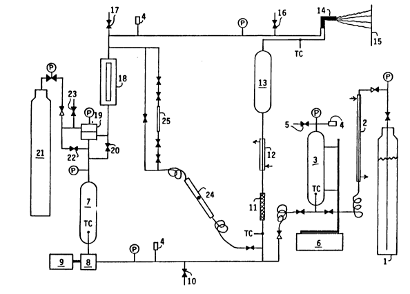
The apparatus listed in Table 2 above was
assembled as shown in the schematic representation
contained in Figure 4. Rigid connections were made
with Dekuron 1/4-inch diameter, .036-inch thick,
seamless, welded, type 304 stainless steel hydraulic
tubing ASTM A-269 with 5000-psi pressure rating,
using SwagelokTM fittings. The pressure tank (17)
was connected to the pump (8) using a Graco 3/8-inch
static-free nylon high-pressure hose model #061-221
with 3000-psi pressure rating. All other flexible
connections were made using Graco 1/4-inch
static-free nylon high-pressure hoses model #061-214
with 5000-psi pressure rating.
The coating concentrate and carbon dioxide
were pumped and proportioned by using a Graco
Variable Ratio Hydra-CatTM Proportioning Pump unit
(9). It proportions two fluids together at a given J
volume ratio by using two piston pumps (7 and 8)
D-15,997
_ 43 _ 1336662
that are slaved together. The piston rods for each
pump are attached to opposite ends of a shaft that
pivots up and down on a center fulcrum. The volume
ratio is varied by sliding pump (7) along the shaft,
which changes the stroke length. The pumps are
driven on demand by an air motor (10). Pumping
pressure is controlled by the air pressure that
drives the air motor. The pumps are double-acting;
they pump on upstroke and downstroke. The primary
pump (8) was used to pump the coating concentrate.
It was of standard design, having one inlet and one
outlet. It fills through a check valve at the
bottom and discharges through a check valve at the
top. A third check valve is located in the piston
head, which allows liquid to flow from the bottom
compartment to the top compartment when the piston
is moving downward. This type of pump is designed
to be used with low feed pressure, typically below
100 psi. The coating concentrate was supplied to
the primary pump (8) from a two-gallon pressure tank
(17). After being pressurized in the pump to spray
pressure, the solution was then heated in an
electric heater (20) to reduce its viscosity (to aid
mixing with carbon dioxide), filtered in a fluid
filter (21) to remove particulates, and fed through
a check valve (22) into the mix point with carbon
dioxide. The secondary pump (7) on the
proportioning pump unit (9) was used to pump the
liquid carbon dioxide. A double-acting piston pump
(7) with a four-check-valve design was used because
of the high vapor pressure of carbon dioxide. The
pump has an inlet and an outlet on each side of the
~-15,997
- 44 - 1 336662
piston; no flow occurs through the piston. The
proportion of carbon dioxide pumped into the spray
solution is varied by moving the secondary pump (7)
along the moving shaft. The carbon dioxide pump was
positioned to give 46% of maximum piston
displacement. The carbon dioxide feed line and
circulation loop were filled with carbon dioxide and
vented through valve (34) several times to purge air
from the system. Then the valves to the mixing
point were closed and the carbon dioxide feed line
was filled to prime pump (7). The liguid carbon
dioxide was pumped from Hoke cylinder (3), which was
filled from cylinder (1) by venting (5) gaseous
carbon dioxide. The cylinder was pressurized with
nitrogen (5) to a pressure of 1050 psig to prevent
cavitation in the carbon dioxide pump. The cylinder
(3) was mounted on a 16-kilogram Sartorius
electronic scale with 0.1-gram sensitivity so that
the uptake of carbon dioxide could be measured.
After being pressurized to spray pressure in pump
(7), the liguid carbon dioxide was fed unheated
through check valve (23) to the mix point with the
coating concentrate. After the coating concentrate
and carbon dioxide were proportioned together at the
mix point, the mixture was mixed in static mixer
(24) and pumped on demand into a circulation loop,
which circulates the mixture at spray pressure and
temperature to the spray gun (30). The mixture was
heated in an electric heater (25) to obtain the
desired spray temperature and filtered in a fluid
filter (26) to remove particulates. Fluid pressure
regulator (28) was installed to lower the spray
D-15,997
1 336662
- 45 -
pressure below the pump pressure, if desired, or to
help maintain a constant spray pressure. A Jerguson
site glass (29) was used to examine the phase
condition of the mixture. Circulation flow in the
circulation loop was obtained through the use of
gear pump (32).
A clear acrylic coating concentrate having
a total weight of 7430 grams was prepared by mixing
the following materials:
4830 grams of Rohm ~ Haas AcryloidTM
AT-400 Resin, which contains 75%
nonvolatile acrylic polymer dissolved in
25% methyl amyl ketone solvent,
1510 grams of American Cyanamid
CymelTM 323 Resin, which is a
cross-linking agent that contains 80%
nonvolatile melamine polymer dissolved in
20% isobutanol solvent,
742 grams of methyl amyl ketone
solvent,
348 grams of n-butanol solvent.
The coating concentrate contained 65.0% nonvolatile
polymer solids and 35.0% volatile organic solvent.
The pressure tank (17) was filled with the
concentrate and pressurized with air to 50 psig.
The coating concentrate primary pump (8) was primed
by opening a drain valve on the bottom of filter
(21) until air was purged from the line.
The air pressure regulator (13) was
adjusted to supply the air motor (10) with air at a
pressure of 67 psig to pressurize the feed lines.
The valves to the mix point were opened and the
D-15,997
-
- 46 - 1 336662
circulation loop filled with material. With the
circulation loop return valve closed, to give plug
flow around the circulation loop with no backmixing,
material was drained from valve (34) until a uniform
composition was obtained. The coating concentrate
heater (20) was adjusted to give a feed temperature
of 40 C. The circulation heater (25) was adjusted
to give the spray temperature. The circulation loop
return valve was opened and the spray mixture was
circulated at a high rate by adjusting the gear pump
(32) to a rate of 35 revolutions per minute.
The spray gun (30) was a Graco
electrostatic airless hand spray gun model AL4000
with circulating adapter #208-433 and 2000-psig
maximum working pressure. The spray tip was
#270-411, which has a .011-inch orifice diameter and
a fan width rating of 8-10 inches at a distance of
twelve inches. The spray was charged by a single
external electrode, which was a short wire
positioned about 7 millimeters in front of the
orifice from an extension of the spray tip. The
wire electrode was perpendicular to the plane of the
spray and extended to about 2 millimeters from the
centerline of the spray. The spray gun housing and
spray tip housing were made of electrically
insulating materials. The power supply was a Graco
75-kilovolt power supply model PS7500 with a
high-voltage cable and a switch cable attached to
the spray gun. The power supply, spray gun, panel,
and other equipment were electrically grounded.
The liquid spray mixture contained
approximately 47% nonvolatile polymer solids, 25%
~-15,997
- 47 - 1 336662
volatile organic solvent, and 28~ carbon dioxide.
The spray pressure was 1550 psig and the spray
temperature was 58 C. The spray mixture was a clear
single-phase solution. Test panels were mounted
vertically, held by a magnet attached to a grounded
vertical pole. A high electrical voltage of 60
kilovolts was applied to the external electrode on
the spray gun as two panels were sprayed. This
produced an electrostatic current of 25
microamperes. Both panels showed good wrap around
of coating deposited onto the back side of the
panels. Coating extended continuously inward from
the back edges of the panels. Thin coating was
deposited all the way to the center of the backside
of the panels. This showed that the spray was
electrically charged, that the charge was retained
by the droplets in the spray, and that the charged
droplets were electrostatically deposited onto the
panel. During the spraying, some foam grew on the
electrode, because the outside of the fan grazed it,
but this did not interfere with charging the spray.
However, droplets of foam were entrained from the
electrode into the spray and were deposited onto the
coatings. The 25-microampere current level showed
that the spray mixture with supercritical carbon
dioxide fluid was electrically insulating, so that
electrical current did not leak back to the grounded
equipment. No electrically charged mist was
observed being given off from the periphery of the
spray. Then two panels were sprayed the same way
with no applied electrical voltage, to establish
reference coatings; this showed that no coating is
D-15,997
- 1 336662
- 48 -
deposited onto the back side of the panels when the
spray is not electrostatically charged. This
demonstrated that more coating material was
deposited on the panels when the spray was
electrically charged and therefore that the transfer
efficiency was increased. The panels were baked in
an oven at a temperature of 120 C for twenty
minutes. The panels were covered by thin clear
glossy coherent polymeric coatings.
Example 2
The same apparatus and procedure were used
as in Example 1, except that refrigeration was used
to control cavitation in the carbon dioxide pump
inste,ad of pressurization with nitrogen. Liquid
carbon dioxide was pumped directly from cylinder (1)
through refrigeration heat exchanger (2) to carbon
dioxide pump (7). For measuring the carbon dioxide
uptake rate, the carbon dioxide was pumped from Hoke
cylinder (3) through heat exchanger (2) to pump
(7). The refrigeration flow was adjusted to a
temperature of -10 C and circulated through the
refrigeration heat exchanger (2) and refrigeration
tracing on pump (7). The carbon dioxide temperature
at pump (7) was -3 C. The carbon dioxide bulk
cylinder pressure was 850 psig. The carbon dioxide
pump was positioned to give 45~ of maximum piston
displacement.
A blue metallic acrylic enamel coating
concentrate was prepared by mixing the following
materials:
D-15,997
-- 1 336~6~
- 49 -
two gallons of Du Pont CentariTM Acrylic
Enamel B8292A Medium Blue Metallic Auto
Refinish Paint,
736 grams of ethyl 3-ethoxypropionate,
240 grams of butyl CELLOSOLVETM acetate,
8 pumps of Auto Fisheye eliminator.
This paint is normally reduced before usage with
thinner (Du Pont 8034S Acrylic Enamel Reducer) in
the amount of adding one gallon of thinner to two
gallons of paint. But no Acrylic Enamel Reducer was
used. Because the paint contains a large proportion
of low-boiling-point solvent, small amounts of ethyl
3-ethyoxypropionate and butyl CELLOSOLVETM acetate
were added to increase the proportion of high-
boiling-point solvent, to aid leveling of the
coating. Therefore the coating concentrate
contained three-quarters of a gallon less volatile
organic solvent than normally reduced paint.
The spray temperature was 50 C and the
spray pressure was 1600 psig. The spray mixture
contained 30.8% carbon dioxide. The carbon dioxide
was fully soluble in the paint. Test panels were
hand sprayed, flashed for a few minutes, and baked
in an oven at a temperature of 60 C for one hour.
Coating thickness was measured at nine
places (spaced as an array) on each panel by using a
magnetic coating thickness meter (Paul N. Gardner
Company, Fort Lauderdale, ~lorida). Coating gloss
was measured by using GlossgardTM II 20-Degree and
60-degree Glossmeters (Gardner/Neotec Instrument
Division, Pacific Scientific Company, Silver Spring,
Maryland), which measures the intensity of a beam of
D-15,997
- 50 - 1 ~36662
light reflected off of the coating at an angle of
twenty degrees or sixty degrees from perpendicular.
Gloss was measured at the top, center, and bottom of
each panel. Coating distinctness of image was
measured at the center of each panel by using a
Distinctness of Image Meter, Model 300 (Mechanical
Design and Engineering Company, Burton, Michigan),
which is a viewing box in which the clarity of
images reflected off of the coating and reference
surfaces are compared.
The electrostatic airless spray gun was the
same as in Example 1. The electrostatic spray tip
was Graco #271-410, which has a .010-inch orifice
diameter and a fan width rating of 8-10 inches.
First, several panels were sprayed as
references with no applied electrical voltage; this
showed that no coating is deposited onto the back
side of the panels. However, some of the spray hit
the electrode and formed foam that was entrained
into the spray and deposited onto the coating as
large drops. The coating deposition was uniform
(except for the scattered drops from the electrode),
but the metallic appearance was slightly mottled.
The coatings were bubble free. The properties of
these coatings are given below.
Spray Spray Average 20-Degree 60-Degree Distinct.
Temperature Pressure Thickness Gloss Gloss of Image
50 C 1600 psi 0.93 mil 62% 87% 60%
50 C 1600 psi 0.94 mil 61% 87% 60%
50 C 1600 psi 1.10 mil 71% 89% 65%
D-15,997
-
- 51 - I 336662
Then a high electrical voltage of 68
kilovolts was applied to the charging electrode.
This produced an electrostatic current of 28
microamperes while spraying. This showed that the
spray mixture was electrically insulating so that
charge leakage did not occur. Electrically grounded
test panels were sprayed with a high electrical
voltage of 60 kilovolts applied to the charging
electrode. Coating was deposited well onto the back
side of the panels, which showed that the droplets
were being electrically charged, were retaining
their electrical charge, and were being attracted to
the panel by electrical force. This demonstrates
that transfer efficiency was increased. As before,
some of the spray hit the electrode and formed foam,
which was entrained into the spray and was deposited
onto the coating as large drops. This did not
interfere with the charging. The coatings had the
same appearance as the reference coatings, except
that the edges were somewhat darker in color. This
showed that deposition was heavier along the edges
of the panel because of the electrostatic
attraction. The properties of these coatings are
given below.
Spray Spray Average 20-Degree 60-Degree Distinct.
Temperature Pressure Thickness Gloss Gloss of Image
S0 C 1600 psi 0.89 mil 51% 83% 55%
50 C 1600 psi 0.90 mil 58% 87% 55%
50 C 1600 psi 0.90 mil 59% 87% 60%
D-15,997
-
- 52 - 1 3 3 6 6 6 2
Example 3
The apparatus, procedure, coating
concentrate, spray mixture, electrostatic spray gun,
and spray tip were the same as in Example 2.
The spray temperature was 50 C and the
spray pressure was 1850 psig. Electrically grounded
panels were sprayed with a high electrical voltage
of 60 kilovolts applied to the charging electrode.
Coating was deposited well onto the back side of the
panels, which showed that the droplets were being
deposited electrostatically. The higher spray
pressure than in Example 2 produced a metallic paint
coating with less mottled appearance and better
metallic laydown. The higher pressure also
increased the amount of spray that hit the
electrode, but this did not interfere with the
charging. More foam was entrained into the spray
and deposited onto the coating as large drops. The
coatings had the following properties:
Spray Spray Average 20-Degree 60-Degree Distinct.
Temperature Pressure Thickness Gloss Gloss of Image
50 C 1850 psi 0.73 mil 41X 79% 50%
50 C 1850 psi 0.78 mil 35% 74% 40%
Example 4
The apparatus, procedure, coating
concentrate, spray mixture, electrostatic spray gun,
and spray tip were the same as in Example 3.
The spray temperature was 60 C and the
spray pressure was 1900 psig. Electrically grounded
panels were sprayed with a high electrical voltage
of 60 kilovolts applied to the charging electrode.
~-15,997
~r
_ 53 1336662
Coating was deposited well onto the back side of the
panels, which showed that the droplets were being
deposited electrostatically. The coatings obtained
were uniform in gloss, color, and metallic
appearance; they were not mottled as in Examples 2
and 3. However, as before, some of the spray hit
the electrode and formed foam, which was entrained
into the spray and deposited onto the coatings. The
coatings had the following properties:
Spray Spray Average 20-Degree 60-Degree Distinct.
Temperature Pressure Thlckness Gloss Gloss of Image
60 C 1900 psi 0.59 mil 35% 73% 40%
60 C 1900 psi 0.68 mil 41% 79% 45%
60 C 1900 psi 0.77 mil 48% 83% 45%
60 C 1900 psi 0.99 mil 45% 80% 45%
60 C 1900 psi 1.00 mil 49% 84% 50%
60 C 1900 psi 1.03 mil 57% 86% 55%
To prevent the spray from hitting the
electrode, the electrode was then bent farther
outward from the spray. This did not affect the
charging, because at a high electrical voltage of 67
kilovolts, the same electrostatic current of 28
microamperes was produced. No spray hit the
repositioned electrode, so no droplets of foam were
deposited onto the coatings. Good coatings were
sprayed that were uniform in gloss, color, and
metallic appearance (except for being somewhat
darker along the edges due to enhanced electrostatic
deposition). The metallic particles were properly
and uniformly laid down and oriented to reflect
light. The coatings were bubble free. All panels
showed good electrostatic wrap around of coating
D-15,997
- 54 - 1 336~
deposited onto the back side of the panels. Coating
gloss and distinctness of image increased with
coating thickness. The coatings had the following
average properties:
Spray Spray Average 20-Degree 60-Degree Distinct.
Temperature Pressure Thickness Gloss Gloss of Ima~e
60 C 1900 psi 0.58 mil 36% 74% 40%
60 C 1900 psi 0.61 mil 30% 70% 40%
60 C 1900 psi 0.69 mil 40% 78% 40%
60 C 1900 psi 0.72 mil 40% 79% 45%
60 C 1900 psi 0.73 mil 39% 78% 4~%
60 C 1900 psi 0.82 mil 47% 82% 55%
60 C 1900 psi 0.94 mil 50% 84% 55%
60 C 1900 psi 0.~4 mil 52% 84% 55%
For comparison, paint reduced with thinner
was prepared by adding Du Pont 8034S Acrylic Enamel
Reducer to the Du Pont CentariTM Metallic Paint in
the proportion of one gallon of thinner to two
gallons of paint. Test panels were sprayed by using
a conventional air spray gun. The properties of the
coatings are given below. The metallic appearance
of the coatings sprayed with supercritical carbon
dioxide fluid was more uniform than that of the air
sprayed coatings.
Average 20-Degree 60-Degree Distinct.
Thickness Gloss Gloss of Image
0.89 mil 64% 88% 65%
1.19 mil 68% 88% 60%
Example 5
The apparatus, procedure, coating
concentrate, spray mixture, electrostatic spray gun,
D-15,997
- 55 - 1336662
and spray tip were the same as in Example 4. The
electrode was repositioned as in Example 4 to
prevent spray from hitting it.
The spray temperature was 60 C and the
spray pressure was 1900 psig. An unused empty
one-gallon metal paint can was mounted on the
grounded panel holder with its axis horizontal and
with the open end pointed towards the spray gun. As
a reference, the can was sprayed with no applied
electrical voltage. The spray gun was kept parallel
to the axis of the can. The can was sprayed from a
distance of 10 to 12 inches. Paint was deposited
only on the rim of the can. No paint was deposited
on the sides or back of the can.
Then another can was mounted and sprayed in
the same manner, but with a high electrical voltage
of 67 kilovolts applied to the charging electrode.
The electrostatic current was 28 microamperes. The
electrostatic deposition caused paint to completely
coat the outside of the can and to be deposited
around onto the back end of the can. The
electrostatic deposition also coated the inside
walls of the can and paint was deposited on the
inside end of the can. This demonstrates the
throwing power and the electrostatic wrap around of
the electrostatic airless spray created with
supercritical carbon dioxide fluid. Several more
cans were sprayed in the same manner with the same
results. The paint deposited on the sides of the
cans had the same appearance as the coatings sprayed
onto the test panels, except that the coating
thickness decreased as the distance from the spray
increased. No coating material struck the electrode.
D-15,997