Language selection

Search

Patent 1336875 Summary

Third-party information liability

Some of the information on this Web page has been provided by external sources. The Government of Canada is not responsible for the accuracy, reliability or currency of the information supplied by external sources. Users wishing to rely upon this information should consult directly with the source of the information. Content provided by external sources is not subject to official languages, privacy and accessibility requirements.

Claims and Abstract availability

Any discrepancies in the text and image of the Claims and Abstract are due to differing posting times. Text of the Claims and Abstract are posted:

  • At the time the application is open to public inspection;
  • At the time of issue of the patent (grant).
(12) Patent: (11) CA 1336875
(21) Application Number: 613632
(54) English Title: LOW EMISSION DUAL FUEL ENGINE AND METHOD OF OPERATING SAME
(54) French Title: MOTEUR A DEUX CARBURANTS PEU POLLUANT ET SON MODE DE FONCTIONNEMENT
Status: Expired
Bibliographic Data
(52) Canadian Patent Classification (CPC):
  • 123/96
(51) International Patent Classification (IPC):
  • F02B 3/00 (2006.01)
  • F02B 7/06 (2006.01)
  • F02D 19/10 (2006.01)
  • F02B 3/06 (2006.01)
(72) Inventors :
  • HELMICH, MELVIN JOHN (United States of America)
(73) Owners :
  • AVL LIST GMBH (Austria)
(71) Applicants :
(74) Agent: DEETH WILLIAMS WALL LLP
(74) Associate agent:
(45) Issued: 1995-09-05
(22) Filed Date: 1989-09-27
Availability of licence: N/A
(25) Language of filing: English

Patent Cooperation Treaty (PCT): No

(30) Application Priority Data:
Application No. Country/Territory Date
336,789 United States of America 1989-04-12

Abstracts

English Abstract


A dual fuel engine system and method of operating the engine reduces emission rates
of pollutants. The dual fuel engine includes a fuel oil supply connected to the engine
and a fuel gas supply connected to the engine. Means connected between the fuel oil
supply and the engine inject low levels of diesel fuel into the engine. In particular, the
injection of diesel fuel is limited to pilot injection quantities only. The exhaust emission
of NOx is maintained at less than 1GM/HP-HR, where natural gas is used as the
primary fuel, and less than 0.5 GM/HP-HR where digester gas is used as the primary
fuel.


Claims

Note: Claims are shown in the official language in which they were submitted.

THE EMBODIMENTS OF THE INVENTION ID WHICH AN EXCLUSIVE
PROPERTY OF PRIVILEGE IS CLAIMED ARE DEFINED AS FOLLOWS:

1. A low emission dual fuel engine system comprising:
a dual fuel engine having a combustion chamber;
a fuel oil supply connected to said engine;
a fuel gas supply connected to said engine; and
means connected between said fuel oil supply and said
engine for injecting fuel oil into said engine, said means
connected between said engine and fuel oil supply limiting the
injection of fuel oil to the combustion chamber to pilot
ignition quantities only, wherein said limiting means includes
means for limiting the injection of fuel oil such that the
exhaust emission of NOx is at an emission rate of less then 1
GM/HP-HR, whereby the exhaust emission performance of the dual
fuel engine is enhanced.


2. The dual fuel engine system of claim 1 wherein said
fuel oil is diesel fuel.


3. The dual fuel engine system of claim 1 wherein said
fuel gas is natural gas.


4. The dual fuel engine system of claim 1 wherein said
limiting means limits the injection of fuel oil such that the
exhaust emission of NOx is at an emission rate two less then
0.5 GM/HP-HR.


5. The dual fuel engine system of claim 4 wherein said
fuel gas is digester gas.


6. The dual fuel engine system of claim 1 wherein said
means connect between said fuel oil supply and said engine
comprises a fuel injection pump connected by a high-pressure
line to a fuel injection nozzle.


7. The dual fuel engine system of claim 6 wherein said
fuel injection nozzle comprises an annular nozzle spray tip,
said tip having four orifices for the passage there through of
fuel oil, each of said orifices having a diameter of about
0.0157 in., said orifices being disposed at a spray angle of
120° with respect to the longitudinal axis of said fuel
injection nozzle.


8. The dual fuel engine system of claim 6 wherein said
fuel injection nozzle comprises an annular nozzle spray tip,
said tip having six orifices having a diameter of about 0.0106
in., said orifices being disposed at a spray angle of 120° with
respect to the longitudinal axis of said fuel injection nozzle.


9. The dual fuel engine system of claim 8 wherein said
fuel injection pump connected between said fuel oil supply and
said engine comprises an automatic type fuel pump and said fuel
injection nozzle comprises a pencil type fuel injection nozzle.


10. The dual fuel engine system of claim 6 wherein said
fuel injection nozzle comprises an annular nozzle spray tip,
said tip having seven orifices having a diameter of about
0.0177 in., said orifices being disposed at a spray angle of
about 140° with respect to the longitudinal axis of said fuel
injection nozzle.


11. The dual fuel engine system of claim 6 wherein said
fuel gas supply connected to said engine by means of a fuel
induct system.


12. The dual fuel engine system of claim 11 wherein said
fuel injection system comprises an air inlet valve
concentrically disposed relative to a gas inlet valve, said
valve being commonly operable so as to mix air and gaseous fuel
supplied to said engine.


13. The dual fuel engine system of claim 11 further
comprising turbo charger means connected to said induction
system for supplying of compressed air to said air inlet valve.


14. A method of operating a dual fuel engine comprising:


injecting fuel oil to said engine;
supplying fuel gas to said engine;
limiting the injection of fuel oil to said engine to


pilot ignition quantities wherein an exhaust emission of NOx is
limited to an emission rate of less than 1 GM/HP-HR, whereby
the exhaust emission performance of the dual fuel engine is
enhanced.

15. The method of claim 14 wherein said fuel gas is
natural gas.


16. The method of claim 14 wherein said fuel gas is
digester gas.


17. A combustion system for a dual fuel engine comprising:


an engine;
a fuel oil supply for said engine;
a fuel gas supply for said engine; and
means connected between said fuel oil supply and said
engine for injection fuel into said engine, said means
connected between said engine and said fuel oil supply limiting
the injection of fuel oil to pilot ignition quantities only,


wherein said limiting means includes means for limiting the
injection of fuel oil such that the exhaust emission of NOx is
that an emission rate of less than 1 GM/HP-HR whereby the
exhaust emission performance of the dual fuel engine is
enhanced.


18. The combustion system of claim 17 wherein said fuel
oil is diesel fuel.


19. The combustion system of claim 17 wherein said fuel
gas is natural gas.


20. The combustion system of claim 17 wherein said
limiting means limits the exhaust emission of NOx to an
emission rate of less than 0.5 GM/HP-HR.


21. The combustion system of claim 20 wherein said fuel
gas is digester gas.


22. The combustion system of claim 17 wherein said means
connected between said fuel oil supply and said engine
comprises a fuel injection pump connected by a high-pressure
line to a fuel injection nozzle.


23. The combustion system of claim 22 wherein said fuel
injection nozzle comprises an annular nozzle spray tip, said


tip having four orifices for the passage there through of fuel
oil, each of said orifices having a diameter of about 0.0157
in., said orifices being disposed at a spray angle of 120° with
respect to the longitudinal asis of said fuel injection nozzle.


24. The combustion system of claim 22 wherein said fuel
injection nozzle comprises an annular nozzle spray tip, said
tip having six orifices having a diameter of about 0.0106 in.,
said orifices being disposed at a spray angle of 120° with
respect to the longitudinal axis of said fuel injection nozzle.


25. The combustion system of claim 24 wherein said fuel
injection pump connected between said fuel supply and said
engine comprises automatic type fuel pump and said fuel
injection nozzle comprises a pencil type fuel injection nozzle.


26. The combustion system of claim 22 wherein said fuel
injectio nozzle comprises an annular nozzle spray tip, said tip
having seven orifices having a diameter of about 0.0177 in.,
said orifices being disposed at a spray angle of 140° with
respect to the longitudinal axis of said fuel injection nozzle.


Description

Note: Descriptions are shown in the official language in which they were submitted.


- t 336875

LOW EMISSION DUAL ~u~L ENGINE AND METHOD OF OPERATING SAME


The present invention relates to dual fuel engine
systems, and more particularly to low gaseous exhaust emission
dual fuel engine systems and a method of operating a dual fuel
engine system.


Dual fuel engines are well-known in the art, as
evidence by U.S. Patent Nos. 4,603,674 to Tanaka; 4,463,734 to
Akeroyd; and 4,527,516 to Foster. Conventional dual fuel
engines are built to operate on the Otto cycle and employ
compression ignition of an oil charge to burn a gaseous main
fuel energy charge. The quantity of diesel oil injected in the
pilot charge is normally 4 to 7 percent of the energy required
for full load operation of the engine. In the case of the
typical dual fuel engine, the diesel fuel injection system is
designed so that full load operation can be achieved with
diesel fuel oil delivery only, i.e., with no gaseous fuel added
to the fuel charge.


Control of engine emissions, particularly NOx
emissions, has become a concern in recent years, as evidenced
by U.S. Patent No. 4,306,526 to Schaub et al, of which the
present inventor is co-inventor, and U.S. Patent No. 4,524,730
to Doell et al.


However, no dual fuel engine system to date has
achieved a low emission rate of pollutants, particularly


- 1 336875
-


NOx levels, which is acceptable in certain parts of the United
States and Europe.


This invention provides a low emission dual fuel
engine system comprising a dual fuel engine having a combustion
chamber, a fuel oil supply connected to the engine, a fuel gas
supply connected to the engine, and means connected between the
fuel oil supply and the engine for injecting fuel oil into the
engine, and for limiting the injection of fuel oil to the
combustion chamber to pilot ignition quantities only. The
limiting means includes means for limiting the injection of
fuel oil such that the exhaust emission of NOx is at an
emission rate of less than 1 GM/HP-HR, whereby the exhaust
emission performance of the dual fuel engine is enhanced.


In another aspect, this invention also provides a
method of operating a dual fuel engine comprising injecting
fuel oil to the engine, supplying fuel gas to the engine, and
limiting the injection of fuel oil to the engine to pilot
ignition quantities where an exhaust emission of NOx is limited
to an emission of less than 1 GM/HP-HR, whereby the exhaust
emission performance of the fuel engine is enhanced.


In yet another aspect, the invention provides a
combustion system for a dual fuel engine comprising an engine,
a fuel oil supply for the engine, a fuel gas supply for the
engine, and means connected between the fuel oil supply and the


- lA -


. ..

1 336875
engine for injection fuel into the engine. The means connected
between the engine and the fuel oil supply limits the injection
of fuel oil to pilot ignition quantities only. The limiting
means includes means for limiting the injection of fuel oil
such that the exhaust emission of NOx, is that an emission rate
of less than 1 GMVHP-HR whereby the exhaust emission
performance of the dual fuel engine is enhanced.


In view of the foregoing limitations and shortcomings
of the prior art systems, as well as other disadvantages not
specifically mentioned above, it is apparent


- lB -

6811b/9-11
~t'~
...,., ~ .. .....

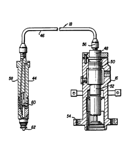
Representative Drawing
A single figure which represents the drawing illustrating the invention.
Administrative Status

For a clearer understanding of the status of the application/patent presented on this page, the site Disclaimer , as well as the definitions for Patent , Administrative Status , Maintenance Fee  and Payment History  should be consulted.

Administrative Status

Title Date
Forecasted Issue Date 1995-09-05
(22) Filed 1989-09-27
(45) Issued 1995-09-05
Expired 2012-09-05

Abandonment History

There is no abandonment history.

Payment History

Fee Type Anniversary Year Due Date Amount Paid Paid Date
Application Fee $0.00 1989-09-27
Registration of a document - section 124 $0.00 1990-04-06
Maintenance Fee - Patent - Old Act 2 1997-09-05 $100.00 1997-08-13
Maintenance Fee - Patent - Old Act 3 1998-09-08 $100.00 1998-08-04
Registration of a document - section 124 $0.00 1999-04-22
Maintenance Fee - Patent - Old Act 4 1999-09-06 $100.00 1999-08-09
Maintenance Fee - Patent - Old Act 5 2000-09-05 $150.00 2000-08-08
Maintenance Fee - Patent - Old Act 6 2001-09-05 $150.00 2001-08-07
Maintenance Fee - Patent - Old Act 7 2002-09-05 $150.00 2002-08-08
Registration of a document - section 124 $100.00 2002-11-26
Maintenance Fee - Patent - Old Act 8 2003-09-05 $150.00 2003-08-05
Maintenance Fee - Patent - Old Act 9 2004-09-07 $200.00 2004-08-09
Maintenance Fee - Patent - Old Act 10 2005-09-06 $250.00 2005-08-24
Maintenance Fee - Patent - Old Act 11 2006-09-05 $250.00 2006-07-26
Maintenance Fee - Patent - Old Act 12 2007-09-05 $250.00 2007-08-29
Maintenance Fee - Patent - Old Act 13 2008-09-05 $250.00 2008-08-21
Maintenance Fee - Patent - Old Act 14 2009-09-08 $250.00 2009-08-31
Maintenance Fee - Patent - Old Act 15 2010-09-07 $450.00 2010-08-26
Maintenance Fee - Patent - Old Act 16 2011-09-06 $450.00 2011-08-31
Owners on Record

Note: Records showing the ownership history in alphabetical order.

Current Owners on Record
AVL LIST GMBH
Past Owners on Record
COOPER CAMERON CORPORATION
COOPER INDUSTRIES, INC.
HELMICH, MELVIN JOHN
Past Owners that do not appear in the "Owners on Record" listing will appear in other documentation within the application.
Documents

To view selected files, please enter reCAPTCHA code :


To view images, click a link in the Document Description column. To download the documents, select one or more checkboxes in the first column and then click the "Download Selected in PDF format (Zip Archive)" or the "Download Selected as Single PDF" button.

List of published and non-published patent-specific documents on the CPD .

If you have any difficulty accessing content, you can call the Client Service Centre at 1-866-997-1936 or send them an e-mail at CIPO Client Service Centre.


Document
Description 
Date
(yyyy-mm-dd) 
Number of pages   Size of Image (KB) 
Prosecution Correspondence 1990-01-30 1 38
Prosecution Correspondence 1992-05-08 3 61
Prosecution Correspondence 1992-05-11 112 7,659
Prosecution Correspondence 1992-12-17 26 4,130
Prosecution Correspondence 1995-03-21 1 31
PCT Correspondence 1995-06-21 1 39
PCT Correspondence 1990-01-30 1 32
Examiner Requisition 1992-02-03 1 61
Examiner Requisition 1990-03-21 1 14
Office Letter 1990-01-12 1 33
Representative Drawing 2002-03-06 1 9
Cover Page 1995-09-05 1 18
Abstract 1995-09-05 1 15
Description 1995-09-05 3 86
Claims 1995-09-05 6 174
Drawings 1995-09-05 2 70
Correspondence 2004-09-21 1 1
Correspondence 2002-08-16 1 14
Correspondence 2003-09-25 1 12
Fees 2003-09-04 1 39
Fees 2004-08-31 1 33
Fees 2004-08-31 3 113
Fees 2005-08-24 1 33
Fees 2006-07-26 1 32
Fees 2011-08-31 1 38
Fees 2007-08-29 1 35
Fees 2008-08-21 1 35
Fees 2009-08-31 1 38
Fees 2010-08-26 1 42