Language selection

Search

Patent 1337027 Summary

Third-party information liability

Some of the information on this Web page has been provided by external sources. The Government of Canada is not responsible for the accuracy, reliability or currency of the information supplied by external sources. Users wishing to rely upon this information should consult directly with the source of the information. Content provided by external sources is not subject to official languages, privacy and accessibility requirements.

Claims and Abstract availability

Any discrepancies in the text and image of the Claims and Abstract are due to differing posting times. Text of the Claims and Abstract are posted:

  • At the time the application is open to public inspection;
  • At the time of issue of the patent (grant).
(12) Patent: (11) CA 1337027
(21) Application Number: 469304
(54) English Title: RAILWAY HIGHWAY VEHICLE
(54) French Title: VEHICULE DE TRANSPORT ROUTIER ET FERROVIAIRE
Status: Expired
Bibliographic Data
(52) Canadian Patent Classification (CPC):
  • 104/33
(51) International Patent Classification (IPC):
  • B60F 1/04 (2006.01)
  • B61D 3/10 (2006.01)
  • B61D 3/12 (2006.01)
  • B61D 3/18 (2006.01)
  • B61D 47/00 (2006.01)
  • B61G 5/02 (2006.01)
(72) Inventors :
  • WICKS, HARRY O. (United States of America)
(73) Owners :
  • WABASH NATIONAL, L.P. (United States of America)
(71) Applicants :
  • WICKS, HARRY O. (United States of America)
(74) Agent: OSLER, HOSKIN & HARCOURT LLP
(74) Associate agent:
(45) Issued: 1995-09-19
(22) Filed Date: 1984-12-04
Availability of licence: N/A
(25) Language of filing: English

Patent Cooperation Treaty (PCT): No

(30) Application Priority Data: None

Abstracts

English Abstract


A railway train of truck trailers or trailer
chassis coupled end to end with the back end of each
trailer (and the front end of a following trailer,
if any) pivotally supported on the bolster of a
railway truck by a subframe having vertically facing
load carrying parts engaged by mating parts on the
back end of the leading trailer on opposite sides
of its centerline. The following trailer is supported
by structure pivotally supported by said subframe.
When connected in the railway mode, the road wheels
of the trailer are supported clear of the tracks.


Claims

Note: Claims are shown in the official language in which they were submitted.


THE EMBODIMENTS OF THE INVENTION IN WHICH AN EXCLUSIVE
PROPERTY OR PRIVILEGE IS CLAIMED ARE DEFINED AS FOLLOWS:
1. A railway train comprising one or more end to end
trailer vehicles each having its highway engaging wheels
supported above a railway track, a railway truck having railway
wheels on the track and a bolster with a load carrying thrust
bearing, an adapter frame supported by said bearing for rotation
about a vertical axis and having laterally spaced horizontal load
carrying forks on opposite sides of the centerline of one of said
trailers receivable in sockets provided and in load carrying
relation to one end of said one of said trailers.
2. The structure of claim 1 in which the truck carries its
own brakes.
3. The structure of claim 1 in which the forks are latched
to said one trailer.
4. The structure of claim 1 in which the adapter frame has
side sway limiting stops for the end of the trailer adjacent said
one trailer.
5. The structure of claim 1 in which pivoting of said one
trailer about a vertical axis is effected by pivoting of the
adapter frame on said thrust bearing.
6. The structure of claim 1 in which the railway wheels
are mounted in a frame and the bolster is resiliently supported
by the frame.
7. The structure of claim 6 in which the brakes for the
truck are carried by the frame.
8. The structure of claim 1 in which said forks are
received in sockets at the back end of said one of said trailers.
9. The structure of claim 8 in which said sockets are in
the rear sill of said one of said trailers.
10. The railway train comprising one or more trailer
vehicles each having at its front end a fifth wheel coupling
means adapted to couple with a fifth wheel coupling means of a
highway tractor and at its back end rear wheels to support the
back end of said vehicle while moving along a highway, a railway

11


truck having railway wheels and a bolster with a load carrying
vertical thrust bearing, an adapter frame rotatably supported by
said bearing and having laterally spaced horizontal load carrying
forks received in load carrying relation to the back end of one
of said road trailers, a load carrying tongue on the front end
of another trailer received in a socket member on the back end
of said one trailer, said socket member being between said forks
and in load carrying relation to said tongue, and a pin coaxial
with said bearing and carried by said socket member and extending
through said tongue to establish a push and pull draft connection
between the tongue and said socket member, said bearing and pin
being on a vertical axis between said forks.
11. The structure of claim 1 in which the highway wheels
are vertically retractable for railway operation.
12. A railway train comprising one or more end to end
highway trailer vehicles, each having its highway engaging wheels
supported above a railway track, a railway truck having railway
wheels on said track and a bolster with a load carrying thrust
bearing, and a rigid adapter frame supported by said thrust
bearing for rotation about a vertical axis, said frame having a
first coupling means laterally spaced on opposite sides of the
centerline of one of said trailers made up with complementary
coupling means in the back end of said one of said trailers, said
first coupling means and said complementary coupling means being
cooperable to releasably fix said frame to said back end of said
one of said trailers and positively prevent rotation of said back
end of said one trailer relative to said frame while said frame
rotates about said vertical axis.
13. The structure of claim 12 in which said complementary
coupling means are made up with said first coupling means alter-
natively by lowering said back end of said one trailer onto said
first coupling means or by backing said one end of said one
trailer onto said first coupling means to permit making the
coupling connection at locations where trailer lifting equipment
is not available.
12


14. The structure of claim 12 in which the complementary
coupling means has laterally spaced vertical planar surfaces
engaging parallel laterally spaced vertical planar surfaces on
said first coupling means.
15. The structure of claim 12 in which the complementary
coupling means comprises an inverted channel.
16. The structure of claim 12 in which the first coupling
means is stopped against an end sill of one of said trailers and
the complementary coupling has flanges outstanding from said sill
and pinned to the flange of said first coupling means.
17. The structure of claim 12 in which the first coupling
means is made up with an inverted channel in the back end sill
of said one of said trailers.
18. A railway train comprising a plurality of end to end
highway trailer vehicles, each having its highway engaging wheels
supported above a railway track, a railway truck having railway
wheels on said track and a bolster with a load carrying thrust
bearing, and a frame supported by said bearing for rotation about
a vertical axis, said frame having a first load carrying coupling
engaged with second complementary load carrying coupling on the
centerline of one of said trailers, said couplings each having
laterally spaced vertically extending longitudinal sides, the
sides of one coupling being in telescoping relation to the sides
of the other coupling, and horizontal latch pins extending
through the sides of the couplings for holding the couplings
coupled.
19. The structure of claim 18 in which the first and second
couplings are pinned together by retractable horizontal pins.
20. The railway train comprising one or more end to end
highway trailer vehicles each having its highway engaging wheels
supported above a railway track, a railway truck having railway
wheels on the track and a bolster with a load carrying thrust
bearing, an adapter frame supported by said bearing for rotation
about a vertical axis, said trailer having at its front end a
front sill, a load carrying arm on said adapter frame stopped

13


against said sill, said sill and said arm having on opposite
sides of the centerline of the trailer laterally spaced inter-
engaging flanges and retractable pins extending through said
flanges for releasably locking said arm to said sill.
21. The structure of claim 12 in which a ball bearing is
pinned to the upper end of the frame on said vertical axis, and
an arm fixed to the front end of the trailer following said one
trailer is pivoted on said ball.
22. A combination comprising:
a railway truck having railway wheels supportable on a track
and a bolster with a load carrying thrust bearing;
frame means supported by said thrust bearing for rotation
thereon about a vertical axis;
the frame means including first coupling means having a pair
of substantially vertical sidewalls and an upwardly facing sub-
stantially horizontal surface located above the thrust bearing;
a highway trailer vehicle having highway engaging wheels
supportable above a railway track;
complementary coupling means located beneath and fixably
connected to a rear end portion of the trailer vehicle;
the complementary coupling means including a pair of
substantially vertical sidewalls and a downwardly facing
substantially horizontal surface; and
means for releasably connecting the first coupling means to
the complementary coupling means, whereby the first coupling
means may substantially mate with the second coupling means to
releasably fix the highway trailer to said frame means with the
sidewalls of the first coupling means being in substantially
side-by-side position with the sidewalls of the second coupling
means, and with the downwardly facing horizontal surface of the
complementary coupling means being on top of the upwardly facing
substantially horizontal surface of the first coupling means in
load bearing contact.
23. A combination according to claim 22, in which:
the complementary coupling means has opposing substantially


.
14


vertical sidewalls and a downwardly facing substantially horizon-
tal surface;
the first coupling means substantially mates with the
complementary coupling means to position said frame means to said
back end of said trailer; and
the mating of the first coupling means to the complementary
coupling means places a vertical sidewall of each coupling means
in substantially side-by-side position with each other.
24. A combination according to claim 22 in which when the
first coupling means and the complementary coupling means are in
substantially mating position, positive rotation about a vertical
axis is prevented between the trailer and the frame means while
the frame means rotates on the thrust bearing about said vertical
axis.
25. A combination according to claim 22 in which the said
horizontal surfaces are wider than the thrust bearing.
26. A combination according to claim 22 in which the means
for releasably connecting and disconnecting the first coupling
means to and from the complementary coupling means includes pin
means which extends through the mating sidewalls.
27. A combination according to claim 22 in which the
horizontal surface of the first coupling means includes a
forwardly and downwardly extending end portion acting as a
guidance ramp.
28. The combination of a railway truck assembly and a dual-
mode rail-highway trailer, said combination comprising:
a trailer capable of being pulled over the highway by a
truck tractor and capable of being made into a train consist for
movement over the rails, said trailer including
a body,
a plurality of highway wheels carried by the body,
a forwardly extending load bearing tongue secured at its
rear end to a forward portion of the body,
first receiving means provided in the rear end of the body
for the reception of the forward end of a tongue of a following


trailer, and
second receiving means carried by a rear portion of the
body;
a rail truck assembly including
a railway truck provided with a transversely extending
bolster provided with a centerplate bowl, and
an adapter supported on the centerplate bowl for rotational
movement about a generally vertically extending axis, the adapter
including a coupling portion received within the second receiving
means of the trailer; and
fastener means securing said coupling portion to the second
receiving means.
29. A train comprising:
a plurality of dual mode trailers, each including
a body,
highway wheel assemblies connected to the body,
a forwardly extending load bearing tongue secured at its
rear end to a forward portion of the body,
first receiving means provided in the rear of the body, and
second receiving means carried by a rear portion of the
body;
a plurality of railway truck assemblies equal in number to
the plurality of trailers, each railway truck assembly including
a railway truck provided with a transversely extending bols-
ter provided with a centerplate bowl or the like, and
an adapter supported on said centerplate bowl for rotational
movement about a generally vertically extending axis, the adapter
including a coupling portion disposed within the second receiving
means;
primary latch means capable of securing the coupling portion
to the second receiving means; and
secondary latch means capable of securing the forward end
of the forwardly extending tongue of a following trailer within
the first receiving means on the rear end of an adjacent leading
trailer.
16

Description

Note: Descriptions are shown in the official language in which they were submitted.


` , 1- 1337027

RAILWAY HIGHW~Y VEHICLE
In piggyback trains, the cross country travel is
by rail and the local delivery is by truck. This effects
savings of energy and of labor. However, the dead weight
of the piggyback flat cars makes up a large portion
of the total railway load. This invention eliminates
the piggyback cars and makes the highway trailers an
active part of the train, thereby decreasing the weight
to be transported by rail and still further increasing
the savings of combined railway-highway service.
For railway use, trailers are connected end to
end to form a train pulled by a locomotive. Adjacent
ends of the trailers in the train are coupled to a railway
truck. The coupling may be made by lifting the trailer
and lowering it onto the railway coupling. Alternatively,
the coupling may be made by backing the trailer into
the railway coupling. When the train is made up, each
railway truck supports the back end of a leading trailer
and the front end of a following trailer. In other
words, the front and back ends of each trailer are supported
by a different truck. Upon arriving at its destination,
each trailer is lifted off (or backed off~ its railway
coupling and is connected to a tractor for local delivery
by highway.
The trailer is a standard highway trailer except
for the modification required for the railway coupling.
This modification does not interfere with the highway
use and makes only a small addition to the weight of
the trailer.
In the drawing, Fig. 1 is a plan view of a crane
for moving railway trucks laterally from one track to

another; Fig. 2 is a side elevation of the crane s~own


...... . ...

: -: -


~ 33~027
-- 2 --in Fig. l; Fig. 3 is a perspective of the back end of a railway
highway vehicle and of the railway truck with which it is to be
coupled; Fig. 4 is a top plan view of a railway truck and of the
coupling members on the truck for connection respectively to
mating couplings on the front and back ends of adjoining railway
highway vehicles; Fig. 5 is a section on line 5-5 of Fig. 4; Fig.
6 is a section on line 6-6 of Fig. 4; Fig. 7 is a perspective of
a modification of Fig. 3; Fig. 8 is a top plan view of a modifi-
cation of Fig. 4; Fig. 9 is a section on line 9-9 of Fig. 8; Fig.
10 is a diagrammatic view of another railway train consisting of
a locomotive and a plurality of trailers; Fig. 11 is a fragmen-
tary side elevation showing the back end of a leading trailer of
the Fig. 10 train, the front end of a following trailer, and the
railway truck supporting the foregoing; Fig 12 is an isometric
view of the railway truck of the Fig. 10 train in position to be
coupled to the back end of the leading trailer; Fig. 13 is a
fragmentary section along the centerline of a leading and a
following trailer coupled together; Fig. 14 is a transverse
section through the rear sill of the coupling to the leading
trailer of Fig. 13, and Fig. 15 illustrates a procedure for
making up the Fig. 10 train of trailers.
Fig. 1 shows a train of railway highway trailers in the
process of being made up. The back end of the leading trailer
is connected to the front end 3 of the following trailer and the
adjoining ends 2,3 are supported by a railway truck. The trucks
are stored on a railway track 5 and are moved from track 5 to
track 6 on which the train is being made up by a crane 7 having
a main frame 8 with a crosswise movable carriage 9 at the upper
end of the main frame.
At the outer ends of the carriage are depending arms 10,11
at the lower ends of which are inwardly extending fingers 12,13
which are specifically designed to extend beneath the axles 14
of the railway truck 4. When in position beneath the axles 14,
the arms or the fingers 12,13 are lifted to elevate the truck


~P


1 337027
-- 3
clear of the track 5. The truck can then be moved from its
position on the track 5 to a position where it can be lowered
onto the track 6. After the truck is in position on the track
6, the carriage 9 is retracted to the position shown in full
lines in readiness to pick up another truck. The truck which has
been moved to the track 6 can then be rolled toward the trailer
1 and a coupling part 16 on the truck telescoped into a mating
part to be described at the front end 3 of trailer 1.
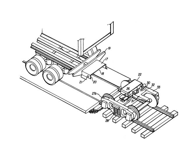
Set into the rear sill 15 of the trailer is an inverted
channel 17 open at its front end 18 and closed at its back end
by cross member 19 and having depending sides 20 which flare
outwardly at 21 to help guide rectangular coupling member 22 into
place as the trailer is lowered onto the coupling member. After
the trailer is lowered onto the coupling 22, locking pins 23 are
moved in opposite directions outwardly through registering holes
in sides 20 of the coupling member by an oppositely threaded
screw 24. When the pins 23 are in locking position, the rear
sill of the trailer is positively fixed to the coupling 22 and
the weight of


_4_ 1 3 3 7 0 2 7

the back end of the trailer is carried through center
plate thrust bearing 25 to bolster 26 of the truck.
Opposite ends of the bolster are supported by side
frames 27a and springs 28. In addition to carrying
the weight of the trailer load, the truck 4 also has
its own railway brakes. The coupling 22 forms part
of the structure which is supported by the center bearing
25. The back end of the trailer which is rigidly
connected to the coupling 22 is therefore supported
on the center bearing in the same manner as a freight
car would be supported. Side sway at the back end of
the trailer on the truck is limited by the usual stops.
At the center of the center bearing 25 is an upstand-
ing center pin 27 having at its upper end a spherical
bearing 29 for supporting the shank 30 of a coupling
member 31. The shank 30 extends out the open end of
the coupling member 22. At the back end of the shank
30 is a cross member 32 at the opposite ends of which
extend inverted channel fork members 33.
As shown in Fig. 4, the coupling 31 fits between
two lugs 34 fixed to the front sill 35 of the front
end of the following trailer. As shown in Fig. 6, the
coupling 31 has forks or prongs 33 which extend back
beneath the front end of the trailer almost to the fifth
wheel coupling pin 36 of the trailer but since the pin
36 is on the center line of the trailer and the prongs
33 are spaced on opposite sides of the center line of
the trailer, there never is any contact between the

coupling 31 and the fifth wheel pin of the trailer.


1 337027
-5-

When the coupling element 31 is in connected or coupled
position on the front end of the following trailer,
lugs 38 on the coupling are received between the lugs
34 (Fig. 4) on the front sill 35 of the trailer. The
lugs 38 project above the coupling 31 and are stopped
against the front sill 35 of the trailer (Fig. 6).
Locking pins 40, 41 carried respectively at the upper
ends of arms 42, 43 and driven in opposite directions
by oppositely threaded screw actuator 44 are extending
through aligned holes in the lugs 38 and 34 after the
coupling element 31 is properly positioned on the trailer.
Once the locking pins are in place, the front end of
the following trailer is rigidly coupled to the coupling
element 29 to allow tilting of the following trailer
in all directions. Coupling element 31 is resiliently
supported by a shear sandwich mounting 45 having one
plate 46 connected to bracket 47 fixed to coupling element
31 and its other plate 48 connected by bracket 49 to
center plate 25. The rubber body 50 sandwiched between
and bonded to plates 46 and 48 resiliently restrains
movement of the front end of the following trailer relative
to the back end of the leading trailer. The sandwich
mounting also centers the element 31 prior to coupling
to a following trailer.
In Figs. 7, 8 and 9, the coupling element 31 has
been changed by eliminating the cross member 32 and
forks 33 and substituting a flare 51 and a rectangular
box section 52. The box section 52 fits into an inverted

channel 53 set into the front sill 35 of the front end
of the following trailer. The back end of the channel
53 is closed by a cross m~mber 54a which may provide


1~337~27
--6--

a stop limiting the insertion of the box section 52
of the coupling. When the coupling is inserted in the
channel, locking pins 54, 55 carried by member 56 register
with mating openings in the adjacent side of the inverted
channel 53. Also, locking pins 57, 58 carried by member
59 come opposite or register with openings in the adjacent
side of the channel 53. An oppositely threaded drive
screw 60 cooperates with tabs 61 projecting from members
56 and 59 through the lower side of the coupling member
52 to move the locking pins in opposite directions
through the registering holes in the adjacent channels
thereby fixing the front end of the following trailer
to the shank 30 of the coupling which is pivoted on
the railway bolster by ball pivot 29. Since the channel
53 is open both at the front of the trailer and at the
bottom, it is possible to make up the coupling between
the channel 53 and the box section 52 either by backing
the trailer onto the coupling or by lifting the trailer
and dropping it in place on the coupling. The coupling
53 or 52 is resiliently supported on the center plate
25 by a shear sandwich mounting 62 having the same con-
struction and function as the sandwich mounting 45.
In the form of the invention shown in Figs. 10 -
15, the train consists of a locomotive 71, and a plurality
of trailers 72 connected end to end. When so connected,
the road wheels 73 of each trailer are supported above
the tracks or rails 74. The trailers are designed for
use in a unit train where all of the trailers have a

similar frame type or frameless type (monocoque) chassis
and coupling structure. The body styles of the trailers
may differ in accordance with shipping requirements.


_7_ 1~337027
The lead trailer in the train has at its front end a
load carrying prong 75fixed to a railway coupler 76
for coupling to the locomotive coupler 77. The trailers
in the train are standard highway trailers carried by
standard type railway trucks equipped with standard
railway type brakes. The highway trailers have add-
itional structure (to be described) to permit the
combined railway and highway use. At the front of the
trailer, the only modification necessary is the add-
ition of the prong 75.
In the use as a highway trailer, the front end i~
- _ .
carried by a fifth wheel pin 82 which is removably
locked to the fifth wheel plate of the usual truck
tractor. When used in the railway train, the gravity
load of the front end of the trailer and the braking
(buff) and draft thrusts are all-taken through the
prong 75 which is rigidly fixed to the front end of
the trailer frame. At the back end of the trailer
frame, it may be necessary to reposition the road
wheels 73 on the subframe 83 so as to have the position
shown. The purpose of the subframe 83 and the ad-
justable mounting for the road wheel is to permit
compliance with local laws relating to highway use and~or
to allow sufficient space for adaptation to the railway
mode. The particular road wheels shown are supported
by an air suspension 83a such as manufactured by Neway
or Granning so that upon release of the air pressure,
the wheels are automatically retracted well above the
rails sufficient to meet or exceed normal railroad rail

clearance requirements. The lifting means-for road
wheels in the suspension is not activated until the


-8- -1 337027
back end of the trailer is positioned so the load is
carried by a standard four wheel railway truck 84,
for example, Dresser Model DR-l; Barber Stabilized
Truck Mod. S-2-C, or equivalent.
The coupling between the truck 84 and the back
end of the leading trailer is through an àdapter
frame 85 rotatably supported on the rail truck boster
86 by its center plate (thrust bearing) 87. The
adapter frame, as shown in Fig. 3, has load carrying
fork members 88 which extend through coupling sockets
89 in the rear sill 90. The adapter frame also has
latch members 91 which extend through openings 92 in
the rear sill 90. When the forks 88 are fully received
in the sockets 89, the adapter frame is solidly latched
against the rear sill of the lead trailer by the co-
operation of the forward ends 93 of the latch members
91 with a latch bar 94.
The gravity load of the back end of the leading
trailer is carried by the forks 88 and is transferred
by the forks to the center thrust bearing 87. The
adapter frame also has sway pads 95 for limiting side
sway of the following trailer and linkage mechanism
96 for pivoting the latch members 91 clear of the latch
bar 94 and thereby releasing (or engaging) the latches
holding the adapter frame against the rear sill of the
back end of the trailer.
In the rear sill 90 there is also a socket member.
97 carrying an upwardly biased kingpin 98 which is held
in the lowered position by linkage 9~. The socket member

receives the tongue 75 of the following trailer. When
the tongue is fully received, the axis of a self aligning


-9- ~ 337027
bearing 100 in the tongue lines up with the axis of
the kingpin 98 so that upon release of the latch
mechanism 99 which has been holding the kingpin down,
the kingpin is urged upward by a spring into position
in the self aligning bearing 100 and positively couples
the back end of the leading trailer to the front end
of the following trailer. The socket 97 has enough
clearance to allow pivoting and rocking of the tongue
75 relative to the socket.
The centerline of the kingpin 98 and the axis of
bearing 87 lie on the same vertical axis. The entire
gravity load of the back end of the leading trailer
and of the front end of the following trailer is trans-
mitted from the rear sill 90 through the forks 88 to
the adapter frame and through the bearing 17 to the
bolster 16 of the railway truck 14.
Making up a train is illustrated in Fig. 15~ (l)
A trailer 102 is brought to the site by highway tractor.
(2) A railway truck 103 with its adapter frame mounted
thereon is brought from a spur 104 into loading position
on a track 105, directly behind trailer 102. (3) The
trailer 102 is backed toward the railway truck 103 until
forks 88 on the railway truck are received in sockets
89 on the trailer and latches 91 are latched over the
latch bar 94 on the trailer and the back of the trailer
lO0 is latched to the railway truck 103. The air is

then released from trailer suspension 83a and the trailer
road wheels are lifted above the track 105. The trailer
102 and truck 103 are backed as a unit into trailer
106 having its front end supported by its retractable


-lo- 1 3 3 7 0 2 7
stand or landing gear, the tongue 75 of trailer 106
being received in socket 97 in trailer 102 and the
kingpin 98 is then released to complete the coupling
of the back end of trailer 102 and the front end of
trailer 106 to the truck 103. Upon retracting the
landing gear for trailer 106 and connecting the air
brake lines to the brakes 108 for truck 103, the trailers
102 and 106 are ready for railway use.


Representative Drawing
A single figure which represents the drawing illustrating the invention.
Administrative Status

For a clearer understanding of the status of the application/patent presented on this page, the site Disclaimer , as well as the definitions for Patent , Administrative Status , Maintenance Fee  and Payment History  should be consulted.

Administrative Status

Title Date
Forecasted Issue Date 1995-09-19
(22) Filed 1984-12-04
(45) Issued 1995-09-19
Expired 2012-09-19

Abandonment History

There is no abandonment history.

Payment History

Fee Type Anniversary Year Due Date Amount Paid Paid Date
Application Fee $0.00 1984-12-04
Registration of a document - section 124 $0.00 1985-03-28
Registration of a document - section 124 $0.00 1992-03-17
Maintenance Fee - Patent - Old Act 2 1997-09-19 $100.00 1997-09-04
Maintenance Fee - Patent - Old Act 3 1998-09-21 $100.00 1998-08-19
Maintenance Fee - Patent - Old Act 4 1999-09-20 $100.00 1999-08-18
Maintenance Fee - Patent - Old Act 5 2000-09-19 $150.00 2000-08-16
Maintenance Fee - Patent - Old Act 6 2001-09-19 $150.00 2001-08-17
Maintenance Fee - Patent - Old Act 7 2002-09-19 $150.00 2002-09-16
Maintenance Fee - Patent - Old Act 8 2003-09-19 $150.00 2003-09-15
Registration of a document - section 124 $50.00 2003-10-17
Registration of a document - section 124 $100.00 2004-01-19
Maintenance Fee - Patent - Old Act 9 2004-09-20 $200.00 2004-08-19
Maintenance Fee - Patent - Old Act 10 2005-09-19 $250.00 2005-08-05
Registration of a document - section 124 $100.00 2006-02-22
Maintenance Fee - Patent - Old Act 11 2006-09-19 $250.00 2006-08-08
Maintenance Fee - Patent - Old Act 12 2007-09-19 $250.00 2007-08-08
Maintenance Fee - Patent - Old Act 13 2008-09-19 $250.00 2008-08-11
Maintenance Fee - Patent - Old Act 14 2009-09-21 $250.00 2009-09-14
Maintenance Fee - Patent - Old Act 15 2010-09-20 $450.00 2010-08-30
Maintenance Fee - Patent - Old Act 16 2011-09-19 $450.00 2011-08-30
Owners on Record

Note: Records showing the ownership history in alphabetical order.

Current Owners on Record
WABASH NATIONAL, L.P.
Past Owners on Record
RAILMASTER SYSTEM, INC.
WABASH NATIONAL CORPORATION
WICKS, HARRY O.
Past Owners that do not appear in the "Owners on Record" listing will appear in other documentation within the application.
Documents

To view selected files, please enter reCAPTCHA code :


To view images, click a link in the Document Description column. To download the documents, select one or more checkboxes in the first column and then click the "Download Selected in PDF format (Zip Archive)" or the "Download Selected as Single PDF" button.

List of published and non-published patent-specific documents on the CPD .

If you have any difficulty accessing content, you can call the Client Service Centre at 1-866-997-1936 or send them an e-mail at CIPO Client Service Centre.


Document
Description 
Date
(yyyy-mm-dd) 
Number of pages   Size of Image (KB) 
PCT Correspondence 1995-06-30 1 29
Prosecution Correspondence 1985-04-29 1 17
Prosecution Correspondence 1987-08-11 3 81
Prosecution Correspondence 1994-07-11 4 79
Examiner Requisition 1994-04-13 3 93
Examiner Requisition 1987-04-15 1 26
Representative Drawing 2000-08-10 1 31
Cover Page 1995-09-19 1 16
Abstract 1995-09-19 1 18
Description 1995-09-19 10 363
Claims 1995-09-19 6 302
Drawings 1995-09-19 13 285
Assignment 2003-10-17 4 142
Correspondence 2004-02-10 1 23
Assignment 2006-02-22 2 98