Note: Descriptions are shown in the official language in which they were submitted.
~ 338031
URETERAL STENT SYSTEM
Field of the Invention
The present invention relates generally to ureteral
stents. More particularly, it relates to an improved
ureteral stent which is less prone to migration or expulsion
from the kidney.
.
Background of the Invention
Indwelling ureteral catheter stents or drainage tubes
have been used to bypass ureteral obstructions or uretero-
vaginal fistulas and to achieve and to maintain urinarydrainage between the kidney and the bladder. In the past,
stents made of straight lengths of open end tubing have been
used for this purpose and have provided good drainage for
sustained periods of time. However, the use of such tubing
has not been completely satisfactory. For example, in some
instances, the tubing has migrated upward and in others it
has been expelled from the kidney.
Various attempts were made to produce stents which did
not have the problems which accompanied the use of such
tubing. For example, stents were designed which had a hook
at one end to prevent downward expulsion and which had a
flange at the other end to make upward migration of the
stent less likely. Another approach was to provide the body
1 33803 1
of the stent with sharply pointed barbs which were designed
to prevent both downward migration and expulsion from the
kidney. However, such barbs increased the diameter of the
stent making it more difficult to insert.
In the Finney U.S. Patent No. 4,212,304, issued July 15,
1979, and the Finney U.S. Patent No. 4,307,723, issued
December 29, 1981, ureteral stents are disclosed which are
soft silicone members which have hooks at each end and which
are surprisingly effective in preventing both upward migra-
tion and downward expulsion. In normal use the proximal
hook is placed in the lower calyx of the kidney or the renal
pelvis of the patient and the distal hook is placed in the
bladder. The stent then provides a passage for urine from
the kidney to the bladder. The Pinney stents are widely
accepted because they work well; they are well tolerated by
the patients; and they can be easily introduced both endo-
scopically and during open surgery.
In the Densow U.S. Patent No. 4,610,657, a modification
of a Finney-type stent is disclosed which has a hook at each
end, a central lumen and a reduced opening at the proximal
end. The stent can be placed in a patient using a pusher
wire or by the known over-the-wire technique. The guidewire
system disclosed for use with the Densow stent comprises two
separate guidewires. One of the wires is the pusher wire.
It is smaller in diameter than the lumen of the stent, but
has a proximal end which is larger than the reduced opening
at the proximal end. It is used to push the stent in place
when no obstructions are encountered. The other wire is
used when an obstruction is encountered. It is smaller in
diameter than both the first wire and the reduced opening in
1 338031
the stent. When an obstruction is encountered the stent and
the pu~her wire are withdrawn and the pu~her wire is
removed. The smaller diameter wire is inserted in the lumen
of the stent and the stent and wire reinserted; the leading
S end of the smaller wire is then advanced out the reduced
opening in the proximal end and maneuvered past the obstruc-
tion. The stent is then run over the wire past the
obstruction. Once the leading end of the stent is past the
obstruction, the stent is pushed into place with a stent
pusher.
In the Carter U.S. Patent No. 4,713,0~9 a guide system
is disclosed which can be used with either the Finney or
Densow type stents. The guide system is comprised of a
relatively flexible outer member with a flexible forgiving
tip and a relatively rigid movable core which fits within
the outer member. Methods of inserting stents using that
guide system are described in the Carter patent.
The Finney stent and the Densow modification are both
made entirely of relatively soft material, sucb a~ silicone
rubber, and are widely accepted because they are well tole-
rated, they do not migrate upwardly and they do not cause
patient discomfort. However, on occasion such stents may be
expelled downwardly out of the kidney. The Finney patent
suggests that the hooks could be reinforced by the incor-
poration of "plastic, fabric, metal or other suitablematerial" to make them less flexible and more resistant to
migration but the incorporation of such foreign materials
can detract from the otherwise good memory of the stent
material.
4 1 33803~
Stents have been made of stiffer less flexible
material, such as polyethylene, in efforts to reduce
expulsion of migration, but those stents have not been as
well accepted because a stent made of stiffer material can
cause bladder irritation and other patient discomfort.
It would be desirable to have a stent that had all the
advantages of the Finney and the Densow stents and which,
in addition, would have a greater resistance to being
expelled from the kidney.
Brief Summary of the Invention
It is an object of the present invention to disclose
an improved ureteral stent which resists migration and
expulsion from the kidney.
The stent of the present invention differs from the
described prior art stents in that it comprises a soft
flexible main body, and a nonreinforced hook portion
connected to the body for placement in the kidney of a
patient to reduce the likelihood of expulsion or migration
of the stent, and being stiffer than the main body and
formed from a material having a memory at body temperature
sufficient to resume a hook shape when the hook portion is
straightened with a straightening force, placed in the
kidney of the patient, and the straightening force is
removed.
The stent of the present invention is preferably made
of a material or materials having two different stiffnesses
or durometers. The durometer of the proximal hook portion
which curls into the kidney is relatively stiff, preferably
about 95 Shore A, and that of the remainder of the stent is
more flexible and soft, preferably about 50 to about 85
Shore A.
The stent of the present invention may take a variety
of forms, including, a Finney type stent with a closed
proximal end or an open proximal end. The guide system
1 33803 1
preferred for use with the stent of the present invention
is that of the Carter patent.
According to another aspect of the present invention,
there is provided an ureteral stent comprising a hook at
one end portion of the stent for placement in a kidney of
a patient and a hook at another end portion of the stent
for placement in a bladder of the patient, wherein the hook
at said one end portion is formed from a stiffer material
than the hook at said another end portion.
The above stated and other objects and advantages of
the invention will be apparent from the description which
follows:
Description of the Drawinqs
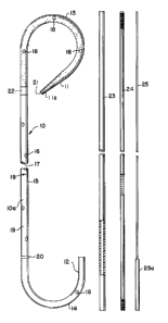
Fig. 1 is an elevational view of a kit which includes
one embodiment of a stent of the present invention and a
guide system;
Fig. 2 is an elevational view showing the stent and
guide system of Fig. 1 with the hooks of the stent
straightened;
Fig. 3 is an enlarged sectional view of the proximal
end of the stent of Fig. 2;
Fig. 4 is a view similar to Fig. 2 but showing the
unreinforced leading end of the guide system extending out
of the stent;
Fig. 5 is a partial view, in section 1, of the
unreinforcing leading end shown in Fig. 4;
Fig. 6 is an enlarged sectional view showing the
junction of the stiffer proximal hook portion and the
remainder of the stent of Fig. l;
Fig. 7 is an elevational view of another emboA;r^nt
of the stent of the present invention; and
Fig. 8 is an enlarged sectional view of the distal end
of the stent of Fig. 7.
~''
~f :i
,, .~
i-- 1 338031
Description of the Preferred Embodiment
In the preferred embodiment of the invention shown in
Fig. 1, there is seen a stent 10 which is an elongated
,. .
tubular member having a proximal end 11 and a distal end
12. Portions adjacent each of the ends 11 and 12 of the
stent 10 are formed and set in the shape of hooks 13 and
14. In the stent 10 both the proximal end 11 and the distal
end 12 as shown are open. In some cases, it may be
preferred to supply the stent 10 with the distal end 12
closed and an opening (not shown) in the side wall which is
sized to receive the guide system.
In the drawing the hook portions 13 and 14 are shown
extending in the same direction. However, the hook portions
13 and 14 preferably extend in opposite directions so that
when the stent 10 is used as an indwelling ureteral stent
the proximal end 11 can hook into the lower calyx of the
kidney or renal pelvis while the distal end 12 curves into
the bladder.
The stent 10 includes a relatively straight intermediate
section 15 which extends between the proximal hook portion
13 and the distal hook portion 14.
Referring now to Figs. 1 to 5, it can be seen that the
stent 10 has radial drainage passages 16 which connect the
lumen 17 of the stent 10 to the outside and permit inside/
outside drainage. The drainage passages 16 are preferably
spirally located about 5 centimeters apart on both sides of
the straight section 15. There are similar openings 18 in
the wall of the proximal hook portion 13. The stent 10 also
has increment markings 19 every 5 cms and an axial ring 20
which signals the physician to stop advancing the stent when
the ring reaches the ureteral orifice.
--6--
1 338031
As seen best in Figs. 3 and 5, the proximal end ll has
an externally tapered tip lla which eases the progress of
the stent lO through the ureter of the patient and assists
in the reduction of tissue trauma as the stent is advanced
through the urinary tract. The opening 21 of the tip lla is
about .041 inches so that the stent lO can be advanced over
a standard .038 inch guidewire for a standard retrograde,
over-the-wire placement.
The ureteral stent lO of the present invention differs
from the prior art stents in that the proximal hook portion
13 is made of a homogenous, thermoplastic material which is
substantially stiffer than the soft, more flexible material
from which the remainder of the stent is formed. For
example, the main body lOa of stent 10 is made of a soft
flexible material, preferably polyurethane, which has a
durometer between about 50 and about 85 Shore 'A' to which
barium sulfate has been added as the radiopaque agent. In
contrast, the proximal hook portion is made of a stiffer
less flexible material, also preferably polyurethane, having
a durometer of about 95 Shore 'A'. The higher durometer
material of the proximal hook portion 13 forms a more secure
curl into the kidney thus further minimizing migration or
explusion.
The hook portion 13 and main body lOa of the stent lO
can be joined together in a number of ways. The preferred
method comprises modifying the ends of the proximal hook
portion 13 and the main body of the stent lO to be joined by
-7-
! 3381)31
enlarging their internal diameters and placing the thus
modified ends on a wire in a mold (neither shown) about 1/8
inch apart. The gap between the ends of the proximal hook
portion 13 and the remainder of the stent 10 is then filled
with a polyurethane material 22 which is molded about the
ends and the wire and cured to join the two pieces together
as seen in Fig. 6 to form an integral stent. The stent 10
is then removed from the mold and the wire removed from
lumen 17 of the stent.
Referring back to Fig. 1, there can be seen the pre-
ferred guide system of the prèsent lnvention. ~s seen
therein, the guide system comprises a stent pusher 23, a
relatively large diameter hollow guide member 24, which is
Teflon coated and sized to fit in the lumen 17 of the stent
10; and a longer, smaller diameter core 25 which is sized to
fit within the lumen 24a of the hollow guide member 24.
To properly place the 8tent 10 in a patient, the
physician first properly places a cystoscope in the
patient. The guide system comprising the relatively large
diameter hollow guide member 24 ~itb the core 2~ in the
lumen 24a (as seen in Fig. 2) is next passed up the
urethra. As the guide system enters the ureter, the
physician advances and retracts the movable inner core 25
~as seen in Figs. 3, 4 and 5) to regulate the softness or
firmness of the tip lla. Adjusting the tip lla will aid in
negotiating tortuous ureters and bypassing obstructions. As
the leading end of the guide system enters the kidney, the
physician can move the inner core 25 so the tip lla of the
guide system gently o- firmly enters the calyces. The
physician then threads the stent 10 over the guide system to
-8-
t 33803 1
straighten the proximal and distal hook portions 13 and 14,
respectively, as seen in Fig. 2. Using the stent pusher 23,
the stent 10 is advanced over the guide system. The tapered
.. ..
tip lla of the stent 10 eases its way along the guide
S system, assisting in the reduction of trauma to the tissue
of the ureter. The spiral pattern of holes 16 placed along
the shaft of the stent 10 helps to minimize kinking as the
stent advances over the guide member 24. The physician can
verify that the hooks form in the appropriate directions
when the guide wire is removed by observing the position of
a medial line (not shown) on the stent. The physician
measures the progress of the stent 10 by using the increment
markings 19. Also, the physician can use the increment
markings 19 to define the position of obstructions. The
lS physician also can use the axial ring 20 to aid in
effectiveIy placing the distal hook 14 within the bladder.
As soon as the guide system is retracted from the proximal
end, the proximal hook portion 13 curls and positions itself
in the kidney. The stronger durometer of the proximal hook
portion 13 minimizes movement as the guide system is
retracted from the lumen 17 of the stent. As the guide
system is retracted further down the shaft, the coating on
the guide member aids in its smooth removal. As the guide
system leaves the distal hook portion 14, the soft distal
hook resumes its shape. The contour and softness of the
distal hook portion 14 permit it to rest comfortably within
the bladder and minimizes bladder irritation. The physician
then removes the cystoscope and the stenting procedure is
complete.
- ~ 338031
When it is desired to replace an indwelling stent of the
type shown in Fig. 1 to 6, the stent is first cystoscopi-
cally visualized and then a foreign body forceps or a
retractable type stone basket (neither shown) is advanced
S through the cystoscope to catch the end 12 of the stent and
to retract the stent 10 from the patient.
A second embodiment of the stent of the present
invention is shown in Figs. 7 and 8. It differs from the
embodiment of Fiqs. 1 to 6 only in that the distal hook
portion 14 includes a tip 14a which is a cylinder 26 of
magnetically attractable material. The cylinder 26 has a
central bore 27 through which the guide system can be intro-
duced and is best seen in Fig. 8. The stent of Figs. 7 and
8 can be removed with a retrieving catheter (not shown)
equipped with a magent. It i~ disclosed and claimed in
U.S. patent N 4,790,809 issued on December 13, 1988.
The stent 10 is preferably formed by extruding a length
of tubing of the desired size and durometer to form the main
body lOa. The length of tubing is then placed in a form and
heated to shape the distal hook portion 14. The openings 16
and 18 may be formed in the main body lOa at any step of the
process by piercing the wall of the tubing with a flattened,
sharpened hole cutter of the desired size or by use of a
laser or any other conventional means. The proximal hook
portion 13 is extruded of a stiffer material. The hook and
tapered open proximal end lla are formed in a heated mold.
The proximal hook portion 13 is then joined to the main body
lOa as described.
The material of which the stent 10 is preferably made is
an extrudable polyurethane which can be characterized as
--10--
1 338031
being an essentially linear, segmented aliphatic
polyurethane elastomer. The polyurethane is composed of
three repeating units, a diol, a diisocyanate and a
macroglycol. The relationship of these three repeating
units to each other determine the physical characteristics
of the polymer including the durometer. For example, the
soft, flexible polyurethane for the main body lOa which has
a durometer of about 80 Shore A has a ratio of diol to
macroglycol of one to one. Since the diisocyanate links
both the diol and the macroglycol there are two
diisocyanates for each diol or macroglycol in this
example. The stiffer polyurethanes having a durometer of
about 95 Shore 'A' (60 Shore 'D') have a ratio of diol to
glycol of 1.3 to 0.7 and a number of diiocyanate units that
is greater than or equal to the combined number of diols and
macroglycols. This polyurethane material being aliphatic
and polyether based with 100% urethane linkages in the
molecular backbone exhibits superior flexural life and a
high degree of biocompatibility. In addition, the polymer
if homogenous and not contaminated with reinforcing fibers
or fillers possesses good memory and enables the proximal
hook portion 13 to quickly regain its hook shape at body
temperature (98.6F). These polymers are available from
Thermedics, Inc. of Woburn, Massachusetts under the trade
name TECOELEX. The preparation of the polymers is described
in U.S. Patents Nos. 4,447,590 and 4,523,005.
The polyuLethane material that is used to make the
junction 22 ~seen best in Fig. 6) is a moldable polyurethane
that forms good secure bonds with both the soft material of
*Trademark
1 33803 1
the main body 10a and the stiffer material of the proximal
hook portion 13. Polyurethanes that can be used include the
polyurethane used to make the proximal hook 13 as well as
other known polyurethane adhesives.
The preferred hollow guide member 24 is a tubular member
having a relatively flexible forg-iving tip leading end 24b
which is closed. The preferred guide member 24 has an OD of
about 0.032 inches; ID of about 0.016 inches and it is
formed of stainless steel coated with Teflon.*
The core 25 is sized to fit within the lumen 24a and is
more rigid than the guide member 24. It may be formed of
stainless steel wire. It preferably has an OD of about
0.013 inches. The length of the core 25 should be greater
than that of the guide member 24 so that the handle 25a will
protrude from the guide member 24 when the leading end 25b
is seated against the closed end of the lumen 24a of the
guide member 24. The handle 25a is used to advance or
retract the core 25.
The stent of the present invention will normally be
supplied in a kit comprising a stent 10 and the guide
system. ~owever, the stent 10 also may be sold separately
for use with a standard 0.038 inch guidewire.
In the preferred embodiment described and shown in the
drawing, the proximal and distal end portions of the stent
are both in the form of gently curved, closed hooks. ~ow-
ever, it is to be understood that the term "hook" is intend-
ed to include other functionally equivalent shapes such as
coils which prevent migration and do not increase the effec-
tive outer diameter of the stent, or complicate its method
of introduction.
-12-
*Trademark
, - ~
1 33803 1
The preferred method Q~ preparing the stent of the
present invention is that ~hich has been described. How-
ever, a stent might be prepared by other methods such as
extending and forming a stent extirely of soft, flexible
material and thereafter stiffening the proximal hook by
leaching plasticizer therefrom or coating it with more
material and increasing its thickness. Likewise, use of
connectors to joining the proximal hook portion to the main
body of the stent is less desirable since the connectors may
increase the outside diameter of the stent or reduce the
size of the lumen or fail.
It will be readily apparent to those skilled in the art
that a number of modifications and changes can be made with-
out departing from the spirit of the invention. Therefore,
it is to be understood thalt the scope of the invention is
not be be limited by the foregoin,g description, but only by
the claims. ---'