Note: Descriptions are shown in the official language in which they were submitted.
1~8204
The present invention relates to a flexible, tear
resistant composite sheet material and a method for
producing the same.
More specifically, the present invention relates to
composite sheet material made from a nonwoven web of
thermoplastic microfibers containing a plurality of staple
fibers which are subjected to sufficient heat and pressure
to at least soften the microfibers so that they can be
formed into a contiguous staple reinforced sheet having
certain definable properties which make the composite
sheet material suitable for a number of high strength uses
including abrasive backing materials, tapes, furniture
fabric, interliner for clothing, geotextiles and belt
material for conveyor machinery and the like.
Abrasive backing materials, adhesive tapes and
geotextiles are but a few examples of materials which are
formed from flexible substrates which have been further
treated or converted to permit their use in high strength
and tear resistant applications. Abrasive materials such
as sandpaper, sanding pads and sanding belts are typically
made from paper or fabric and then further treated with
A
1338204
such materials as latexes, resins and other saturants and
additives to improve their strength, tear resistance and
useful life. These materials while having been greatly
improved over the years, still suffer from deficiencies in
overall strength and tear resistance as well as cost.
Abrasive backing materials made from paper are economical
to produce but suffer from the standpoint of strength, tear
resistance and useful life. Fabric-backed abrasive
materials provide a marked improvement over paper-based
materials in the areas of strength, tear resistance and
useful life, but such improvements cor.e at the expense of
significantly higher material and production costs.
Furthermore, despite their improvements over paper-based
products, such fabric-backed abrasive materials still lack
sufficient strength and tear resistance for certain
applications. As a result, there is a need for a high
strength, low cost, tear resistant material.
In the areas of tapes, the needs and problems are
similar to those found with abrasive backing materials.
Tapes in varying applications require materials which are,
among other things, flexible, waterproof, strong in the
machine and cross-directions and which readily accept
adhesives while being able to release from themselves.
Consequently, there is a concurrent need for a high
2~ strength, tear resistant material which can be used in the
construction of tapes.
Geotextile materials are permeable high-strength
fabrics which are used to prevent soils from migrating into
drainage systems, allow water to migrate into drainage
systems, prevent erosion damage, and serve as a separator
between soil and road base materials. There is a wide
range of product applications and the strength requirements
vary for each application. The two main properties of
geotextiles are permeability and strength. The Federal
Highway Administration has established physical strength
categories for light, heavy, and severe product
- ~338204
applications. The drainage and erosion product
applications are in the light-heavy and heavy-severe
categories, respectively. The flexible tear resistant
composite sheet material of the present invention has the
design capabilities to serve all three physical strength
categories. This is accomplished with the high tear
resistant, puncture-proof, and burst strength properties of
the present invention. The ability to control the void
volume enables the composite sheet material to have a range
1C of permeabilities. Also, the range of permeabilities can
be controlled by varying the staple to microfiber ratio and
staple fiber diameter. The temperature stability of the
sheet composite can be designed for low temperature
drainage or high temperature roadway applications.
The present invention provides a material which is
suitable for the above uses as well as a number of other
uses or applications which require a material with similar
properties. The scope of this invention should therefore
not be restricted to above applications. The advantage of
the present invention resides in its ability to provide a
high strength, low cost, tear resistant material which is
flexible, yet porous and readily accepts further treatment
and/or conversion as in the case of abrasive backing
material, adhesive tape and geotextile applications. In
addition, the material of the present invention may be
formed or molded into flexible three-dimensional shapes for
nonplanar applications. These and other objects and
advantages of the present invention will become more
apparent from a further review of the following
specification, drawings and claims.
SUMMARY OF THE INVENTION
A flexible tear resistant composite sheet material is
disclosed which comprises a web of thermoplastic
microfibers having an average diameter less than or equal
133820~
to 10 microns with a plurality of staple fibers
homogeneously dispersed throughout the web to form a
composite sheet material. The staple fibers have an
average length ranging from about 10 mm to about 100 mm and
a denier ranging from about 3 to about 30 with the staple
fibers being present in the microfibrous web in a weight
ratio ranging from 80:20 to 35:65. Additionally, the
staple fibers must have a melting point at least 10C
greater than the melting point of the microfibers.
To make the material of the present invention, a
molten thermoplastic polymer is extruded through a die
having a plurality of small orifices to form microfibrous
strands which are attenuated with air and laid down upon a
forming surface. At the same time, high tenacity staple
fibers are introduced into the stream of newly formed
microfibers to create a homogeneous mixture of staple and
microfibers in web form. To transform the web into a
composite sheet material, the web is subjected to
sufficient heat and pressure to cause the microfibers to
2n melt into a sheet-like form with the staple fibers
dispersed therein.
The resultant composite sheet material has a plurality
of voids located on its surfaces and throughout the
composite. These voids act as tear stops and must be
present in sufficient quantity such that the composite
sheet material has a void volume of from about 33 to 55
percent. These voids act in conjunction with the staple
fibers to yield a composite sheet material with a slit
trapezoidal tear resistance in the machine direction of at
least 1.7 kg per 100 g/m2 equivalent weight and a strip
tensile strength in the machine direction of at least
4.6 kg/25mm for a 100 g/m2 basis weight equivalent
material. Functional basis weights are generally in the
range of 100 g/m2 to 500 g/m2; however, there are no upper
limits for the basis weight of a composite sheet material
according to the present invention.
--4--
133820~
BRIEF DESCRIPTION OF THE DRAWINGS
Figure 1 is a diagrammatic view of an air laid process
and apparatus for forming a homogeneous mixture of staple
and microfibers in web form.
Figure 2 is a diagrammatic view of a thermobonding
process and apparatus for converting the air laid material
formed through a process as is shown in Figure 1 into a
composite sheet material according to the present
invention.
Figure 3 is a diagrammatic view of another
thermobonding process and apparatus for converting the air
laid material formed through a process as is shown in
Figure 1 intG a composite sheet material according to the
present invention.
Figure 4 is a perspective view of a composite sheet
material according to the present invention.
Figure 5 is a cross-sectional side view of a composite
sheet material according to the present invention.
Figure 6 is a scanning electron microscope photograph
of the top surface of a composite sheet material according
to the present invention.
Figure 7 is a scanning electron microscope photograph
in cross-section of a composite sheet material according to
the present invention.
Figure 8 is a graph illustrating the data gathered
from the examples described in the application.
DESCRIPTION OF THE PREFERRED EMBODIMENT
The present invention relates to a flexible tear
resistance composite sheet material made from a web of
thermoplastic microfibers and staple fibers which have been
heated and compressed until the microfibers at least
partially melt and fuse into a contiguous layer containing
the staple fibers and a plurality of voids throughout the
~ 1338204
material. The resultant product is a strong, flexible
material which is very resistant to tearing. Consequently,
the material has a wide variety of uses, the most notable
of which include conveyor belts, geotextiles, tapes and
backing material for abrasive products such as sanding
paper.
Abrasive products such as sandpaper are made from a
number of components which can be treated and combined in a
plurality of ways. Almost all abrasive products include
three basic components; a substrate or backing material,
abrasive grit particles and a layer of adhesive material to
bind the abrasive grit particles to the backing material.
Ideally, the backing material should be strong,
flexible, tear-resistant and provide a good surface for
attachment of the adhesive material and grit. To
accomplish this, the material of the present invention
employs a microfibrous web which contains a plurality of
reinforcing staple fibers. This composite is then
subjected to sufficient heat and pressure so as to cause
the microfibers to melt and fuse into a somewhat contiguous
layer with the still intact staple fibers dispersed
therein. It is believed that the advantageous properties
of the present material are due in part to the processing
of the composite material. This is because the material,
once processed, is neither a web nor a film. Instead, it
is a material which structurally is in between a web and a
film and contains a prescribed percentage of voids
dispersed throughout the material.
A nonwoven web, when viewed under magnification, is
made up of a number of individual, discernible fibers which
are randomly entangled to give the web a certain degree of
integrity. The degree of integrity is due, at least in
part, to the fiber composition, tenacity, fiber length,
density and degree of fiber entanglement. The integrity of
the web can be further enhanced through interfilament
bonding which can be achieved through the use of heat,
133820~
pressure, adhesives or a combination of the foregoing. As
a result of the overlapping and entanglement of the fibers,
the nonwoven material is very porous.
In contrast, a film is a continuous layer of material
typically formed through the extrusion of a polymeric
resin. Thermoplastic films such as polyethylene and
ethylene vinyl acetate are two examples of extruded film
materials. Films differ from nonwoven webs in a number of
ways, the most notable of which being that films have
fairly smooth continuous surfaces and they have little or
no porosity.
The composite sheet material of the present invention
lies between these two extremes. It is not a nonwoven web
because the microfibers have been sufficiently melted and
compressed such that they have lost essentially all of
their fibrous shape. Conversely, the present material is
not a film because it still contains a plurality of voids
and is not totally continuous in nature as a film would be.
As a result, the staple fiber reinforced material of the
present invention has a strength and tear resistance that
is not exhibited by either a staple fiber reinforced web or
a staple fiber reinforced film.
Initially the material of the present invention is
formed from a staple fiber reinforced web. The web itself
is made from a plurality of extruded microfibers formed
from thermoplastic materials such as polyamides,
polyesters, polyurethanes, polyvinylacetates and compatible
copolymers thereof. Whatever microfiber resin is chosen,
it should be a resin which extrudes easily. It should also
be compatible with the staple fibers used in the sense that
the resin will adhere to the staple fibers once the
microfibers have been heated and compressed.
Depending upon the process and equipment used, the
microfibers may be continuous, noncontinuous or a
combination thereof. By continuous it is meant that the
fibers have an average length greater than one meter.
1~8204
Below this length, the fibers are regarded as
noncontinuous. To aid in the formation of the finished
product, the microfibers should have an average diameter
less than or equal to 10 micrometers (microns).
The thermoplastic resins used to form the microfibers
are available from a wide number of sources. A partial
listing of available resins and their source includes the
following: Eastobond~ FA 300 copolyester from Eastman
Chemical Products, Inc., of Kingsport, Tennessee; Dowlex2
618 polyethylene from Dow Chemical Co. of Midland,
Michigan; Dynapol~ S-360 copolyester from Dynamitt Noble of
Rockleigh, New Jersey; Unirez~ 2665 polyamide from Union
Camp Corp. of Wayne, New Jersey; Escorene~ Ultra
polyethylene vinylacetate from Exxon of Houston, Texas;
Estane~ 58887 polyurethane from B.F. Goodrich Chemical
Company of Cleveland, Ohio, and Valox~ 315 polyester
polybutyl terephalate from General Electric Co. of
Pittsfield, Massachusetts.
The staple fibers are used as reinforcing within the
web of the present material and have an average length
ranging from about 10 mm to about 100 mm with a denier from
about 3 to about 30. Materials suitable for formation of
the staple fibers include nylon, polyester, rayon, acrylic,
glass, cotton, and aromatic polyamides. Whatever material
is chosen for the staple fiber, it should be a material
which is adhesively compatible with the thermoplastic
microfibers. Otherwise the staple fibers can break loose
from the microfiber layer of the finished product thereby
weakening the end product. Due to process considerations,
it also is desirable to select a staple fiber which has a
melting point at least 10C greater than the melting point
of the microfibers. In this way, the microfibers can be
melted out through the use of heat and pressure without
disturbing the integrity of the staple fibers.
The materials used to form the staple fibers are
available from a number of sources. A partial listing of
--8--
1338204
materials and their sources includes the following: Kodel~
431 PET from Eastman Chemical Products, Inc., of Kingsport,
Tennessee and Terelyene~ 233 nylon from ICI Fibers of
Greensboro, North Carolina.
One process for forming the composite sheet material
is shown in Figure 1 and is referred to as the staple
coform process. The process involves the introduction of
staple fibers into a stream of thermoplastic microfibers
during their formation to form a composite which is
1~ typically referred to as staple coform.
The coform process mechanically entangles meltblown
microfibers and staple fibers to form an air laid nonwoven.
The microfibrous portion of the staple coform web is formed
through the e~rusion of a thermoplastic resin. Referring
to Figure 1, molten thermoplastic resin is extruded through
a plurality of die tips within a blowing die 8. Due to the
heat and pressure exerted on the molten resin within the
die 8, the resin emerging from the die 8 is in the form of
thin fibers 9 which may be further attenuated by optional
2~ side stream air (not shown).
Referring again to Figure 1, the staple fibers are
derived from a batt 10 of staple fibers on roll 12. The
staple batt 10 is unwound from roll 12 onto conveyor 14
which transports the batt 10 to a feed roll 16 and picker
roll 18. Fibers from the staple batt 10 are separated by
the picker roll 18 and these staple fibers 19 are then
directed into an air duct 20 containing high velocity air,
called picker air, which directs the individual staple
fibers 19 into the stream of meltblown fibers 9. As the
staple fibers 19 enter the stream of meltblown fibers 9,
the two mix together, become entangled and are subsequently
laid down onto a forming drum 22 as a coform web 24. The
resultant coform web 24 is comprised of the meltblown
microfibers 9 with a plurality of the staple fibers 19
dispersed th~oughout the web. Depending upon the
temperatures at which the web is formed the web may have
133820~
very little or quite a lot of interfilament bonding.
However, because the web will be further heated and
compressed, the web only needs to have an integrity
sufficient to permit the web to be removed from the forming
drum 22 and further processed. For a further discussion of-
similar processing techniques, see U.S. Patent Number
4,100,324 and ~n article entitled "Super Fine Thermoplastic
Fibers" appearing in Industrial and Engineering Chemistry,
Vol. 48, No. 8, pp. 1343-1346, both of which are
incorporated herein by reference. Also see Naval Research
Laboratory Report 11437, dated April 15, 1954 and U.S.
Patent No. 3,676,242.
After the coform web 24 is formed, it is then heated
and compressed to melt the microfibers and compact them
into a sheet-like structure with the staple fibers
remaining intact and being dispersed throughout the
compacted and fused sheet. As will be readily appreciated
by those skilled in the art, there are a number of ways by
which the coformed web can be heated and compressed into
its final state. Two such methods and apparatus are
depicted in Figures 2 and 3.
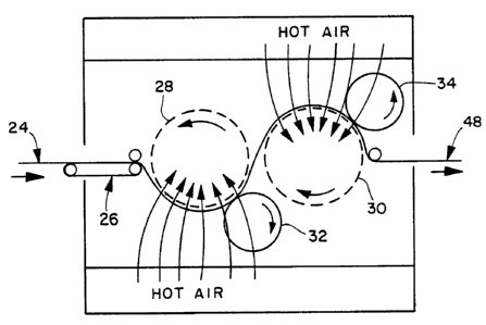
In Figure 2 the coform web 24 is shown being subjected
to a perforated drum-through air thermobonding process.
The coform web 24 is fed via conveyor 26 to a pair of
perforated drums 28 and 30 where the web is heated further
by hot air which is directed onto and through the web 24
and drums 28 and 30. Depending on the melting point of the
microfibers, the temperature of the hot air and the dwell
time of the web on the drums 28 and 30, sufficient melting
and fusion of the microfibers may or may not take place.
Optionally, therefore, calendering rolls 32 and 34 may be
used in conjunction with the perforated drums 28 and 30 to
further compress the softened web material. In either
event, however, the temperature and pressure should be
adjusted so as not to degrade the staple fibers which
--10--
i~
"
1338204
should remain intact throughout the process. Accordingly,
the staple fibers should have a melting point at least 10C
greater than the melting point of the microfibers.
A second means for converting the coform web into the
composite sheet of the present invention is shown in Figure
3 of the drawings. The coform web 24 is fed on conveyor 36
through a bank of infrared heaters 38 to again soften the
microfibers of the web 24. The web 24 is then fed through
a pair of calender rolls 40 and 42 to compress and fuse the
microfibers into a sheet-like layer. To aid the process,
an optional air slot heater 44 can be directed at the top
of calender rolls 40 and 42 to provide additional heat to
the web 24.
After the web 24 has been heated and compressed, the
lS densified web then passes over chill roll 46 to quench the
compressed molten microfiber sheet which at this point no
longer resembles a nonwoven web since the microfibers have
been melted and fused together. From the chill roll 46 the
material, which is now referred to as a composite sheet
material 48, is wound up on wind-up roll 50.
Alternatively, the composite sheet material 48 can be
subjected to further processing depending upon the end use
and design criteria of the material.
Given the versatility of the present invention and its
components it is possible to use numerous combinations of
equipment and processing steps to produce the composite
sheet material. Temperatures and pressures will vary
depending upon the properties of the microfibers and staple
fibers chosen. In any event, however, the staple fibers
should have a melting point at least 10C higher than the
melting point of the microfibers and the two components
should be adhesively compatible.
In addition to the base components of microfibers and
staple fibers, other constituents may be added to the
coform web. For example, binders (powdered or otherwise)
may be added to the web to enhance the binding and fusion
--11--
13~820~
of the microfibers to themselves and to the staple fibers
as well. Pigments, UV stabilizers, fire retardants and
other additives may also be incorporated into the web
material. Furthermore, blends of different microfibers
and/or staple fibers may be used to form the composite
sheet material of the present invention. In the case of
dispersing powdered adhesives as a binding agent for a dry
layered staple fiber composite, only low basis weight webs,
less than 100 g/m2, can be made with uniform distribution
of staple fiber and adhesive.
The surface of the composite sheet material may be
varied by varying the temperature, the degree of
calendering and the surface texture/pattern of the
calendering rolls. When a through-air thermobonding
technique is used (such as is shown in Figure 3 without the
optional calendering rolls 32 and 34), the exterior surface
of the composite sheet material will have a fabric-like
har.d. Similar fabric-like textures can also be achieved
through the use of calender rolls with embossed surfaces.
In contrast, a very smooth shiny surface can be achieved by
using smooth surface calender rolls. Lastly, smooth and
embossed calender rolls can be used in pairs to create a
composite sheet material that is smooth on one side and
more fabric-like on the other.
The strength, tear-resistance and durability of the
composite sheet materials of the present invention are
believed to be due to the void volume of the material as
well as the combination of the staple fibers, the degree of
melting and fusion of the microfibers and the adhesion of
the melted and fused microfibers to the staple fibers. The
use of the air laid process allows uniform distribution of
the bonding microfibers into the composite sheet material
of the present material. As a result in the present
invention, uniform composite sheet materials can be
achieved at any basis weight.
-12-
1338204
Prior to the heat and pressure process, the coform web
24 is a well defined fibrous structure. The fiber
structure of the microfibers and the staple fibers can be
readily discerned. Such materials do not have the
requisite strength, durability and tear resistance that are
required in tough end use applications such as abrasive
backing materials, industrial belting materials, laminate
backers, and geotextiles. Their open structures and
abundant pores also make such coform materials poor
substrates for supporting adhesives in abrasive
applications.
In contrast, it is possible to subject the coform web
to so much heat and pressure that the microfibers melt
completely out to form a film reinforced by the staple
fibers. In this form, the material has very few or no
pores and the staple fibers are completely surrounded by
the solidified microfibers. As will be shown in the
examples and data to follow, in this state the material is
also lacking in sufficient tear resistance and strength.
Once a tear has been started in such a material, the
continuous nature of the film-like material seems to
encourage the propagation of the tear despite the presences
of the staple fibers.
The composite sheet material of the present invention
lies between these two extremes and possesses strength,
durability and tear resistance properties well above those
exhibited by the materials at the two extremes. It is
believed that these improved properties are due to the
plurality of voids which are formed within the partially
melted and fused microfibrous portion of the structure.
Referring to Figures 5 and 6, the composite sheet material
10, which is comprised of the melted out microfibers 12 and
still intact staple fibers 14, czn be seen to have a
plurality of voids 16 on its surface and throughout the
structure. It is believed that these voids act as tear
stops to help retard further tearing once a tear has begun.
-13-
1338204
Typically, tears start along the edge of a material,
especially in the use of abrasive belting materials.
Testing has indicated that more force is needed to start a
new tear than to continue the tearing action once it has
been started. A case in point is the coform web which has
been melted out to a film-like structure. This structure
will easily continue a tear once it has been started. In
contrast, the composite sheet material of the present
invention has a plurality of voids dispersed throughout its
structure. Every time a tear encounters one of the voids,
it is akin to starting a new tear which requires more
force. As a result, the tear strength of composite sheet
the material is superior to that of the coform web or the
coform web which has the microfibers melted out into a
film-like material. Support for this proposition is found
within the following examples.
Examples
Numerous staple coform webs were prepared from a
number of staple and microfiber materials in a variety of
microfiber to staple fiber ratios. These samples were then
subjected to varying amounts of heat and pressure to melt
out the microfiber portion of the web into a sheet-like
material containing the staple fibers and a certain percent
void volume. The samples were then subjected to slit
trapezoidal tear and strip tensile tests to determine their
strength.
The percent void volume for the sample~ was determined
from the following equation and procedure:
% void volume = (1 _ dT ) 100
p
dT = the apparent density of the composite. This is
determined by carefully weighing and measuring the
length, width, and thickness of a rectangular piece of
-14-
1338~0~
the composite. The apparent density is the weight in
grams divided by the volume in cubic centimeters.
dp = the absolute density of the composite. The absolute
density is calculated from the weight fractions of the-
various fiber components and their respective absolute
densities, i.e. the reciprocal sum of the volume
fractions in cubic centimeters for one gram of
composite.
It is important to note that when the thermoplastic
microfibers used to form the web materials are heated, they
do not melt at a specified temperature. Instead, as their
temperatures increase, they begin to soften and lose their
shape. As they do so, they become tacky and moldable. The
fibers continue to lose their shape until finally, they
join together into a contiguous sheet. As stated
previously, to ensure the integrity of the staple fibers
during the formation of the composite sheet material, the
melting point of the staple fibers should be at least 10C
higher than the melting point of the microfibers. The
melting points reported herein for the various microfibers
and staple fibers were obtained from the specification
sheets supplied by the resin manufacturers. These melting
point values were then checked using a Fisher-Johns melting
point apparatus in accordance with ASTM test method D795.
All melting points were at normal atmospheric pressure.
Example I
Meltblowir.g equipment similar to that described in
U.S. Patent No. 4,100,324 was used to form the meltblown
adhesive microfibers of Example I. Staple fibers were
added to the meltblown stream through a picker roll and
secondary air system as illustrated in Figure 1. The
microfibers were formed from EASTOBOND~ FA 300 polyester
resin which is available from Eastman Chemical Products,
1338204
Inc., of Kingsport, Tennessee, and which has a melting
point of 155C. The extruded fibers were continuous in
length with diameters in the range of 2 to 10 microns and
with the majority of the fibers having diameters in the 4
to 6 micron range. The staple fikers were made from KODEL~
431 polyester which is available from Eastman Chemical
Products, Inc., of Kingsport, Tennessee. The polyester
staple fibers were approximately 38 mm in length with a
denier of 15 and a melting point of 237C. Mixing of the
microfibers to staple fibers was in a weight ratio of 30:70
and the homogeneous mixture of staple and microfibers was
collected on a rotating drum to form a low density web
having a basis weight of 320 grams per square meter (g/m2).
The web was then placed in a heated hydraulic press (PHI
model 75MR-253C-Y3-C from Pasadena Hydraulics, Inc., of
South Elmonte, California) at a temperature of
approximately 143C and a pressure of 26.2 x 10 N/m for a
period of 4 seconds.
Note that the press temperature of 143C was below the
melting point of both the microfibers (155C) and the
staple fibers (237C). By using a much higher pressure, a
lower temperature can be used to melt out the microfibers
while still keeping the integrity of the staple fibers
intact. Thus, the staple coform web can be transformed
into the composite sheet material by at least one of
several ways. First, only heat can be applied to transform
the material. In this case the temperature of the heat
would be between the melting points of the microfibers and
the staple fibers. A second method would involve using
heat, again at a temperature between the melting points,
and a low to moderate amount of pressure. This combination
would speed up the transformation of the material, thereby
decreasing the processing time. Lastly, the material can
be transformed by using a high degree of pressure which
will allow the temperature to be dropped even below the
melting point of the microfibers. Note that with each
-16-
1338204
method the exact temperature and/or pressure will depend
upon the properties of the microfibers and staple fibers
being used.
As a result of the conditions within the press in
Example I, the microfibers were melted and compressed to
form an open cell-like, "honeycombed" composite structure
with the melted microfibers surrounding and adhering to the
staple fibers. As can be seen from the scanning electron
microscope photographs of Figures 6 and 7, the cell-like
openings or voids were uniformly distributed throughout the
structure and yielded a composite sheet material with a
void volume of 45 percent using the method of calculation
outlined above. The sample composite of Example I had a
machine direction (MD) and cross direction (CD) strip
tensile strength of 45 kg/25mm and 36 kg/25mm respectively
as calculated using TAPPI method T404-OS-61. MD and CD
slit trapezoidal tear resistances were 24 kg and 10 kg
respectively. In this and all other examples, the MD and
CD slit trapezoidal tear resistances were calculated using
ASTM test method D1117, Section 14, Part 32 modified as
follows:
a) specimen cut, 1" x 6".
b) the 1" wide base of the trapezoidal template is
aligned with one 6" edge of the specimen for
marking and slitting.
c) only the maximum tensile value is reported for
each specimen.
d) machine direction refers to a propagated tear
across the machine direction, i.e., as tearing in
the cross direction of the web.
Example II
A coform material of the same blend as Example I was
used in Example II except that it was subject to a heat and
pressure process similar to that shown in Figure 3. A roll
of the material having a basis weight of 290 g/m2 was
133820~
carried on a teflon coated fiberglass belt under infrared
heaters to raise the web temperature to 188C and soften
the microfibers. The web was then passed through a smooth
calender with a nip pressure of 2004 kg per linear meter
and a speed of 6.1 m/min. The compressed composite, while
still on the teflon coated fiberglass belt, was next passed
over a chill roll at 18C and then released from the belt.
The resultant composite sheet material, as with Example I,
was strong and tear resistant. The material had a void
volume of 48 percent, a machine direction (MD) strip
tensile strength of 36 kg/25mm, a cross direction (CD)
strip tensile strength of 29 kg/25mm, a MD slit trapezoidal
tear strength of 19 kg and a CD slit trapezoidal tear
strength of 10 kg.
Example III
Example I was repeated using DYNAPOL~ S-360, a
polyester adhesive resin from Dynamitt Noble America, Inc.,
of Rockleigh, New Jersey, in place of the EASTOBOND~ FA 300
as the meltblowing microfiber resin. The meltin~ point of
the polyester adhesive resin was 200C. The staple fiber
composition, the mixing ratio, and the total basis weight
were the same as in Example I. The resin for the adhesive
microfibers processed well and the resultant composite was
formed at 190C at the same pressure and for the same
amount of time as used in Example I. Void volume for the
composite was 34 percent, the MD and CD strip tensile
strengths were 37 kg/25mm and 28 kg/25mm respectively and
the MD and CD slit trapezoidal tear strengths were both 15
kg.
Example IV
In Example IV numerous samples with the same staple
fiber and microfiber compositions as Example I were run
using varying ratios of microfibers to staple fibers.
These samples were then tested for tear resistance and
-18-
133820~
tensile strength to determine acceptable ratios of
microfibers to staple fibers. Testing indicated that the
upper and lower limits for the ratio of fibers were from 20
parts -microfibers and 80 parts staple fiber to 65 parts
microfibers and 35 parts staple fiber on a per weight
basis. With less than 20 parts microfiber the bonding of
the staple fiber was found to be inadequate. Above 65
parts microfibers there was insufficient staple fiber
present to provide good tensile strength and tear
resistance.
Example V
Having determined the proper weight ratio of
microfibers to staple fibers, the purpose of Example V was
to determine the appropriate range of void volumes
necessary for a composite with good strength. Samples were
made from the same fiber compositions as in Example I;
i.e., a basis weight of 290 g/m2 with a 30/70 weight ratio
of microfibers (EASTOBOND~ FA 300 polyester resin) and
2Q polyester staple fibers (KODEL~ 431, 15 denier, 38 mm).
Void volumes in the composite sheets were varied by
adjusting the bonding temperature while maintaining the
pressure and time within the hydraulic press constant.
Data for each of the various samples is shown in Table I
and the percent void volume versus slit trapezoidal tear
strength in the machine direction is shown in graph I.
Note that the slit trapezoidal tear strengths given in
Table I and shown in the graph of Figure 8 are in kilograms
per a basis weight of 290 grams/square meter. For
uniformity, these values were converted to a 100
gram/square meter basis weight using a conversion of the
ratios as follows;
--19--
1338204
measured slit trap (kg) = slit trap (kg)
290 g/m 100 g/m
slip trap (kg per 100 g/m2) = measured slit trap (kg) x 100
290
-20-
133820~
e ~
~; _ O
X ~ E Ei ~
--
~ _) r~l N O O~ t-- ~D Lr) ~ ~ a~
~ o ~ N ~ ~1 ~1
E~ --
cr
-
~ E
H ~t~
~: O ~ ~ ~
,-- ~ o~ ~ ~ Il')Lt)~ O
~;
H
U~
~ .
-- . . . .. . .
~ O O
H ~¢
aH
0 3 ~ O
d~ ~
5 # ~ m c~ a ~ H 1~
1338204
- As can be seen from the data in Table I and its
depiction in graph form in Figure 8, a very dramatic
increase in slit trapezoidal tear strength (MD) was
achieved at select void volumes. For materials of the
present design, it is desirable to have slit trapezoidal
tear strengths in the machine direction which are greater
than or equal to 5 kg per 290 g/m2 (1.7 kg per 100 g/m2).
Referring to graph I, this criterion was met when the void
volume was between approximately 33 and 55 percent.
However, the most dramatic increase in slit trapezoidal
tear strength took place when the material had a void
volume between approximately 38 and 45 percent. In this
range the tear strength was as hish as 20.8 kg (7.2 kg per
100 g/m ) which is over four times the desired base level
of 5 kg (1.7 kg per 100 g/m ).
In contrast to the excellent strength exhibited by
materials with void volumes in the 33 to 55 percent range,
materials outside this range were weak. At a low void
volume the material was more like a film with very few
voids and a low trapezoidal tear strength. Similarly, at
high void volumes, i.e. greater than 55 percent, the
material more closely resembled a nonwoven web with a very
open pore structure. Here again the slit trapezoidal tear
strength was low. Only when the composite sheet materials
had void volumes in the range of about 33 to about 55
percent were the desired properties achieved.
Example VI
A composite sheet material was made from a 30/70
weight ratio of polyamide microfibers (melting point 140C)
and nylon staple fibers (melting point 247C). The
microfibers were made using Union Camp UNIREZ~ 2665 hot
melt polyamide resin in meltblowing equipment similar to
that described in U.S. Patent 4,100,324. The microfibers
were continuous in length with diameters in the 4 to 6
micron range. The staple fibers were nylon 66 from ICI
-22-
133820~
Fibers of Greensboro, North Carolina, and averaged 38 mm in
length with a denier of 15. The staple fibers were added
to the microfibers as they were formed through a picker and
secondary air stream as was previously described and
illustrated in Figure 1. The staple coform mixture was
collected on a rotating drum to form a low density web
having a basis weight of 320 g/m2. The web was then placed
in a heated hydraulic press at approximately 145C at a
pressure of 18.6 x 10 N/m for 45 seconds. The heat and
pressure caused the microfibers to melt to form a void-
filled layer around the staple fibers. The resultant
composite sheet material had a "honeycombed" structure with
open cell-like units and a void volume of 45 percent. MD
and CD strip tensile strengths were 33 kg/25mm and 22
kg/25mm respectively while the MD and CD slit trapezoidal
tear strengths were respectively 10 kg (3.2 kg per 100
g/m ) and 11 kg (3.4 kg per 100 g/m2).
The flexible tear resistant composite of sheet
material of the present invention also proved to be an
excellent materi~l for lamination to aesthetically
appealing or functional surface materials. For example, a
lightweight, weak, soft leather was heat laminated to the
composite sheet material of the present example. The
polyamide microfibers served as the adhesive for the
leather and composite sheet laminate. The resultant
material was a flexible tear resistant sheet with a soft
leather surface. The laminate was made in one step with
process conditions as described on Example No. VI and the
same physical properties. A leather book cover or table
covering are but two product applications for a flexible
tear-resistant composite sheet-leather laminate. The
aesthetically appealing surfacing materials are not limited
to leather and can include cloth, foil, cellulose, ceramic,
or synthetic fabrics.
-23-
1338204
Example VII
In addition to the previous samples, several other
samples were also prepared in accordance with the methods
and design parameters of the present invention. A summary
of these examples is provided within Table II. A total of
thirteen samples were prepared from a variety of
microfibers and staple fibers with basis weights ranging
from 85 to 500 g/m and microfiber to staple weight ratios
of 20/80 to 65/35. Testing of these samples confirmed that
lG the staple fibers should be at least 10 mm in length for
good strength properties in the composite. The adhesive
microfibers must melt and flow at a temperature that does
not destroy the intrinsic strength characteristic of the
staple fibers. Therefore the melting point of the staple
fibers should be at least 10C greater than the melting
point of the microfibers.
-24-
1338204
o o ~ Ln
Z I o ~ ~ L~
o o o
~ I o
o o
o In U~
~, I o
o o o
~1 0 ~ 1~
o o
C~
o o ~ U~
I ¦ O (~)
o o o o
U~ o
C~
o
o o U~
G ¦ C~J ~ ~r
C~ C
., ~ o o o
X ~
o o
~1 '`~ o~
I o o o
E
E c~J
E E
~~ E c
s) E
~_~ 00 N E
~0 0 00 ~ ^ E E C
t~ O ~ ~~ ct)--~ ~ t E E E E O
a;_I ~ ~ ~ Ln ~s t a) E L~ o E--
E
X ~ r ~ r_ y
o ~D ~ a.) ~ C _ aJ
3 ~ O O ~
E-- O ~ ~ D ~ -- ~ c _ _ a~ --
s G ~ ~ J
O ~ ~ z r~C ~ O
z ~a) m ~ ~ ~ ~ aJ ~ L~ o a~ ~ ~
o ~ raJ _ ~ ~ ~ ~ ~) C~l ~) t~ L~
---- S:~, J ~ ~J ~ ~ ~,Z
_ 3c~) r) E ~
11 o J
o ~ ~ , , o o o o ~. E
E n _ o o o o o o o LLJ _ o o ~, ~, >, ~
o ~ ~5 c~ c~ cL. c~ ~ ~ c~ _ ~a ~ ~ Z ~ Z ~Y CC ~
G . . . . . . . c~ . . . . . . . .
133820~
Having thus described the invention in detail, it
should be apparent to those skilled in the art that various
modifications and changes can be made without departing
from the spirit and scope of the following claims.
-26-