Note: Descriptions are shown in the official language in which they were submitted.
1338206
IMPROVED PORTABLE ROTARY POWER TOOL
BACKGROUND OF THE INVENTION
This is a division of copending Canadian Patent
Application Serial No. 581,729 filed October 31, 1988.
The present invention relates generally to power
tools, and more particularly provides a substantially improved
power head assemblyl and vibration reducing apparatus, for a
portable rotary power tool such as a flexible line trimmer.
Portable, gasoline engine driven rotary power tools
such as brush cutters, lawn edgers, flexible line trimmers and
the like typically comprise an elongated hollow shaft to one
end of which a rotary cutting assembly is operatively mounted.
A power head assembly, including the engine, is mounted on the
opposite end of the shaft and typically comprises a protective
shroud structure which envelops all or part of the engine, a
gas tank, and a recoil starting mechanism incorporating the
usual starter rope and pull handle components. The engine
drives the cutting assembly, either ~irectly or through a
clutch mechanism, via a flexible drive shaft structure
extending through the hollow shaft. To assist in properly
guiding the cutting element during tool use, a pair of
operator handle elements are typically secured to the tool in
appropriate locations thereon. Additionally, a shoulder strap
is often used to support the weight of the tool, the strap
having an outer end portion which i-s releasably connectable to
a small rigid clamp member or the like securéd to shaft.
While gasoline driven tools of this general type
`~ -2- 1338206
and configuration have proven to be quite useful, and
immensely popular, a variety of problems, limitations and
disadvantages may still be found in many of them relating
to, among other things, structure, operation, safety,
fabrication cost effectiveness, operating comfort, and
maintenance and service accessability.
For example, because of the need to design the
power head assembly to be at the same time light in weight,
compact, and cost effective from material and fabrication
standpoint, the resulting power head assembly can be
frustratingly difficult and laborious for the average
consumer to work on. Even minor engine adjustments, such as
resetting the carburetor idle and operating speed adjustment
screws, is often annoyingly hindered by the need to
disassemble and remove various other power head components
to even reach the carburetor. At the other end of the
maintenance spectrum, major engine teardown and removal is
often simply beyond the capabilities of the average tool
user due to the sheer complexity and intricacy with which
many conventional power heads of this general type are of
necessity assembled.
Conventional attempts to alleviate to some degree
this component access problem have, in many instances, left
certain engine components exposed in a manner, though
increasing their accessability, increasing the likelihood
that such exposed components will be accidentally bumped and
damaged during tool use, and giving the overall power head a
somewhat ungainly and "jury rigged" exterior appearance. As
but one example of this problem, the~engine's carburetor and
associated air filter structure are often allowed to
protrude outwardly of the engine's shroud structure for
accessability purposes, thereby rendering these components
highly vulnerable to damage.
Another example, relating both the component
accessability and safety, arises in conjunction with the
recoil starter mechanism which is typically difficult to
remove and, when the need arises to replace its starter
1338206
rope, difficult, awkward and sometimes unsafe to work on. As
is well known, the problem here lies with the conventional
necessity of hand winding the starter pulley against the
biasing force of its associated torsion spring, and then
holding the wound-up pulley with one hand, to keep the torsion
spring from flying off, while attempting to rethread and knot
a new starter rope onto the pulley with the other hand.
Apart from these and numerous other problems
typically associated with conventional power head sections of
tools of this general type, it has been found that a
surprisingly high amount of shaft vibration is often
transmitted to the tool operator's body through the shoulder
strap secured to the tool shaft despite the flexibility of the
strap. This transmitted vibration can be both annoying and
tiring, and it would be quite desirable to eliminate or at
least substantially reduce it in a simple, inexpensive manner.
In view of the foregoing, it is accordingly an object
of the present invention to provide improvements which
eliminate or minimize above-mentioned and other problems,
limitations and disadvantages commonly associated with
conventional portable rotary power tools of this general type.
SUMMARY OF THE INVENTION
In accordance with one aspect of the invention there
is provided a carburetor choke plate and air filter assembly
comprising: an air filter housing having an open front end,
a back wall, a side wall portion having air inlet openings
formed therein, a notch formed in said~side wall portion and
extending rearwardly from said front end, and means defining
a support channel within said housing which is peripherally
bounded by a portion of the interior surface of said side wall
portion; a choke plate having a choke opening formed centrally
therethrough and adapted to be placed over the' air inlet
opening of a carburetor, said choke plate being received in
said open front end of said air- filter housing; fastening
means for releasably securing said air filter housing to said
choke plate; an elongated, plate-like choke lever having a
133820~
-3a-
central portion pivoted to the rear side of said choke plate,
and inner end portion positioned to be moved across said choke
opening to selectively block and unblock the same, and an
outer end portion disposed in and projecting outwardly through
said housing notch; and a strip of resilient air filter
material operatively received in said support channel, said
strip having a front side edge portion which resilient bears
against said outer end portion of said choke lever and an
adjacent rear side portion of said choke plate in a manner
forming around said outer choke lever end portion a resilient
dust seal which moves therewith.
In carrying out principles of the present invention,
in accordance with preferred embodiments thereof, a
representative internal combustion engine driven portable
rotary power tool, in the form of a flexible line trimmer, is
provided with a modular power head assembly mounted on one end
of the hollow trimmer shaft and utilized to rotationally drive
a cutting head assembly mounted on the opposite end of the
shaft.
In one embodiment thereof, the power head assembly is
formed, proceeding from back to front along the assembly,
from four releasably interconnected modules - an engine
1338~06
_ -4-
module, a fan housing module, a starter module, and a
coupling module.
The engine module comprises a specially designed
shroud having an open front end, a top wall, a bottom wall,
a pair of opposite side walls, a thickened upper rear
support wall section which is forwardly inset and extends
downwardly from a central portion of the top wall, and a
vertically intermediate wall which extends rearwardly from
the bottom of the support wall and defines with rear
portions of the bottom and side walls a muffler chamber
having an open back end over which a suitable muffler guard
may be connected.
The top wall of the shroud is downwardly inset to
form a top well portion of the shroud, and the open bottom
end of a shell member is sealingly secured to the periphery
of the well portion to define therewith a fuel tank portion
of the engine module.
A rear portion of the top wall defines with the
intermediate wall and the support wall a back end recess in
the shroud. A carburetor and an associated air filter
housing are disposed within this recess to protect these
components from damage, while at the same time providing
easy access thereto. The carburetor is secured to the outer
surface of the support wall over a fuel-air mixture passage
extending inwardly therethrough, a reed valve member being
operatively mounted on the interior surface of the support
wall over the inner end of the fuel-air mixture passage.
The engine module also com~prises a small single
cylinder, air cooled, two stroke~ cycle gasoline engine
having a crankcase with an open rear end portion, a piston
and cylinder assembly secured to and depending from the
crankcase, and a muffler operatively supported on the
cylinder and projecting rearwardly therefrom. The
crankcase, cylinder and muffler portions of the engine are
disposed within the shroud and are removable through its
open front end. The open rear end of the crankcase is
bolted to the interior surface of the thickened support
~5~ 1~38206
wall, over the reed valve thereon, so that such support wall
supports the engine and defines a rear closure wall of the
crankcase. The cylinder extends below the intermediate
shroud wall, with the muffler projecting rearwardly into the
muffler chamber. The engine's crankshaft projects forwardly
through and beyond the open front end of the shroud, and is
provided at its forward outer end with a centrifugal clutch
assembly captively retained on the crankshaft by a nut-
threaded onto the outer crankshaft end.
The fan housing module comprises a fan housing
section removably secured to the shroud around its open
front end and enclosing the engine's flywheel which
coaxially circumscribes and is rotationally locked to the
crankshaft forwardly of the crankcase. The flywheel is
provided with a circumferentially spaced series of axially
extending cooling impeller blades which, during engine
operation, flows a supply of ambient cooling air rear
wardly across the cylinder and outwardly through the muffler
chamber, the ambient cooling air mixing with exhaust gas
discharged from the muffler to cool the exhaust gas. The
exhaust gas-cooling air mixture being discharged rearwardly
through perforations in the muffler guard.
The starter module comprises a starter housing
having a front wall, a side wall section extending
rearwardly from the periphery of the front wall, and an open
back end portion, the starter housing being releasably
connected to the open front end of the fan housing. A
tubular support post projects rearwardly from the front wall
of the starter housing and circumscribes a portion of the
engine's crankshaft between the clutch assembly and the
flywheel. Carried within the starter housing is a manual,
recoil type starting system which includes a starter pulley
rotatably carried on the support post and having front and
rear flanges between which a starter rope is wound, an outer
end portion of the starter rope extending outwardly thro~gh
a grommeted opening in the starter housing and being
operatively connected to a starter pull handle.
1338206
_ -6-
A hollow cylindrical drive hub projects rearwardly
from a central portion of the rear flange and is provided
with drive teeth operatively engageable with spring biased
starter dogs mounted on a forward portion of the flywheel.
An annular torsion spring circumscribes the support post, is
operatively connected to the starter pulley, and is retained
between the starter housing front wall and the front pulley
flange. The starter pulley is received within a generally
annular guide channel defined by guide members projecting
rearwardly from the front starter housing wall. The pulley
is captively retained on the support post by a small
retaining tab member secured to a thickened portion of the
starter housing by a small screw member. Accordingly, when
the starter module is removed from the balance of the power
head assembly, both the starter pulley and its associated
torsion spring are retained within the starter housing.
The installation of a starter rope on the starter
pulley is made significantly easier and safer by the pulley
and spring retaining operation of the tab member in
conjunction with circumferentially alignable notches formed
in the periphery of the rear pulley flange and one of the
pulley guide members. To install a starter rope on the
pulley, the pulley is wound up against the biasing force of
the torsion spring and then backed off approximately one
turn until these two notches are brought into alignment. A
small pin member or the like may then be inserted-between
the aligned notches to lock the pulley against rotation
caused by the wound up spring. Both of the operator's hands
are then freed to easily and safely install the starter
rope. After the rope has been installed, the locking pin
member may be removed to allow the spring to unwind and
automatically wind the new rope onto the starter pulley.
The coupling module, which is releasably
connectable to the front side of the starter module,
comprises a clutch housing which envelops the engine's
centrifugal clutch assembly and is provided at its front end
with an internal, rearwardly projecting support shaft
~ -7- 1338206
portion into which is molded a bearing structure including
an annular bearing and an annular bearing spacer. This
bearing structure coaxially receives and rotatably supports
a cylindrical coupling member which is rotationally locked
at a front end thereof disposed within the support shaft
portion to an end of the flexible drive shaft which extends
through the tubular trimmer shaft and is used to drive the
trimmer's cutting head assembly. A clutch drum is fixedly
secured to the rear end of the coupling member and outwardly
circumscribes the centrifugal clutch assembly. When the
rotational speed of the engine reaches a predetermined
level, friction portions of the clutch assembly are moved
radially outwardly therefrom to frictionally engage the
interior surface of the clutch drum to thereby rotate the
flexible drive shaft.
This modular power head assembly greatly
simplifies, in a very cost effective manner, the access to
and servicability of the internal power head components.
For example, simply by removing the coupling module, the
centrifugal clutch assembly is readily accessible, yet is
conveniently held on the balance of the power head assembly
by the retaining nut on the outer end of the crankshaft.
The exposed clutch assembly also captively retains the
starter and fan housing modules on the shroud. By removing
the clutch assembly, the starter assembly may simply be
pulled outwardly off the front end of the crankshaft.
Additionally, by then removing the fan housing screws and
the fan housing, both the flywheel and its associated
ignition module are exposed for inspection ana service. The
entire engine may then be removed simply by disconnecting it
from the shroud support wall and pulling it outwardly
through the open front end of the shroud. The carburetor
and its associated air filter structure, which are disposed
in the protective shroud recess and accessible therethrough,
may also be simply disconnected from the shroud's specially
designed supporting wall.
-8- 1~3 8 2 06
In a direct drive embodiment of the power head
assembly, the centrifugal clutch assembly is eliminated, and
a single fan housing and starter module is removably secured
to the open front end of the shroud. This single, forwardly
disposed module comprises a unitary housing section in which
the recoil starter system is captively retained, and a
coupling member is carried to drivingly interconnect the inner
end of the flexible drive shaft and the outer end of the
crankshaft.
In another version of the power head assembly, the
shroud is modified by eliminating the upper shroud wall
portion and a rear portion of the shroud's upper wall. A
separate fuel tank is suitably secured atop a front upper
portion of the shroud and has a rear portion which extends
rearwardly of the shroud support wall and is spaced upwardly
from the intermediate shroud wall to define therewith the
protective recess within which the carburetor and its
associated air filter structure are disposed. In yet another
version of the power head assembly, the shroud is modified in
essentially this same manner, and an operator handle is
secured to and positioned above the power head assembly. The
operator handle has a front end portion which is connected to
the housing structure disposed forwardly of the shroud, and a
rear portion defined by a fuel tank which is suitably secured
to an upper portion of the shroud and overhangs the carburetor
and its associated air filter structure.
-9 1338206
-
BRIEF DESCRIPTION OF THE DRAWINGS
The present invention taken in conjunction with the
invention disclosed in copending Canadian Patent Application
Serial No. 581,729 filed October 31, 1988, will be described
hereinbelow in conjunction with the aid of the accompanying
drawings in which:
Fig. 1 is a perspective view of a gasoline engine
powered flexible line trimmer that incorporates a variety of
structural, operational, maintenance and service
accessibility, cost reducing, and other improvements embodying
principles of the present invention;
-lO- 1338206
Fig. 2 is an enlarged scale perspective view of the
power head section of the trimmer;
Fig. 3 is an enlarged scale, partially cross-
sectional, and partially elevational view taken through the
power head section along Iine 3-3 of Fig. 2, with certain
engine components within the power head being schematically
depicted;
Fig. 4 is a somewhat simplified exploded side
elevational view of the power head section, with certain
portions thereof being omitted for illustrative purposes;
Fig. 5 is a fragmentary side elevational view of a
rear portion of the power head section taken generally along
line 5-5 of Fig. 2;
Figs. 6A and 6B are rear side elevational views of
the starter housing portion of the power head section, taken
along line 6-6 of Fig. 4, illustrating certain structural
and operational features of the recoil starting mechanism
disposed therein;
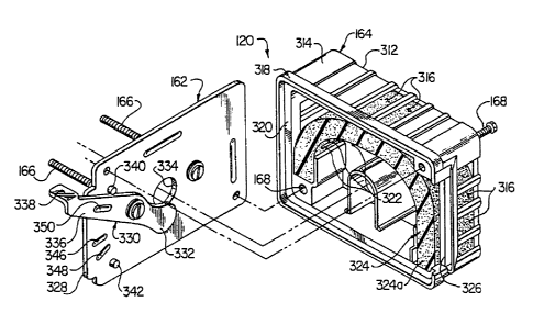
Fig. 7 is an enlarged scale perspective view of a
choke plate and air filter subassembly portion of the power
head section;
Fig. 8 is an exploded perspective view of the
subassembly of Fig. 7;
Fig. 9 is an enlarged scale fragmentary cross-
sectional view through the subassembly of Fig. 7, taken
along line 9-9 thereof;
Fig. 10 is an enlarged scale perspective view of a
vibration isolating shoulder strap connecting member secured
to a portion of the trimmer shaft which is illustrated in
phantom;
Fig. 11 is a cross-sectional view through the
connecting member taken along line 11-11 of Fig. 10;
Fig. 12 is a side elevational view of an alternate
embodiment of the power head section;
Fig. 13 is a side elevational view of a further
alternate embodiment of the power head section; and
1338206
--11--
Fig. 14 is an enlarged scale partial cross-
sectional view through a front end portion of the power head
section of Fig. 13.
DETAILED DESCRIPTION
In a preferred embodiment thereof, the present
invention provides a portable rotary power tool, in the form
of a flexible line trimmer 10 perspectively illustrated in
Fig. 1, in which a variety of unique structural,
operational, maintenance and service accessibility, cost
reducing, and other improvements are provided. Trimmer 10
has an elongated hollow shaft 12 which has operatively
mounted on its left or forward end a rotationally drivable
cutting head assembly 14 which is rotated at a high speed to
spin an outwardly projecting flexible trimming line segment
16 in a cutting plane which is essentially transverse to the
rotational axis of the head 14, and is utilized to trim
various types of vegetation into which the cutting plane is
moved. To protect the trimmer operator from the rapidly
whirling line segment 16, a protective shield member 18 is
also secured to the outer end of shaft 12, the shield member
18 being positioned generally above the cutting plane and
projecting rearwardly
toward the operator. To transmit rotational power to the
cutting head assembly 14, a uniquely configured and
operative power head assembly 20 is mounted on the right or
inner end of the shaft 12. A small, single cylinder
internal combustion engine 22 (Fig. 3~) is disposed within a
multi-section molded plastic shroud and housing structure
which, as also illustrated in Fig. 2, comprises a main
shroud 24, positioned at the rear of the powerhead assembly
20; a fan housing 26 removably secured to a front side
portion of the shroud 24 by mounting screws 28; a starter
housing 30 positioned at the front side of the fan housing;
and a clutch housing 32 pro~ecting forwardly from the
starter housing and secured to an inner end portion of the
shaft 12 in a manner subsequently described. Elongated
1338206
-12-
mounting screws 34 are extended-through a rear portion of
the clutch housing 32, through the starter housing 30 and
into a front portion of the fan housing 26 to thereby
removably mount the housings 30, 32 on the fan housing 26.
Coaxially circumscribing the shaft 12 immediately
ad~acent the outer end of the clutch housing 32 is a hollow
cylindrical rear operator handgrip 36 which is formed from a
suitable resilient material. At the forward end of the
handgrip 36 a molded plastic throttle lever housing 38 which
is removably clamped to the shaft 12, and is provided with a
pivotally mounted throttle lever 40 operatively connected,
via a cable element 42, to the pivotally mounted throttle
arm portion 44 (Fig. 5) of the engine's externally mounted
carburetor 46. The cable 42, as best illustrated in Fig. 1,
is extended through an axial passage (not illustrated)
formed in the handgrip 36, and then enters the fan housing
26 at location 48. As best illustrated in Fig. 5, the cable
42 exits the rear shroud 24, adjacent the carburetor 46, and
is connected at an end portion thereof to the throttle arm
44.
Clamped to the shaft forwardly of the throttle
lever housing 38 is a forward operator handle 50 which is
used by the trimmer operator in conjunction with the rear
handgrip 36 to precisely control the movement of the trimmer
cutting plane. Also clamped to the shaft 12, between the
housing 38 and the control handle 50, is a specially
designed, -vibration reducing shoulder strap connector
assembly 52 which, in a manner subsequently described is
connectable to an operator shoulder strap 54, the strap 54
being used by the operator in a conventional manner to
assist in comfortably supporting the weight of the trimmer
10 .
Referring now to Figs. 2-4, it can be seen that the
shroud and housing portions 24, 26, 30 and 32 are "stacked'~
in a front-to-rear direction along the rear end of the shaft
12 and, as previously mentioned, are easily separable from
one another by removing the mounting screws or bolts 28 and
~ -13- 1~3~ZOS
34. In side elevation, the main shroud 24 has a generally
rectangular configuration, while an upper portion of the fan
housing 26 combines with the fan and clutch housings 30, 32
to provide the overall housing structure with a generally
frustroconically-shaped forward nose portion that gives the
multi-section housing structure a pleasing, streamlined
configuration.
The main shroud 24 has an open front end 56, and a
vertically elongated, generally rectangular cross-section
defined by an upper wall 58, a lower wall 60, and a pair of
side walls 62 and 64. Extending downwardly from the upper
shroud wall 58 is a substantially thickened upper rear wall
section 68 that is connected at its lower side to a
rearwardly extending vertically intermediate wall 70.
The interior of the main shroud 24 opens outwardly
through the open front end 56 thereof, and additionally
opens outwardly through a lower rear end opening 72 defined
by lower side portions of the side walls 62 and 64, the
intermediate wall 70, and a rear portion of the lower wall
60, these particular wall portions defining in the shroud 28
a lower rear internal cavity 74. Additionally, an upper
rear recess 76 is formed in the shroud 24 by the wall
section 68, the vertically spaced walls
58 and 70, and sloping rear tab portions 78 of the side
walls which are spaced vertically apart from one another and
project inwardly beyond the walls 58 and 70. As
illustrated, the upper rear recess 76 is accessible from the
back of the shroud 24, and from the opposite sides thereof
between opposed pairs of the side wall tab portions, and is
bounded at it inner end by the thickened upper rear wall
section 68.
The fan housing 26 which is secured as previously
described to the front end 56 of the main shroud 24, has an
open front end 80, and an open rear end 82. The starter
housing 30 has an open rear end 84 and a front wall 86 from
a central portion of which a hollow cylindrical support post
member 88 rearwardly extends. The forwardly and laterally
-14- 1338206
inwardly tapered clutch housing 32 has an open rear end 90,
and an open front end 92 from which a hollow cylindrical
support shaft portion 94 rearwardly extends.
Referring now primarily to Figs. 3 and 4, the
engine 22 is a single cylinder, air cooled, two stroke cycle
engine, which, with the exception of certain components
subsequently described is disposed within the multi-section
shroud and housing structure described above. The primary
components of the engine 22 comprise a finned cylinder 100;
a piston 102 received in the cylinder for reciprocation
therein along a vertical axis as viewed in Figs. 3 and 4; a
crankshaft assembly 104; a crankcase 106; a flywheel 108
having a circumferentially spaced series of axially
extending cooling impeller blades 110 thereon; a centrifugal
clutch assembly 112; an ignition module 114; a spark plug
116; a muffler 118; the carburetor 46; and an air filter
housing and choke plate assembly 120. Crankcase 106 has a
hollow rear portion 122 with an open back end 124, an open
lower side 126, and a forwardly projecting, hollow
cylindrical bearing support portion 128.
As will be seen, the main shroud 24, in addition to
enveloping and protecting a rear portion of the engine 22,
uniquely performs a variety of functions in the powerhead
assembly 20. One of these important functions, performed by
the shroud's thickened wall section 68 is to mount and
support the engine 22 as will now be described. The open
back end portion 124 of the crankcase 106 is bolted, over a
gasket 130, to the inner side surface of the thickened wall
section 68, around an inwardly projecting boss portion 132
thereof, by means of four mounting bolts 134 (only two of
which are visible in Fig. 4) which are positioned in the
rear shroud notched area 76 and are extended forwardly
through the wall section 68 and fastened into the crankcase
end portion 124.
The thickened wall section 68 also serves to
externally mount, within the notched area 76, the carburetor
46 and the filter and choke plate assembly 120, in a manner
1338206
-15-
subsequently described, the carburetor 46 abutting a
rearwardly projecting end portion 135 of boss 132 as best
illustrated in Fig. 3. It can be seen in Fig. 3 that this
thickened wall section 68 defines a rear closure wall of the
rear portion 122 of crankcase 106, while a suitably
configured boss opening 136 also defines a fuel-air mixture
passage which interconnects the carburetor outlet with the
interior of the rear crankcase portion 122. The boss 132
also is conveniently used to mount, over the inner end of
the passage 136 a schematically depicted crankcase reed
valve 138. Before describing various other functions
performed and advantages provided by the main shroud 24, a
detailed description of the interconnection and relative
positioning of the previously mentioned engine components
will now be given.
The upper end of the finned cylinder 100 is
suitably bolted, over a sealing gasket 140, to the open
lower side 126 of the crankcase 106, with the bottom-mounted
spark plug 116 projecting downwardly through a suitable
opening 142 formed in the lower shroud wall 60. Spark plug
116 is operatively connected to the ignition module 114 by
suitable wiring 144, the ignition module being positioned
generally within a lower portion of the fan housing 26, and
being secured to a forwardly projecting connecting block
portion 146 of the cylinder 100 by an elongated mounting
screw 148.
Cylinder 100 is provided in a right side portion
thereof with a suitably configured exhaust gas discharge
opening 150 which receives the inlet end 152 of the muffler
118. Exhaust gas discharged from the cylinder 100 is flowed
through the outlet opening 150 into a perforated cylindrical
muffler liner 154 into the interior of the muffler body.
The muffler body is formed from two partially nested
horizontal sections 118a and 118b, the section 118a having
outwardly deformed portions which define side outlets 156 in
the muffler body. Exhaust gas entering the interior of the
muffler body through the liner 154 is discharged rearwardly
~ -16- 1338206
through these side outlets 156 and then flowed rearwardly
through rear wall perforations 158 formed in a hollow molded
plastic muffler guard 160 secured to the shroud 24 over its
lower rear end opening 72.
The filter and choke plate assembly 120 includes a
metal choke plate 162 positioned rearwardly of the
carburetor 46, and an air filter housing 164 positioned
rearwardly of the choke plate. The plate 162 is secured to
the thickened shroud wall section 68 by a pair of elongated
mounting screws 166 which draw the plate 162 against the
back end of the carburetor 46 to clamp it into operative
engagement with the rearwardly projecting boss portion 134
so that the fuel-air mixture produced by the carburetor
flows into the crankcase via the boss opening 136 and across
the reed valve 138. The filter housing 164 is secured to
the choke plate 162 by means of a pair of mounting screws
168 extended through the filter housing 164 and fastened
into the choke plate 162. Fuel is supplied to the
carburetor 46, in a manner subsequently descri~ed, through a
flexible fuel line 170. Crankshaft assembly 104
has a relatively large diameter inner longitudinal shaft
section 172~which extends coaxially through the crankcase
bearing support portion 128 and is rotatably supported
therein by a bearing structure that includes an inner crank
bearing 174 carried by the shaft section 172, and an outer
crank bearing 176 retained within an outer end portion of
the bearing support portion 128 which projects forwardly
into the fan housing 26. The left end of the inner shaft
section 172 tapers, as at 178, to a smaller diameter outer
longitudinal shaft section 180 which extends centrally
through the starter housing 30 and into the clutch housing
32, and is provided with an externally threaded outer end
portion 182.
The flywheel 108 is positioned within the fan
housing 26 and coaxially circumscribes a longitudin-ally
central portion of the crankshaft including its tapered
portion 178. The flywheel is keyed or otherwise
1338206
-17-
rotationally locked to the crankshaft for rotation
therewith, and its impeller blades 110 function during
flywheel rotation by the crankshaft to draw ambient cooling
air 184 into the interior of the power head assembly 20
through a series of side wall slots 186 formed in the
starter housing 30. The air 184 entering the powerhead
assembly interior is forced rightwardly across the finned
cylinder 100 and the muffler 118, through the lower rear
shroud cavity 74, to cool the same. Cooling air 184
rightwardly traversing the muffler 118 mixes with exhaust
gas 186 being discharged therefrom to cool such exhaust gas.
The cooling air-exhaust gas mixture 184, 186 is then
discharged rearwardly from the muffler guard 160, through
the rear end wall perforations 158 therein, as illustrated
in Fig. 3. This conveniently directs the cooled exhaust
gas-cooling air mixture rearwardly away from the trimmer
operator.
Affixed to the inner end of the crankshaft section
172 is a crankshaft counterweight member 188 which is
disposed within the rear portion 122 of the crankcase 106.
This counterweight section of the crankshaft assembly 104 is
provided with a crank pin 190 which is operatively
interconnected with the piston 102 by a connecting rod 192.
The clutch assembly li2 is coaxially mounted on an
outer end portion of the crankshaft section 180 and is
retained thereon by a nut 194 fastened onto the threaded
crankshaft end portion 182. An annular clutch washer 196 is
also coaxially mounted on the shaft section 180 and bears
against the rear side surface of the clutch assembly 112.
An inner end portion of an elongated
flywheel counterweight member 198 is slidably retained on
the shaft section 180 and bears against a central from side
surface portion 200 of the flywheel 108. Counterweight 198
is captively retained on the shaft section 180, and held in
abutment with the flywheel surface 200, by a tubular
retainer sleeve 203 mounted on the shaft section 180 and
bearing at its opposite ends against the clutch washer 196
-18- 1338206
and the counterweight 198.
The counterweight member 198 functions to
substantially reduce engine vibration attributable to linear
inertia and reactive forces of the piston 102, the
connecting rod 192, and their associated connecting
structure, imposed upon the right end of the crankshaft when
the piston 102 is adjacent its top dead center and bottom
dead center positions. Counterweight 198 is aligned on the
flywheel 108 in a manner such that when the piston is
adjacent these positions, the longitudinal axis of the
counterweight is swung through a parallel relationship with
the piston axis and exerts an appropriately directed
counterforce on the crankshaft to offset the rocking torque
imposed on the right crankshaft end by these linear inertial
and reactive forces. To maintain the counterweight member
198 in appropriate alignment with the flywheel 108, an outer
end portion of the counterweight 198 is received and
retained between an appropriate adjacent pair of the
flywheel impeller blades 110.
In a conventional fashion, the flywheel 108 has a
magnet (not illustrated) imbedded in a circumferential
portion thereof which is rapidly driven past the ignition
module 114 to transmit an electrical spark, via the wiring
144, to the spark plug 116. A snap-action electrical kill
switch 201 (Figs. 1 and 2) is mounted on the top of the fan
housing 26 and is suitably interconnected to the wiring 144
(in a manner not illustrated) to selectively and rapidly
terminate engine operation. As illustrated in Fig. 3, the
downwardly projecting spark plug 116 is rearwardly adjacent
a downwardly projecting front guard and support section 202
of the main shroud 24. The section 202 functions both as a
support for the powerhead assembly 20 when it is rested upon
the ground, and further shields the outwardly projecting
spark plug from damage.
The starter housing 30 defines a portion of a
manual starter assembly 204 which includes a starter pulley
206 rotatably mounted on the starter housing support post
g 1~38206
88. Pulley 206 is operatively connected to a schematically
depicted annular torsion spring element 208 which
circumscribes the starter housing post 88 and is captively
retained between the inner pulley flange 210 and the front
wall 86 of the starter housing 30. Extending rearwardly
from the outer pulley flange 212 is a central cylindrical
drive hub 214 having formed around its periphery a series of
ratchet drive teeth 216.
A starter rope 218 is operatively wrapped around
the pulley 206 and has an outer end portion 220 which is
passed outwardly through a grommeted opening 222 in the
starter housing 30 and secured to a generally T-shaped
starter pull handle. An inner end portion 226 of the rope
is extended outwardly through a pulley threading opening 228
formed in the flange 212 and is knotted around or otherwise
secured to the pulley drive hub 214.
In a conventional manner, as the handle 224 is
pulled upwardly as viewed in Fig. 3, the resulting extension
of the starter rope 218 rapidly rotates the pulley 206,
thereby winding up the torsion spring 208. The drive hub
teeth 216 simultaneously engage spring-loaded starter dogs
230 on the flywheel 108 to rotationally drive the flywheel,
and thus the crankshaft, to start the engine. Upon engine
startup, the dogs 230 are centrifugally swung out of
engagement with the starter teeth 216 to thereby disconnect
the starter assembly from the balance of the engine. When
the handle 224 is released, the tightened torsion spring 208
operates to rewind the starter rope 2i8 on the pulley 206 as
illustrated in Fig. 3.
The clutch housing 32 defines a portion of a drive
and coupling assembly 232 which functions in cooperation
with the clutch assembly 112 to transmit rotational power
from the engine 22 to the trimmer cutting head 14 (Fig. 1)
through a flexible drive shaft 234 disposed within the
trimmer shaft 12 within a liner structure 238. This
flexible drive system, which forms no part of the present
invention, is similar to that illustrated and described in
-20- 133~ 0~
U.S. Patent 4,451,983.
Drive and coupling assembly 232 includes a clutch
drum
240 which, as illustrated in Fig. 3, is disposed within a
rear portion of the clutch housing 32, has an open rear end,
and outwardly circumscribes the clutch assembly 112. A
radially reduced front side wall 242 of the clutch drum 240
is rotationally locked to a flanged portion 244 of a hollow
tubular connector member 246 which projects axially inwardly
into the support shaft 94 and into an inner end portion
12a of the trimmer shaft 12 which is also received within
such support shaft 94. The connector member 246 is
rotatably supported within the hollow support shaft portion
94 of the clutch housing 32 by means of an annular bearing
248 which, like an adjacent annular bearing washer 250 is
conveniently molded-in with an inner end portion of the
support shaft 94. The molded-in bearing and washer 248, 250
are captively retained within an inner end portion of the
support section 94 by a pair of annular lip flanges 252, 254
formed therein.
The tubular connector member 246 is captively
retained on the support element 94 by means of the shoulder
portion 244 positioned on one side of the bearing 248, and a
suitable snap ring member 256 secured to the member 246 and
positioned on the opposite side of such bearing. The inner
end portion 256 of the flexible drive shaft 234 is slidably
received within a complementarily configured axial opening
within the forward end of the connector member 246 to
thereby rotationally lock the shaft 234 and the connector
member 246.
An inner end portion 12a of the trimmer shaft 12 is
keyed or otherwise rotationally locked within the
cylindrical support portion 94 of the clutch housing 32 to
prevent relative rotation therebetween. As best illustrated
in Fig. 2, the outer end of the clutch housing 32, which
removably receives the inner end portion 12a of the trimmer
shaft 12, is axially slit, as at 258, along a central
~ -21- 1~8~06
portion thereof. The inner trimmer shaft end portion 12a is
releasably clamped within the outer end portion of the
clutch housing 32 by means of two clamp screws 260 which are
extended through upper and lower front portions 262 and 264
of the clutch housing 32, disposed on opposite sides of the
slit 258, to draw such portions together around the trimmer
shaft end portion 12a.
The clutch assembly 112 is of a generally
conventional construction and includes a central hub portion
266 and a pair of friction elements 268 which are normally
biased to their radially inwardly retracted positions
depicted in Fig. 3 by clutch spring means 270 which
circumscribe the hub 266 and operatively engage the friction
elements 268. When the engine 22 reaches a predetermined
rotational speed, the friction elements 268 are forced
centrifugally outwardly from the hub 266 into frictional
engagement with the interior surface of the clutch drum 240
to rotate the drum and, via the locked interconnection
between the connector member 246 and the flexible shaft end
portion 256, to transmit rotational power from the engine 22
through the flexible drive shaft 234 to the trimmer head
214. When the engine speed falls below this predetermined
level, the clutch spring means 270 overcome the centrifugal
force on the friction elements 268 to thereby withdraw them
from frictional engagement with the clutch drum 240 and
decouple the flexible drive shaft 234 from the engine 22.
Returning now to the discussion of the various
advantages provided by the uniquely configured shroud 24, it
can be seen in Figs. 1, 2 and 5 that the carburetor 46 and
its associated filter and choke plate assembly 120 are
conveniently disposed and protected within the rear shroud
recess 76 defined by vertically opposed rear sections of the
shroud. Disposed in recess 76 in this manner, these
components are quite well protected by outer surface
portions of the shroud 24 from damage. They remain,
however, quickly and easily accessible for service and
maintenance. For example, as previously described, both the
1338206
- -22-
carburetor 46 and the filter and choke assembly 120 may be
quickly removed from the shroud simply by removing the two
screws 166 and the two screws 168 (see Figs. 4 and 8) which
are easily accessible from the rear of the shroud.
Additionally, while the carburetor 46 is securely protected
within the shroud recess 76, its idle, high speed and low
speed adjustment screws 272, 274
and 276 (Fig. 5) may be easily screwdriver-adjusted from the
side of the shroud 24 without the necessity of removing any
associated components, cover plates or the like.
The shroud 24, as best illustrated in Fig. 3, also
conveniently forms a bottom portion of a top-mounted gas
tank 278 which holds a supply of gasoline for delivery to
the carburetor 46 via the flexible fuel line 170. The upper
shroud wall 58 is provided around its periphery with an
upstanding flange portion 280 which defines with the wall 58
a downwardly inset well portion 282 positioned at the top
284 of the shroud 24. To form with the well 282 the balance
of the top-mounted gas tank 278, a molded plastic tank cover
element 286, provided with a screwed on gas cap 288, is
vibratory welded at its open lower end 290 to the upper end
of the well flange portion 280. The flexible fuel line 170
is passed upwardly through a suitably sealed opening (not
shown) formed in the lower tank wall 58, and is provided at
its upper end with a weighted fuel inlet filter element 292.
It can be seen from the foregoing that the uniquely
configured main shroud portion 24 of the power head assembly
20 forms a convenient and multi-functional "base" to which
the other power head assembly components, including the
"stacked" housing sections 26, 30 and 32, are connected and
supported from. These stacked housing structure elements
uniquely cooperate with the main shroud 24 to provide
substantially improved maintenance, service and replacement
access to the engine 22 disposed within and supported on the
shroud in a manner which will now be described.
Rapid access to the clutch assembly 112 is achieved
simply by removing the four mounting screws 34 (Fig. 2) and
~ -23- i~3~206
pulling the drive and coupling assembly 232 leftwardly away
from the balance of the power head assembly, thereby
exposing the clutch assembly 112 which is conveniently held
in place by the nut 194. The friction elements 268 of the
clutch may then be inspected, and serviced or replaced as
necessary. At the same time, the clutch drum 240 may be
easily inspected. If it is necessary to remove the drive
and coupling assembly 232 from the trimmer shaft to which it
is still clamped, the clamping screws 260 (Fig. 2) may be
simply loosened to permit the drive and coupling assembly
232 to be simply pulled rightwardly off the trimmer shaft
end portion 12a.
It will be noted that when the drive and coupling
assembly 232 has been removed from the starter housing 30,
the exposed clutch assembly 112 conveniently retains the
starter assembly-204 on the crankshaft. If it is required
to inspect the interior of the assembly 204, all that is
necessary is to remove the crankshaft end nut 194, slide the
clutch assembly leftwardly off the crankshaft, and then
similarly slide the starter assembly 204 leftwardly off the
crankshaft.
Access to the entire flywheel 108, and the ignition
module 114, may then be provided simply by removing the
screws 28 (Fig. 2) and then removing the fan housing 26.
After the fan housing 26 has been removed in this manner,
the entire assembled balance of the engine 22 may be removed
simply by removing the four engine mounting bolts 134 (Fig.
4), and the spark plug 116, and then pulling the
disconnected engine outwardly through the open front end 56
of the shroud 24. In a similarly rapid fashion, the
carburetor 46 and the filter and choke plate assembly 120
may also be removed by removing the screws 166 and 168 (Fig.
4). Reassembly of the power head 20 is easily achieved
simply by essentially reversing these steps.
Referring now to Figs. 6A and 6B, the previously
described starter assembly 204 is of a unique design which
substantially facilitates and renders a great deal safer the
_ -24- 13~8206
initial or subsequent repair installation of a starter rope
218. The starter rope pulley 206 coaxially mounted on the
pulley drive hub 214 is received within arcuate guide
structure defined in part by axially extending, curved guide
moldings 294, 296 which are positioned radially inwardly of
four circumferentially spaced molded boss sections 298, each
of the bosses 298 having a circular opening 34a formed
axially therethrough for receiving one
of the four mounting screws 34 (Fig. 2).
Formed on a left end portion of the guide molding
296 is a radially outwardly projecting, generally V-shaped
groove 100, the right end of the molding 296 being used to
retain the radially outermost end of the torsion spring 208.
A thickened portion 302 (Fig. 3) of the starter housing 30
is positioned radially outwardly of the guide molding 296
and has secured thereto, by means of a small screw 304, an
elongated pulley retaining tab member 306. As illustrated
in Figs. 6A and 6B, a radially inner end portion of the tab
306 overlies a radially outer surface portion of the outer
pulley flange 212, thereby precluding axial dislodgment of
the pulley 206 from the drive hub 214. For purposes later
described, a small semicircular notch 308 is formed in the
outer periphery of the outer pulley flange 212.
With the manual starter assembly 204 removed from
the power head assembly 20 as previously described, the
starter rope 218 may be replaced in the following safe,
rapid and convenient manner. For purposes of describing
this procedure, it will be assumed that the starter rope 218
depicted in Fig. 6A has become worn and needs to be
replaced. To accomplish this replacement, the worn rope 218
is first removed from the pulley and discarded. Next, the
pulley 206 is hand wound to fully tighten the torsion spring
208 and then backed off approximately one turn until the
pulley flange edge notch 308 is brought into alignment with
the guide molded V-groove 300 as illustrated in Fig. 6B.
During this manual winding of the pulley 208, and
thereafter, the tab 306 functions to hold the pulley 206 on
1338206
-25-
the hub 214 to prevent the spring 208, when under torsion
from flying off and injuring the installer of the new
starter rope.
When the groove 300 and the notch 308 are brought
into alignment as depicted in ~ig. 6B, a suitable pin
element 310 is axially inserted into the space between the
groove and notch 300 and 308 to thereby lock the pulley
against rotation caused by the wound up torsion spring 208.
With the pin element 310 inserted in this manner, the pulley
may be released, thereby freeing both hands of the rope
installer to install a new starter rope.
When the pulley is temporarily locked in this
manner, the pulley threading hole 228 is brought into
circumferential alignment with the grommeted rope opening
222. The outer end of a new starter rope is then secured to
the starter pull handle 224, and the inner end of the rope
is threaded inwardly through the grommeted opening 222, into
the space between the pulley flanges, outwardly through the
threading opening 228 and then secured around the drive hub
214 as depicted in Fig. 6A. It is important to note that
during this threading and attachment procedure, both of the
operator's hands are free due to the locking action of the
pin element 310, and the wound up spring 208 is safely
prevented from escape by the action of the retaining tab
306.
All that is necessary now is to hold a section of
the new rope, and a portion of the housing 30 adjacent the
grommeted opening 222 with one hand while removing the pin
elements 310 with the outer. The section of the new rope
disposed outwardly of the housing may then be allowed to
slide through the fingers while the torsion spring 208
unwinds to automatically rewind the new rope 218 onto the
pulley 206 and pull the handle 224 back against the housing
30 as illustrated in Fig. 6A. It can readily be seen that
the significant safety and maintenance improvement achieved
in the improved starter assembly 204 is provided by the
present invention at a very low cost - namely, the cost of
-26- 1338206
providing the groove 300, the notch 308, the screw 304 and
the retainer tab 306.
Another of the various improvements incorporated in
the trimmer 10 by the present invention relates to the
structure and operation of the filter and choke plate
assembly 120 depicted in Figs. 7-9. The filter housing 164
has an elongated, generally rectangular configuration; an
open front end; a back wall 312; a side wall portion 314
having a series of air inlet openings 316
formed therein; a peripheral, forwardly projecting flange
318 bordering the open front end; and a rearwardly inset
peripheral ledge 320 inwardly adjacent the flange 318.
Projecting forwardly from the back wall 312 is an arcuately
disposed series of spaced apart support pins 322 around
which a strip of foam type air filter material 324, disposed
within the filter housing 164, is bent. A forward right end
portion of the housing 164 has a notch 326 formed therein,
the notch extending rearwardly of the ledge 320.
The choke plate 162 is closely received within the
flange 318 and drawn into abutment with the ledge 320 by the
screws 168, an end tab portion 328 of the plate 162 being
received in a forward side portion of the notch 326. A
central portion of an elongated, plate-like choke lever 330
is pivoted to the rear surface of the choke plate 162 by one
of the mounting screws 166 so that an inner end portion 332
of the lever 330 can be selectively pivoted over all or a
portion of a central circular choke opening 334, formed
through the plate 162, to selectively choke the engine 22.
The choke lever 330 has an outer end portion 336
which projects outwardly beyond the end tab portion 328 of
the plate, and is provided at its outer end with a forwardly
bent end tab portion 338 which may be easily manipulated by
a finger to selectively pivot the lever 330. The pivotal
motion of the lever 330 is limited by rearwardly projecting
stop pin portions 340 and 342 on the plate 162, while
suitable detent depressions 344, 346 and 348 are formed in
the rear surface of the plate 162. These detent depressions
1338206
-27-
cooperate with a complementarily configured detent
projection 350 on the outer choke lever end portion 336 to
conveniently hold the lever in one of three selected choke
positions.
With the choke plate 162 firmly secured to the
filter housing 164 as previously described, a front side
edge portion 324a f the foam filter strip 324, adjacent the
filter housing notch 326, is pressed against the inner side
surface 162a of the plate 162 and is also pressed around the
outwardly projecting end portion 336 of the choke lever 330
(see Fig. 9) to maintain a movable dust seal 352 around the
outwardly projecting choke lever portion 336. As
illustrated in Fig. 9, when the lever portion 336 is moved
downwardly from its solid line position to its dotted line
position, the seal 352 moves with the lever portion, so that
the portion of the filter element side surface
324a previously depressed by the lever portion 336 in its
solid line position moves back into engagement with the
inner side surface 162a of the plate 162. The cooperation
in this manner between the foam filter element 324 and the
lever 330 substantially reduces the amount of unfiltered air
which eventually reaches the carburetor 46.
Yet another aspect of the present invention resides
in the structure and operation of the shoulder strap
connector assembly 52 which will now be described with
reference to Figs. 10 and 11. While it might be assumed
that, due to the inherent flexibility of the shoulder strap
54, that shaft vibration transmitted to the trimmer user
therethrough would be rather minimal, a surprisingly high
amount of shaft vibration is actually transmitted to the
user through such strap 54 when it is connected to the
conventional rigid clamp member typically used to connect an
outer end portion of the strap to the shaft. A substantial
amount of this annoying and sometimes tiring shaft vibration
transmitted through the strap 54 is, however, eliminated by
the resilient connector assembly 52 which comprises a
generally U-shaped molded plastic clamp portion 354 whose
13~8206
-28-
depending arms 356, 358 project below the trimmer shaft 12
and are drawn together by a clamp screw and locking nut
assembly 360, 362 to draw the curved base portion 364 of the
clamp member 354 tightly against the shaft 12. The
projecting base portion 366 of a molded plastic connector
member 368 is anchored to the closed top of base portion 364
by means of a radially extending screw 370 which extends
upwardly through aligned bores formed in the base portions
364 and 366, has a head 372 received in a radially inner
surface depression 374 in the base portion 364, and is
threaded into a lock nut 376 which is positioned along a
longitudinally intermediate portion of the screw 376 and is
received in
a recess 378 formed in the base portion 366 as illustrated.
Alternatively, of course, the clamp portion 354 and the
connector member 368 could be molded integrally with one
another if desired.
The connector member 368 has an annular upper end
portion 380 having a radially inner portion captively
retained in an annular, exterior surface channel 382 formed
around the side surface of a hollow, generally barrel shaped
vibration isolator member 384. Isolator member 384 is
formed from a suitable resilient elastomeric material and
has tapered opposite ends 386, 388 which are respectively
received in generally dish-shaped isolator support members
390 and 392 that are inwardly adjacent the lower ends 394,
396 of a U-shaped metal snap connector member 398.
Member 398 is secured to the resilient isolator
member 384 by means of a connecting bolt 400 which extends
through the connector member ends 394 and 396, the dish-
shaped members 390 and 392, the tapered ends 386 and 388 of
the isolator 384, and axially through the interior of the
isolator. The outer end of the bolt 400 is threaded into a
suitable retaining nut 402. Instead of the bolt 400,
another suitable type of fastening member, such as a rivet,
could be utilized if desired.
A tubular metal spacer member 404 is positioned
1338206
_ -29-
within the interior of the isolator 384, coaxially
circumscribes a longitudinally central portion of the bolt
400, and bears at its opposite ends against the interior
surfaces of the outer ends 386, 388 of the isolator 384.
The illustrated looped outer end portion of the shoulder
strap 54 is passed through the rectangular slide loop end
portion 406 of a small clip member 408 which may be clipped
directly onto the snap connector member 398 or, as
illustrated, be clipped onto a split ring adapter member 410
which is in turn connected to the member 398.
It can be seen that the snap connector member 398
is completely isolated from the base portion 366 of the
connector member 368 by means of the hollow vibration
isolator member 384 which, due to its hollow configuration,
may be flexed axially and/or radlally. Accordingly, a
substantial portion of the shaft vibration which would
otherwise be transmitted from the clamp member 354 through
the connecting structure to the shoulder strap 54 is
absorbed and damped by the isolator member 384.
Illustrated in Fig. 12 is an alternate embodiment
20a of the previously described power head assembly 20. For
ease of comparison, components in the assembly 20a similar
to those in the assembly 20 have been given identical
reference numerals, but with the subscript "a". The engine
and clutch components disposed within the shroud and housing
structure 24a~ 26a, 30a and 32a are identical to those in
the powerhead assembly 20, and the engine is provided with
an externally mounted filter housing and choke plate
assembly 120a and an associated carburetor 46a mounted to
the thickened shroud support wall section 68a.
However, in the assembly 20a the protective recess
76a at the bac~ end of the main shroud 24a is not defined
entirely by the shroud itself. Instead, the shroud 24a is
provided with a forwardly and upwardly sloping upper rear
wall portion 412 which extends between the inner end of the
intermediate wall 70a and an essentially flat, forwardly
disposed top wall portion 414 which is immediately adjacent
1338206
-30-
a flat upper top wall portion 416 of the fan housing 26a.
Additionally, the modified shroud 24a does not integrally
define a portion of the gas tank section of the powerhead
assembly. Instead, a separate molded plastic gas tank 418
is provided and sits atop the shroud and fan housing top
wall portions 414, 416. Tank 418 has a rear portion 420
which projects rearwardly of and extends downwardly along
the shroud wall 412. The rear tank portion 420 has a
rearwardly and upwardly sloped rear bottom wall portion 422
which, with the shroud walls 68a 70a defines the protective
recess 76a. Tank 418 has a front side portion 424 which is
secured to a rear shoulder portion 426 of the fan housing
26a by a suitable connecting bracket structure 428. The
rear tank portion 420 may be additionally secured to the
sloping shroud wall 412 by suitable interlocking lip means
(not illustrated) if desired.
A further alternate embodiment 20b of the power
head assembly 20 is depicted in Fig. 13. The power head
assembly 20b is a direct drive (i.e., non-clutch) version
of the assembly 20 and has a variety of other modifications
made thereto. The shroud 24b is substantially identical to
the shroud 24a described
in conjunction with Fig. 12, but instead of having separate
fan, starter and clutch housings removably secured thereto
in a "stacked" fashion, the shroud 24b has forwardly secured
thereto a single housing structure 430 having, from front-
to-rear, coupling, starter and fan sections 432, 434 and 436
molded integrally with one another. The unitary housing
structure 430 is similar in appearance to the stacked
separate housings 26a, 30a and 32a of Fig. 12, but the
coupling section 432 is shorter, in a front-to-rear
direction, due to the absence of a clutch in the power head
assembly 20b.
Referring now to Fig. 14, it can be seen that the
flywheel 108b is disposed within the fan section 436, and
the starter pulley 206b, and its associated torsion spring
208b are disposed within the starter section 434 of the
133820~
-31-
unitary housing structure 430. In this non-clutch version
of the power head assembly, the outer end portion 180b of
the crankshaft is considerably shortened, and projects
outwardly a short distance from the central flywheel surface
200b against which the flywheel counterweight 198b is
disposed. The crankshaft end portion 180b is rotationally
locked within a right end portion of a hollow tubular
coupling member 438 which extends coaxially into the inner
end of the support shaft portion 94b of the coupling section
432. The left end of the coupling member 438 nonrotatably
receives the square end 256 of the flexible drive shaft 234,
the trimmer shaft 12 being clamped within the coupling
section 432 as previously described in conjunction with the
clutch housing 32 of power head assembly 20. In this
embodiment of the power head assembly, the flywheel
counterweight 198b is captively retained against the
flywheel surface 200b by the right end of the coupling
member 438.
The starter pulley 206b is mounted on a reduced
diameter inner end portion 440 of the support shaft
94b (which replaces the support post 88 described in
conjunction with Fig. 3) and is held in abutment along its
forward end with a shoulder portion 442 of the shaft 94b by
a washer 444 or other suitable retaining member fastened to
a thickened housing wall portion 446 by a small screw 448.
The torsion spring 208b is captively retained between the
pulley flange 210b on one side, and the shoulder 442 and an
internal housing shoulder 450 on the other side. It can be
seen in Fig. 14 that very rapid access to both the starter
assembly, the flywheel, and the balance of the engine may be
achieved simply by removing the unitary housing structure
430 from the main shroud 24b. Starter rope replacement may
be easily and safely accomplished in the manner previously
described in conjunction with Figs. 6A and 6B.
Another modification made to the power head
assembly 20b is that (as in the case of the assembly 20a)
the shroud 24b is not utilized to integrally define a
-32- 1338206
portion of the gas tank section of the powerhead assembly
20b. Instead, a separate molded plastic gas tank 452 is
provided and suitably secured to the rear end of a generally
L-shaped operator handle 454 which is spaced upwardly from
the shroud and housing wall portions 414b and 416b. The tank
452 is suitably secured to the shroud wall portion 412b and
overlies the filter and choke plate assembly 120b and the
carburetor 46b to thereby partially define the protective
recess 76b in which such components are received. A
downwardly bent forward end portion 456 of the handle 454 is
suitably secured, as at 458, to a support web 460 molded
integrally with the housing structure 430, and projecting
forwardly and upwardly therefrom at an upper end portion of
its starter and fan sections 434 and 436. The
handle 454 is provided with a pivotally mounted throttle
trigger 460 adjacent the forward handle end 456, the trigger
460 being operatively interconnected (in a manner not
illustrated) to the carburetor throttle arm via suitable
cable means. It will be appreciated that when this
particular embodiment of the power head assembly is
utilized, the handle 454 functions as a rear operator
control handle so that the cylindrical handgrip 36, and its
associated throttle control structure depicted in Fig. 1,
could be eliminated when this power head
assembly embodiment is incorporated into the trimmer 10.
By comparing the previously described power head
assemblies 20, 20a and 20b, it can readily be seen that each
is constructed in a unique "modular" fashion which is both
very cost effective and significantly enhances the ease with
which it may be initially fabricated and assembled, and
subsequently disassembled, either partially or totally, for
maintenance, inspection and repair purposes. Because of
this unique modular construction, access to the internal
components of the power head is also greatly improved so
that the tool purchaser can much more easily perform most of
the ordinary maintenance, repair, and component replacement
tasks.
`~ ~33~ 13 382 06
Referring again to Figs. 3 and 4, the readily
separable "modules" of power head assembly 20 (which, from a
modularity standpoint, is identical to the assembly 20a of
Fig. 12) include: an engine module comprising the shroud 24
and the engine 22 secured thereto; a fan housing module
comprising the fan housing 26; a starter module defined by
the starter assembly 204; and a coupling module defined by
the drive and coupling assembly 232.
In the direct drive version 20b of the power head
assembly depicted in Fig. 13, there are two readily
separable modules - the engine module defined by the
somewhat modified shroud 24b and the engine secured thereto,
and a combined fan housing, starter and coupling module
defined by the integral front housing structure 430 and the
previously described starter and coupling structure carried
therein and removable therewith. In comparing the power
head assemblies 20 and 20b, the fan housing, starter and
coupling modules of assembly 20 may be conceptually
characterized as submodular counterparts of the single fan
housing, starter and coupling module of assembly
20b provided in part, to accomodate the presence of the
clutch assembly 112.
From the foregoing it can be seen that the present
invention, in the described illustrative embodiments
thereof, provides a portable rotary power tool which is
substantially improved in a variety of manners relating to
structure, operation, maintenance and service accessibility,
cost reduction and overall opera~ing convenience and
comfort. It will be appreciated, however, that the
principles of the present invention are not limited to the
particular type of power tool depicted herein, and could be
employed in a wide variety of alternate applications.
The foregoing detailed description is to be clearly
understood as being given by way of illustration and example
only, the spirit and scope of the present invention being
limited solely by the appended claims.