Note: Descriptions are shown in the official language in which they were submitted.
/_ 1 33837 1
. ,.
CONSTRUCTION DEVICE FOR CONNECTING BUILDING ELEMENTS
Background of the Invention
This invention relates to new and useful improvement in construction devices
5 and is particularly concerned with a construction device of the type which is adapted
to support and/or connect a building element relative to a base or other supporting
surface.
Various types of devices have heretofore been used for supporting and/or
connecting building elements, such as horizontal beams, joists, stringers, posts and
10 pillars, to a base slab, footing, foundation or block member. For example, such
devices comprise anchor studs or other supports or devices that are embedded in the
concrete or otherwise secured thereto. Such devices are used to provide vertical and
lateral connection of building elements to a base or to other elements.
Summary of the Invention
According to the present invention and forming a primary objective thereof, a
construction device is provided which by its structural arrangement and unique design
amounts to an improvement over prior devices in that it is very versatile for providing
a support and/or connection arrangement between a base and a building element.
A more particular object of the invention is to provide a construction device of
the type described having a novel arrangement of recesses, walls, and sockets for
receiving horizontal beams and the like, and also capable of receiving vertical pillars
or posts, all in a variety of selected support connections not heretofore available.
2 1 338371
Another object of the invention is to provide an embodiment of the invention
comprising a plurality of integrated wall portions disposed in a zig zag pattern and
forming one or more full width recesses for receiving horizontal beams and the like
and also forming a rectangular central socket for receiving a vertical pillar or post.
It is another object of such embodiment and design to provide means for
attaching the construction device to horizontal beams and the like and vertical pillars
and also to a base.
In accordance with this invention, the novel construction device useful in
anchoring or connecting construction elements to a base consists of a concrete block
which has upper and lower ends and defining sides therebetween; the lower end
serving as a support for the block on a base. Recess means is provided for in the
upper end of the block so as to form an anchor seat for at least one construction
element. This recess means extends fully across the upper end of the block from an
opening provided in one of the defining sides to another opening provided in an
opposite defining side. The recess means includes a rectangular socket disposed in a
central portion of the upper end of the block and is arranged to receive the bottom end
of a upright support element, such as a pillar or post, when positioned therein. The
recess means also includes two channel recesses which respectively extend outwardly
from a central opening provided in each of two opposing socket walls of the
rectangular socket. As the two channel recesses are in in-line relationship, these
channel recesses can thus also be arranged to receive at least one elongate horizontal
construction element when positioned therein in edgewise relation. The concrete
block advantageously may be in the form of a parallelepiped, and preferably is in the
t 338371
form of a 4-sided truncated pyramid. Similarly, the rectangular socket can be of any
cross-sectional area and typically is of a size to accommodate 4 x 4 lumber when used
as a upright. The two channel recesses which are designed to receivingly support at
least one elongate horizontal construction element when positioned therein in
5 edgewise relation can also vary in size to accommodate the edgewise dimensionof
this type of element and is typically arranged to receivingly support 2 x 6 lumber
when positioned therein in edgewise relation.
According to one aspect of an embodiment of the invention, there is provided
a construction device for anchoring or connecting construction elements to a base
1 0 comprising:
a monolithic concrete block having upper and lower ends and defining sides
therebetween, said lower end serving as a support for the block on a base,
recess means in the upper end of said block forming an anchor seat for at least
one construction element having a single open slot only, formed of side walls,
15 wherein the said slot is arranged to receivingly support at least one elongate horizontal
construction element when positioned in said slot in edgewise relation and said slot
extends fully across said upper end from an opening provided in one of said defining
sides to another opening provided in an opposite defining side, said recess means
including an enlarged open centre socket disposed in a central portion of said upper
20 end, contiguous with said open slot and arranged to receivingly support a bottom end
of an upright construction element when positioned therein.
Advantageously, the open centre socket is rectangular, circular or hexagonal.
The recess means may be arranged to receivingly support the at least one elongate
4 1 37J~371
horizontal construction element and the bottom end of an upright construction element
in fastener free relation to the block.
Advantageously, the said block is in the form of a parallelepiped, a four-sided
truncated pyramid, or an a eight-sided truncated pyramid.
The invention will be better understood and additional objects and advantages
will become apparent from the following description taken in connection with the
accompanymg drawmgs.
Brief Description of the Drawings
Figure 1 is a top perspective view of a construction device embodying features
of a first embodiment of the invention;
Figure 2 is a bottom perspective view of the embodiment of Figure 1;
Figures 3 and 4 are bottom perspective views of embodiments having support
and securing means for the body member relative to a base;
Figures 5, 6, 7 and 8 are perspective views showing various applications of the
embodiment of Figure 1 for association with structural building elements;
Figure 9 is a top perspective view of another embodiment of the invention, this
embodiment including lateral stabilizing means on the body member;
Figure 10 is a bottom perspective view of the embodiment of Figure 9;
Figures 1 1 and 12 are perspective views showing various applications of the
embodiment of Figure 9;
Figure 13 is a perspective view showing a further embodiment of the
invention; and
5 l 33837 1
Figures 14 and l S show various applications of this latter embodiment with
building elements.
Detailed Description of Preferred Embodiments
With reference first to Figures 5 through 8, the numeral 10 represents a base orpier block of conventional structure which is commonly used to support decks,
carports, etc. This block is generally constructed of concrete and assumes different
shapes. In most cases, the block is tapered to a lesser dimension toward the top. The
top and bottom surfaces 12 are flat.
According to the present invention, a first embodiment of the invention
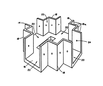
comprises a construction device 14, Figures 1-8, which may be molded, stamped, or
otherwise formed from a tough plastic or metal. The body member of the device 14includes a flat bottom wall 16 and four identically shaped or symmetrical upright
quarter sections 18. Each of the sections 18 comprises four zig zag panels 1 8a joined
integrally at right angles. These symmetrical quarter sections are shaped to form a
recess or opening 20 on each side, with oppositely located recesses being laterally
aligned. Also, with this quarter section construction, a square central socket 22 is
formed. Laterally aligned recesses 20 provide a full width slot open at the sides.
Each of the panel sections 1 8a has one or more apertures 24 therein provided
to receive fasteners, to be seen hereinafter, for securement of building elements to the
device 14. As seen in Figure 2, cutouts 26 are provided in the bottom wall 16 for
reducing the weight of the member as well as for conserving material. Also, apertures
X
1 338371
28 are provided in the wall 16 for secured attachment of the member 14 to a base,
such as to a block 10, concrete slab, or other support means.
Figures 5, 6, 7 and 8 show various applications of the construction device 14
with building elements such as beams and pillars. Figure 5 for example shows a floor
5 beam or joist 30 seated edgewise on the bottom wall 16 and extending fully through
the device and out both side recesses 20. Figure 6 shows a beam 30 similarly
supported as in Figure 5 but also showing a right angle beam 32 extending through a
90 degree side recess 20 and abutted against the beam 30. Figure 7 shows a vertical
pillar 34 supported on the device 14 and fitted in the central socket 22. Figure 8
shows a pillar 34 similarly fitted in the socket 22 in Figure 7 but also showing side
beams 32 extending in from all four of the side recesses. These members may simply
be fitted in the respective recesses 20 or socket 22 but in most cases secured
attachment to the member 14 is accomplished by fasteners 36 extending through the
apertures 24. Also, device 14 can first be secured to the base member by fasteners
15 extending through the apertures 28.
Figure 3 is a bottom perspective view of a construction device 14' having a
bottom wall 16 and side walls 18 in an arrangement similar to that shown in Figures 1
and 2. This structure, however, is formed, such as by integral molding, with a
plurality of depending foot members 38. Four of such foot members are shown, as
20 well as a central foot member, but any number of such foot members may be
provided. In the Figure 3 embodiment, the foot members 38 are hollow whereby long
fasteners can be inserted down from the top through the wall 16 and into a base for
secured attachment of the construction device 14' to the base. Figure 4 shows a
1 338371
structure similar to Figure 3 except that the outer foot members 38' are solid and not
hollow. This embodiment may be employed in circumstances where it is not
necessary to use vertical fasteners around an outer portion of the member.
Figures 9-12 illustrate an embodiment of the invention employing means for
5 anchoring the body member against lateral shifting. In this embodiment, the body
member 14" is the same as that shown in Figure 1 as to quarter panel sections 18a and
their formation of aligned recesses 20 and central socket 22. To accomplish the lateral
anchoring feature of the outermost panel section 18a of each quarter section has a
depending projection or lip 40 defined by a bottom wall portion 42 integral with side
extensions 44 and a rear wall portion 46. Rear wall portion 46 preferably angles
outwardly toward the bottom whereby to coincide with the angle of the side surfaces
of a pier block 10 of the type shown in Figures 5-8. Wall portion 46 can extend at the
desired angle, so as to have flush engagement with the pier block sides.
Figures 11 and 12 show application of the device 14" of Figure 9 to a pier
block. In such arrangements, the device and the building elements therein are
anchored or locked against lateral shifting. Fasteners extending through the bottom
wall of the device are not necessary, although such fasteners can be used if desired.
The cross dimension of the device between wall portions 14" can be preselected
according to the size of the pier block to that a snug or frictional fit is provided.
With reference to Figures 13, 14 and 15, the concept of the invention ~ltili~ing
side recesses or openings 20' for receiving floor beams 30 and the central socket 22'
for receiving vertical pillars 34 can be applied to a concrete block structure 40 by
molding such openings and socket in the top of the block. With reference to Figures
1 338371
14 and 15, this structure is similar in use to the construction device 14 of Figure 1 to
the extent that it can receive a floor beam 30 thereacross in one direction, Figure 14,
or as shown in Figure 15 a vertical pillar 34, and if desired two side beams abutted
against the pillar.
According to the present invention, a construction device is provided which
conveniently provides lateral anchoring of a building element to a base. The
embodiment of Figures 1 and 2 further provides secured attachment, by means of the
fastening holes 24 and 28 of a building element to a base. The device of Figure 1 can
be inexpensively molded from plastic or stamped from metal and is simplified in its
use and construction. The device of Figure 13 can also be inexpensively poured from
concrete with suitably shaped forms. The invention although embodied in a singledevice allows a variety of combinations and connections for building elements. The
dimensions may vary and be selective to provide desired fittings of conventionalbuilding elements.
It is to be understood that the forms of our invention herein shown and
described are to be taken as preferred examples of the same and that other changes in
the shape, size and arrangement of parts may be resorted to without departing from the
spirit of my invention or the scope of the subjoined claims.
Having thus described our invention, We claim:
X