Language selection

Search

Patent 1339157 Summary

Third-party information liability

Some of the information on this Web page has been provided by external sources. The Government of Canada is not responsible for the accuracy, reliability or currency of the information supplied by external sources. Users wishing to rely upon this information should consult directly with the source of the information. Content provided by external sources is not subject to official languages, privacy and accessibility requirements.

Claims and Abstract availability

Any discrepancies in the text and image of the Claims and Abstract are due to differing posting times. Text of the Claims and Abstract are posted:

  • At the time the application is open to public inspection;
  • At the time of issue of the patent (grant).
(12) Patent: (11) CA 1339157
(21) Application Number: 615508
(54) English Title: CONNECTION OF SUBSCRIBER COMMUNICATION NETWORK BASE STATION TO EXTERNAL INFORMATION NETWORK
(54) French Title: CONNEXION A UN RESEAU D'INFORMATION EXTERNE DE LA STATION DE BASE D'UN RESEAU DE COMMUNICATION A ABONNES
Status: Expired
Bibliographic Data
(52) Canadian Patent Classification (CPC):
  • 344/25
(51) International Patent Classification (IPC):
  • H04W 88/08 (2009.01)
  • H04W 28/14 (2009.01)
  • H04W 72/04 (2009.01)
  • H04W 74/04 (2009.01)
  • H04W 92/02 (2009.01)
  • H04Q 7/22 (2006.01)
(72) Inventors :
  • AVIS, GRAHAM M. (United States of America)
  • COLLINS, TERRANCE STEPHEN (United States of America)
  • SCHROEDER, MARTIN KEITH (United States of America)
  • KIERNAN, BRIAN GREGORY (United States of America)
  • MECHLING, JONATHAN WILLIS (United States of America)
(73) Owners :
  • INTERDIGITAL TECHNOLOGY CORPORATION (United States of America)
(71) Applicants :
  • INTERNATIONAL MOBILE MACHINES CORPORATION (United States of America)
(74) Agent: RIDOUT & MAYBEE LLP
(74) Associate agent:
(45) Issued: 1997-07-29
(22) Filed Date: 1988-03-28
Availability of licence: N/A
(25) Language of filing: English

Patent Cooperation Treaty (PCT): No

(30) Application Priority Data: None

Abstracts

English Abstract


A base station in a subscriber communication network for
communicating signals between subscriber stations and an external
communication network having a plurality of ports. The base station
includes a communication circuit for enabling simultaneous
communications between a plurality of the ports and a plurality of
subscriber stations over a given communication channel having multiple
sequentially repetitive time slots, with predetermined time slots being
assigned respectively to predetermined subscribers stations; a
remote-connection processor for directing communications between the time slot
assigned to a given subscriber station and a given external
communication network port; and an exchange for connecting the
communication circuit to the external communication network ports. The
exchange includes a central concentrator for directing signals from
predetermined external network ports to predetermined sequentially
repetitive time slots in a bit stream generated by the central
concentrator, and for directing signals to predetermined external
network ports from predetermined sequentially repetitive time slots in a


bit stream received by the central concentrator; and the
remote-connection processor directs signal transfer between given sequentially
repetitive time slots of the bit streams and given sequentially
repetitive time slots of the communication channel. The
remote-connection processor includes a remote concentrator for directing
signals from predetermined remote ports to predetermined sequentially
repetitive time slots in a bit stream generated by the remote
concentrator and transmitted to the central concentrator, and for
directing signals to predetermined remote ports from predetermined
sequentially repetitive time slots in the bit stream generated by the
central concentrator; and a buffer unit connected to the remote ports
for directing signals between predetermined remote ports and
predetermined communication channel time slots. The exchange may be
located remotely from the communication circuit; and the bitstream may
be transmitted between the exchange and the communication circuit by
microwave.


French Abstract

Station de base dans un réseau de communication à abonnés, communiquant des signaux entre des stations d'abonnés et un réseau de communication externe ayant une pluralité de ports. La station de base comprend un circuit de communication autorisant des communications simultanées entre une pluralité des ports et une pluralité de stations d'abonnés sur un canal de communication donné ayant de multiples créneaux temporels itératifs séquentiels, des créneaux temporels prédéterminés étant attribués respectivement à des stations d'abonnés prédéterminées ; un processeur de connexion à distance dirigeant les communications entre le créneau temporel attribué à une station d'abonné donnée et un port de réseau de communication externe donné ; et un échangeur reliant le circuit de communication aux ports de réseau de communication externe. L'échangeur comprend un concentrateur central dirigeant des signaux de ports de réseau externe prédéterminés vers des créneaux temporels itératifs séquentiels prédéterminés, dans un flux binaire généré par le concentrateur central, et dirigeant des signaux vers des ports de réseau externe prédéterminés en provenance de créneaux temporels itératifs séquentiels prédéterminés, dans un flux binaire reçu par le concentrateur central ; et le processeur de connexion à distance dirige un transfert de signal entre des créneaux temporels itératifs séquentiels donnés des flux binaires et des créneaux temporels itératifs séquentiels donnés du canal de communication. Le processeur de connexion à distance comprend un concentrateur à distance dirigeant des signaux de ports à distance prédéterminés vers des créneaux temporels itératifs séquentiels prédéterminés, dans un flux binaire généré par le concentrateur à distance et transmis au concentrateur central, et dirigeant des signaux vers des ports à distance prédéterminés en provenance de créneaux temporels itératifs séquentiels prédéterminés, dans le flux binaire généré par le concentrateur central ; et une unité de tampon reliée aux ports à distance dirigeant des signaux entre des ports à distance prédéterminés et des créneaux temporels de canal de communication prédéterminés. L'échangeur peut se trouver à distance du circuit de communication ; et le flux binaire peut être transmis entre l'échangeur et le circuit de communication par micro-ondes.

Claims

Note: Claims are shown in the official language in which they were submitted.


THE EMBODIMENTS OF THE INVENTION IN WHICH AN EXCLUSIVE PROPERTY
OR PRIVILEGE IS CLAIMED ARE DEFINED AS FOLLOWS:

1. An apparatus for communicating between subscriber
stations and an external network; comprising
a central terminal in communication with said
external communication network,
a processor in said central terminal
communicating with a communication terminal for
directing communications between said central terminal
and said communication terminal;
a plurality of channel modules in said
communication terminal in communication with a greater
plurality of subscriber stations via RF communication
frequencies having multiple time slots, time slots
being assigned to subscriber stations as needed;
at least one controller in said communication
terminal for directing communications between the
channel modules and the central terminal wherein,
said central terminal and said communication
terminal are in communication with each other via bit
streams generated and received by each, bit streams
transmitted by said central terminal to said
communication terminal containing signals initiated
from said external network and bit streams transmitted
by said communication terminal to said central


-22-


terminal containing signals initiated from said
subscriber stations, said bit streams containing
multiple sequentially repetitive time slots; and
a control channel (BCC) between said central
terminal and said communication terminal for
transmitting control signals which can be initiated by
both terminals.

2. An apparatus according to claim 1, wherein said
controller is connected to the channel modules over a path
carrying a plurality of channels and acts to interface with
said channel modules for directing signals between time
slots in said RF communication frequencies and channels on
said path.


3. An apparatus according to claim 1, wherein at least one
of said terminals includes a concentrator.


4. An apparatus according to claim 1, wherein the central
terminal is remotely located from the communication
terminal.


5. An apparatus for communication between subscriber
stations and an external communication network having a
plurality of ports, comprising


-23-


at least one trunk for providing a communication
channel between an exchange and a terminal, said
terminal having at least one controller;
said controller being coupled to a plurality of
channel modules and providing multiple sequentially
repetitive time slots in RF channels, the time slots
being assigned to subscriber stations in accordance
with a predetermined assignment routine in response to
an incoming call or call request, thereby enabling
concurrent communications from the plurality of ports
to be applied to subscriber stations;
the exchange connecting the trunk to the external
communication network ports; wherein
a processor is coupled to the exchange by a base
station control channel for causing the exchange to
complete a connection between a given external
communication network port and the controller by means
of a time slot on the communication channel;
the plurality of channel modules coupling the
communication signals to given subscriber stations via
the radio frequency (RF) channels;
the channel modules are respectively coupled by
the controller to time slots of the communication
channel carried over the trunk and to assigned time
slots of the radio frequency channels.


-24-


6. An apparatus according to claim 5, wherein the exchange
comprises a concentrator.


7. An apparatus according to claim 5, further comprising
control means to decrease jitter and to control slips in
the received signals.


8. An apparatus as in claim 7, further comprising a frame
buffer containing a plurality of frames, wherein
a selected address within each frame corresponds
to a selected channel assignment, said frames having
an initial predetermined separation.


9. An apparatus according to claim 5, further comprising
an echo canceller for cancelling echoes in voice
signals communicated over the trunk; wherein
the processor is coupled to the echo canceller for
enabling the operation of the echo canceller during
only those time slots that have been assigned by the
processor to carry voice signals.

10. An apparatus as in claim 5, wherein
each channel module couples a plurality of RF
time slots to a corresponding plurality of subscriber
stations according to an allocation routine; and


-25-


wherein said allocation routine includes
allocating all of the RF time slots associated
with a given channel module before allocating time
slots associated with another channel module.


11. An apparatus as in claim 5, and further comprising a
control channel between the exchange and the communication
terminal for transmitting control signals therebetween.


12. An apparatus as in claim 6, wherein
a communication signal processor is coupled to
given subscriber stations by the channel module in
response to command signals from the processor, said
processor sending said command signal in response to
an incoming call or call request and is respectively
coupled by the controller to predetermined time slots.


13. An apparatus as in claim 12, wherein
the communication signal processor provides a
predetermined signal pattern in its predetermined time
slot when not coupled by its channel module to its
subscriber station, and wherein
the exchange is responsive to a command
from the processor causing a signal received by the
exchange from one of the communication signal
processors over a given time slot to be looped back to
the communication signal processor coupled to that
time slot; and wherein


-26-


the communication signal processor is coupled to
the channel module for enabling the channel module to
receive commands from the processors in response to a
said looped-back predetermined signal pattern for
assigning the communication signal processor to
communicate with a given subscriber station.


14. An apparatus according to claim 13, wherein
the processor comprises means for assigning a
given time slot to a given subscriber station, said
assigning means including
means for commanding the exchange to loop back
signals received from the communication signal
processor coupled to the given time slot;
means for sending an address initialization signal
over the control channel to all of the channel modules
to store in address associated with the given
subscriber station in the channel module that is
enabled in response to the communication signal
processor coupled thereto receiving said looped-back
predetermined signal pattern; and
means for commanding the channel module in which
the address is stored to assign the given time slot
coupled communication signal processor to the given
subscriber station.


-27-


15. An apparatus according to claim 14, wherein
each channel module includes means for responding
to storage of said address by sending an
acknowledgement to the processor; and wherein
the processor further includes means for
commanding the exchange to loop back signals received
from the communication signal processor coupled to a
different given time slot when no acknowledgement is
received from the channel module coupled to the
communication signal processor coupled to the first
recited given time slot.


16. An apparatus in claim 5, wherein
in response to the central channel the channel
module communicates control signals to a subscriber
station over a radio control channel allocated to a
given RF time slot of a given frequency channel by the
processor.


17. An apparatus according to claim 5, wherein
the controller and the channel modules are modular
for enabling their addition to and removal from the
system in accordance with changes in the number of
subscriber stations with which the base station
communicates.


-28-


18. An apparatus according to claim 5, wherein said
exchange is remotely located from the terminal.


-29-

Description

Note: Descriptions are shown in the official language in which they were submitted.


1339157


CONNECTION OF SUBSCRIBER COMMUNICATION NETWORK
BASE STATION TO EXTERNAL INFORMATION NETWORK


BACKGROUND OF THE INVENTION
The present invention generally pertains to communications
systems and is particularly directed to an improvement in connecting a
subscriber communication network base station to an external
communication network having a plurality of ports.

A known prior art base station in a subscriber communication
network for communicating signals between subscriber stations and an
lo external co~munication network having a plurality of ports, includes a
communication circuit for enabling simultaneous communications between a
plurality of the ports and a plurality of subscriber stations over a
given communication channel having multiple sequentially repetitive time
slots, with predeternined time slots being assigned respectively to
predetermined subscriber stations; a remote-connection processor for
directing communications between the time slot assigned to a given
subscriber station and a given port; and an exchange for connecting the
communication circuit to the ports. The exchange includes a switch

*

1339157

which responds to a control signal from the remote-
connection processor by physically connecting a selected
port to a selected communication channel time slot assigned
to a given subscriber station. Such a prior art base
station is described in United States Patent No. 4,675,863,
E. Paneth et al, issued on June 23, 1987.


SUMMARY OF THE INVENTION
The present invention provides an improved base
station of the type generally described above, except that
the exchange does not include such a switch. The base
station of the present invention is characterized by the
exchange including a central concentrator for directing
signals from predetermined external network ports to
predetermined sequentially repetitive time slots in a bit
stream generated by the central concentrator, and for
directing signals to predetermined external network ports
from predetermined sequentially repetitive time slots in a
bit stream received by the central concentrator; and by the
remote-connection processor directing signal transfer
between given sequentially repetitive time slots of the bit
streams and given sequentially repetitive time slots of the
communication channel.


~ 3391~7


The base station of the present invention is further
characterized by the remote-connection processor comprising a remote
terminal concentrator for directing signals from predetermined remote
ports to predetermined sequentially repetitive time slots in a bit
stream generated by the remote concentrator and transmitted to the
central concentrator, and for directing signals to predetermined remote
ports from predetermined sequentially repetitive time slots in the bit
stream generated~ by the central concentrator; and a buffer unit
connected to the remote ports for directing signals between
predetermined remote ports and predetermined communication channel time
slots.

Because the exchange of the base station of the present
invention co~m~lnicates with the cammunication circuit by generating and
receiving bitstreams as described above, it is practical to locate the
lS exchange of the base station of the present invention remotely from the
communication circuit of the base station since the bitstream may be
transmitted between the exchange and the communication circuit over
appreciable distances by microwave.

Additional features of the present invention are described with
reference to the description of the preferred embodiment.

13391~7


BRIEF DESCRIPTION OF THE DRAWING

Figure 1 is a block diagram of a preferred embodiment of the
base station of the present invention.

Figure 2 is a block diagram of a buffer unit included in the
S buffer of the base station of Figure 1 for interfacing with a single
channel module.

Figure 3 is a state diagram illustrating normal call processing
flow in the base station of Figure 1.

DESCRIPTION OF THE PREFERRED EMBODIMENT

The preferred embodiment of the base station of the present
invention is used in a subscriber telephone system.

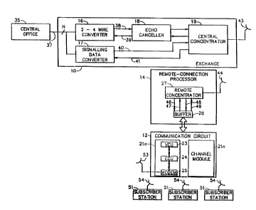
Referring to Figure 1, a preferred embodiment of the base
station of the present invention includes an exchange 10, a
communication circuit 12 and a remote-connection processor 14. The

1339157


communication circuit 12 and the remote control processor 14 are located
remotely from the exchange 10.


The exchange lO includes a two-to-four wire converter 16, a
signalling data converter 17, an echo canceller 18, and a central
5concentrator 19. The communication circuit 12 includes a plurality of
channel modules 21a, ..., 21n. Each channel module 21 includes a voice
codec unit (VCU) 23, a channel control unit (CCU) 24 and a modem 25.
The remote-connection processor 14 includes a remote concentrator 27 and
a buffer unit 28.


loReferring to Figure 2, the buffer unit 28 includes a timing
generator 30 and a channel interface module 32.


Referring again to Figure 1, the exchange 10 is connected to a
plurality of ports of a central office 35 by N pairs of lines 37. "N"
is the number of subscriber stations being served by the base station.
15Each pair of lines 37 provides a 2-wire loop appearance. Each line pair
37 is connected to both the two-to-four wire converter 16, and the
sign~lt~ng data converter 17. Unidirectional signal flow takes place on
the line pairs 38-41 on the other sides of the converters 16, 17, with
4-wire loop appearances being provided on the combination of N line

1339157


pairs 38 and N line pairs 39. Transmitted voice signals are provided on
line pairs 38; recieved voice signals are provided on line pairs 39;
transmitted sign~ ng data is provided on line pairs 40; and received
signalling data is provided on line pairs 41.

The transmitted and received voice signals are CQ' lln~cated
between the two-to-four wire converter 16 and the central concentrator
19 through the echo canceller 18. The sign~lling data is communicated
directely between the converter 17 and the central concentrator 19.

The central concentrator 19 is a Model 1218C concentrator sold
by ITT Corp.

The central concentrator 19 directs signals from predetermined
line pairs 38-41 (which are connected to predetermined external network
ports in the central office 35) to predetermined sequentially repetitive
time slots in a bit stream generated by the central concentrator 19.
The central concentrator 19 also directs signals to predetermined
external network ports in the central office via predetermined line
pairs 38-41 from predetermined sequentially repetitive time slots in a
bit stream recieved by the central concentrator 19. The central
concentrator transmits and receives such bit streams via a microwave
antenna 43.

1339157


These bit streams are communicated between the antenna 43 and a
microwave antenna 44 connected to the remote concentrator 27 contained
in the remote-connection processor 14. The remote concentrator 27 has a
plurality of remote ports connected to the buffer 28 by line pairs
46-49.

The remote concentrator 27 is a Model 1218S concentrator sold by
rTT Corp.

The remote concentrator 27 directs signals from predetermined
remote terminals (which are connected to predetermined line pairs 46-49)
lo to predetermined sequentially repetitive time slots in a bit stream
generated by the remote concentrator 27. The remote concentrator 27
also directs signals to predetermined remote ports from predetermined
sequentially repetitive time slots in the bit stream recieved by the
remote concentrator 27 from the central concentrator 19.

The transmitted voice signals are provided on line pairs 46; the
recieved voice signals are provided on line pairs 47; the transmitted
sign~lling data is provided on line pairs 48; and the recieved
signalling data is provided on the line pairs 49.

1339157


The buffer 28 interfaces the remote concentrator 27 with the
communication circuit 12.

As described above, the communication circuit 12 include,s a
plurality of channel modules 21. Each channel module 21 commlnicates
with a given number of subscriber stations 51 over a given communication
channel having an assigned frequency and further having multiple
sequentially repetitive time slots. Communication between each channel
module 21 and the base stations 51 is via a microwave link between a
base station antenna 53 and antennas 54 located at each subscriber
station. Predetermined time slots are assigned to predetermined
subscriber stations 51. In the preferred embodiment, there are three
subscriber stations 51 coupled to each channel module 19 over each
discrete frequency communication channel. Each subscriber station 51
has a telephone connected thereto.

In each ~h~nn~l module 21, the VCU 23 includes a separate voice
codec (not shown~ for each subscriber station 51 and an additional codec
for comm~lnicating signalling data to and from all three subscriber
stations. The CCU 24 assigns the signals communicated through the
codecs of the VCU 23 to different time slots of the communication
r,h~nnPl assigned to the given channel module 21. These signals are

1339157


communicated between the CCU 24 and the base station antenna 53 via the
modem 25 and additional signal conditioning components (not shown)
adapted for transmitting and recieving these signals over the discrete
communication ch~nnel at the assigned frequency. Thus, each subscriber
station ~1 communicates voice signals with the base station over its own
predetermined time slot and communicates signalling data with the base
station over a predetermined time slot that is common to all three
subscriber stations. Com~nication between the base station and the
subscriber stations is controlled by a radio control unit (RCU) software
process implemented by a microcomputer in the CCU 24.


The RCU is programmed to recognize three predetermined
subscriber stations corresponding to three predetermined line
appearances provided by the connections between the remote concentrator
27 and a given channel module 21.


lS Control processing in the RCU is organized using state machines.
Input message tokens include sign~1ling data from the remote
concentrator 27, radio control channel (RCC) messages from the
subscriber stations, and (simulated) baseband control channel (BCC)
messages.

1339I57

The state diagram, Fig. 3, illustrates the normal
call processing states and the input token (T) and the
resulting action (A) required to transit from one state to
another. The following descriptions outline some of the
state transition routines. Other routines, such as those
required for error handling, have not been described.

The following group of descriptions define some
of the RCC state transition routines which are called
whenever a RCC token is received by a CCU, whether from a
subscriber station or the remote concentrator.

Clear Call (cl call)
Current State: Active, Teardown
Token: Clear Request
Next State (RCC): RCC Idle


~-O

1339157
Next State (CHAN): Chnl Idle
Messages:
Conc: Place circuit in idle state.
RCC: None.
CCU: Change channel (onhook) is sent to the CCU.
Actions:


This routine is invoked whenever a subscriber station
generates a Clear Request. The channel state is set to
Chnl Idle. The clear-request timer is cancelled. Whether
or not teardown was in progress, the RCU considers the
subscriber station available for another call, and returns
the RCC state to RCC Idle.


1339157

Place Call Origination (place)
Current State: RCC Idle
Token: Call Request


i339157


Next State (RCC): Active
Next State (CHAN): Offhk Syn Wait
Messages:
Conc: Place circuit in loop state.
RCC: Send Call Connect message to Subscriber Station.
CCU: Send Change Channel (OFFHOOK).
Actions:

This routine is invoked when a Subscriber Station is in the RCC
Idle state and the RCU receives a Call Request token. A Change Channel
message with an Offhook status is sent to the CCU, and a Call Connect
message is sent to the Subscriber Station. The channel state of the
allocated frequency is set to Offhk Syn Wait, and the RCC state is set
to Active.
- Subscriber Stati~n Call Accept (s accp)
Current State: Page
Token: Call Accept
Next State (RCC): Active
Next State (CHAN): Ring Syn Wait
Messages:

1339157

Conc: Place circuit in loop state.
RCC: Send Call Connect message.
CCU: Send Change Channel (RING).
Actions:


This routine is invoked when the RCU receives a Call
Accept token from a Subscriber Station that is in the Page
state. The page timer is cancelled. A Change Channel
message with Ring status is sent to the CCU, and a Call
connect message is sent to the Subscriber Station. The
channel state is set to Ring Syn Wait, and the RCC state is
set to Active.


l339l57

Subscriber Station Page (s_page)
Current State: RCC Idle


l339l57
Token: Incoming Ring
Next State (RCC): Page
Next State (CHAN): No state change
Messages:
Conc: None.
RCC: Send a Page message if the Subscriber Station.
CCU: None
Actions:

If an Incoming Ring token is received from the
concentrator while the Subscriber Station is in the RCC
Idle state, then this routine is invoked. The line
appearance is mapped to a predetermined Page message, which
is then transmitted to the appropriate Subscriber Station.
A timer is set in case the Subscriber Station does not
respond to the page. The RCC state is set to Page.


The following group of descriptions define some of the
channel state transition routines which are called whenever
a token is received from a CCU.


16

1339ls7


Subscriber Station Ring Trip (rng_offhk)
Current State: Syn Ring, Ring Syn Wait
Token: Sync Offhook
Next State (RCC): No state change
Next State (CHAN): Syn Offhk
Messages:
Conc: None.
RCC: None.
CCU: Send Change Channel (OFFHOOK) to the CCU.
Actions:


This routine is activated when a Subscriber Station is
in the ring state and either in or out of synchronization,
and the RCU receives


13~9157


a message that the Subscriber Station is now in synchronization and has
transitioned to Offhook. Normally, when a Sync Offhook token is
received, the Subscriber Station is already in synchronization. The CCU
is sent a Change Channel message with Offhook status, and the channel
state is changed to Syn Offhk.
Subscriber Station Sync Offhook (syn offhk)
Current State: Offhk Syn Wait
Token: Sync Offhook
Next State (RCC): No state change
lo Next State (CHAN): Syn Offhk
Messages:
Conc: None.
RCC: None.
CCU: None.
Actions:

This routine generates no messages, it only causes a change in
channel state to Sync Offhk.
Subscriber Station Sync Ring (syn ring)
Current State: Ring Syn Wait

Token: Sync Ring


13391~7


Next State (RCC): No state change
Next State (CHAN): Syn Ring
Messages:
Conc: None.
RCC: None.
CCU: None.
Actions:

This routine changes the channel state to Syn Ring.

The buffer 28 is connected to the remote ports of the remote
lo concentrator 27 via line pairs 46-49 and to the ~h~nnel modules 21 of
the communication circuit 14 via lines 57 for directing the transmitted
and recieved voice signals between the predetermined remote ports of the
remote concentrator 27 and the predetermined communication channel time
slots assigned to predetermined subscriber stations 51. The subscriber
stations 51 are located remotely from the base station.

The buffer 28 includes a separate buffer unit, as shown in
Figure 2, for interfacing with each channel module 21 in the
communication circuit 12. The timing generator 30 provides the channel

1339157


interface module 32 with a clock signal CLK and four gate signals Gate
0, Cate 1, Gate 2, Gate 3 for defining four sequentially repetitive time
slots in the assigned communication ch~nnel.


The transmitted voice signal line pairs 46, the received voice
signal line pairs 47, and the the signalling data line pairs 48, 49 are
connected between the remote ports of the concentrator 27 and the
channel interface module 32.


The channel interface module 32 provides the clock and gate
signals to the channel module 27 for defining the time slots assigned by

the CCU 24.


The channel interface module 32 is connected to the VCU 23 in
the corresponding channel module 21 in a predetermined manner for
directing communications between line pairs 46, 47 carrying transmitted
and received voice signals associated with a given subscriber station

and a codec in the VCU 23 having the predetermined communication channel
time slot assigned by the CCU 24 to the given subscriber station. The
channel interface module is further connected to the VCU 23 for
directing the signalling data between the signalling data line pairs 48,
49 and the the voice codec in the VCU having the common time slot


~,o

1339157


assigned by the CCU 24 for communicating signalling data ~or all three
subscriber stations associated with the given channel module.


~l

Representative Drawing
A single figure which represents the drawing illustrating the invention.
Administrative Status

For a clearer understanding of the status of the application/patent presented on this page, the site Disclaimer , as well as the definitions for Patent , Administrative Status , Maintenance Fee  and Payment History  should be consulted.

Administrative Status

Title Date
Forecasted Issue Date 1997-07-29
(22) Filed 1988-03-28
(45) Issued 1997-07-29
Expired 2014-07-29

Abandonment History

There is no abandonment history.

Payment History

Fee Type Anniversary Year Due Date Amount Paid Paid Date
Application Fee $0.00 1988-03-28
Registration of a document - section 124 $0.00 1999-04-14
Registration of a document - section 124 $0.00 1999-04-28
Maintenance Fee - Patent - Old Act 2 1999-07-29 $300.00 1999-09-20
Maintenance Fee - Patent - Old Act 3 2000-07-31 $100.00 2000-06-19
Maintenance Fee - Patent - Old Act 4 2001-07-30 $100.00 2001-06-18
Maintenance Fee - Patent - Old Act 5 2002-07-29 $150.00 2002-06-17
Maintenance Fee - Patent - Old Act 6 2003-07-29 $150.00 2003-06-19
Maintenance Fee - Patent - Old Act 7 2004-07-29 $200.00 2004-06-16
Maintenance Fee - Patent - Old Act 8 2005-07-29 $200.00 2005-06-07
Maintenance Fee - Patent - Old Act 9 2006-07-31 $200.00 2006-06-07
Maintenance Fee - Patent - Old Act 10 2007-07-30 $250.00 2007-06-07
Maintenance Fee - Patent - Old Act 11 2008-07-29 $250.00 2008-06-10
Maintenance Fee - Patent - Old Act 12 2009-07-29 $250.00 2009-06-19
Maintenance Fee - Patent - Old Act 13 2010-07-29 $250.00 2010-06-17
Maintenance Fee - Patent - Old Act 14 2011-07-29 $250.00 2011-06-08
Maintenance Fee - Patent - Old Act 15 2012-07-30 $450.00 2012-06-14
Maintenance Fee - Patent - Old Act 16 2013-07-29 $450.00 2013-06-12
Owners on Record

Note: Records showing the ownership history in alphabetical order.

Current Owners on Record
INTERDIGITAL TECHNOLOGY CORPORATION
Past Owners on Record
AVIS, GRAHAM M.
COLLINS, TERRANCE STEPHEN
INTERDIGITAL COMMUNICATIONS CORPORATION
INTERNATIONAL MOBILE MACHINES CORPORATION
KIERNAN, BRIAN GREGORY
M/A-COM GOVERNMENT SYSTEMS, INC.
MECHLING, JONATHAN WILLIS
SCHROEDER, MARTIN KEITH
Past Owners that do not appear in the "Owners on Record" listing will appear in other documentation within the application.
Documents

To view selected files, please enter reCAPTCHA code :


To view images, click a link in the Document Description column. To download the documents, select one or more checkboxes in the first column and then click the "Download Selected in PDF format (Zip Archive)" or the "Download Selected as Single PDF" button.

List of published and non-published patent-specific documents on the CPD .

If you have any difficulty accessing content, you can call the Client Service Centre at 1-866-997-1936 or send them an e-mail at CIPO Client Service Centre.


Document
Description 
Date
(yyyy-mm-dd) 
Number of pages   Size of Image (KB) 
Representative Drawing 2001-12-11 1 10
PCT Correspondence 1995-11-15 1 50
Office Letter 1997-04-22 1 63
PCT Correspondence 1996-10-28 3 89
Examiner Requisition 1993-12-09 2 96
Examiner Requisition 1990-04-30 1 40
Examiner Requisition 1996-07-26 2 68
Examiner Requisition 1996-11-22 1 67
Prosecution Correspondence 1990-07-30 2 63
Prosecution Correspondence 1994-03-09 2 75
Prosecution Correspondence 1995-11-15 2 56
Prosecution Correspondence 1997-01-27 5 227
Prosecution Correspondence 1995-03-15 1 26
Cover Page 1997-12-08 1 19
Abstract 1997-06-02 2 59
Description 1997-06-02 21 415
Claims 1997-06-02 8 204
Drawings 1997-06-02 2 40
Fees 1999-09-20 1 33