Note: Descriptions are shown in the official language in which they were submitted.
1~9586
METHOD A~D APPARATUS ~OR
CORRECTING VIDEO CO~R SIGNALS
This invention relates to correcting video color
6ignals and, more part$cularly, to a method and
apparatus for preci6ely isolating video color signals
for selective color correction.
In video color recording, the images are
represented by either of two sets of signals. One
signal set is red/green/blue. The other signal set is
luminance lY) and color difference, i.e. red minus
luminance (R-Y) and blue minus lum~nA~ce (B-Y).
In the cour~e of production of television and
video color recordings, lt i8 sometimes desirable to
correct 6electively the colors of the subject images.
Many years ago Mon~An et al. disclosed a non-linear
matrixing device for color correction in U.S. Patent
No. 3,558,806. This matrixing device operates upon
the red/green/blue signals to permit independent
adjustment of the hue and saturation of the three
primary colors, red, green, and blue, and the
secondary colors, cyan, yellow, and magenta. When an
object made up of more than one color is to be color
corrected, a coordinated adjustment of both colors is
required.
2 1~ 39~86
Recently, Korman disclosed in U.S. Patent No.
4,525,736 color modification apparatus which operates
upon the color difference signals known as I and Q,
rather than the primary and secondary color signals. The
color signals to be corrected are selected by limit
circuits which determine when the difference signals lie
between prescribed boundaries in the chrominance plane.
These boundaries define rectangular regions in the
chrominance plane which do not correspond to the polar
coordinate color corrections actually made by the
colorist. As a result, the colorist may encounter
difficulty in selecting the signals to be color
corrected.
According to a first aspect the invention is a color
correction system for manipulating color signals
comprising hues capable of being represented by an angle
in polar coordinates in a chrominance plane, the system
comprising:
means for receiving video color component difference
signals at an input;
means for transmitting correction video color
component difference signals from an output;
means coupled between the receiving means and the
transmitting means and responsive to a first input signal
for defining a hue angle representing a hue signal to be
passed from the receiving means to the transmitting
means;
means coupled between the angle defining means and
the transmitting means for defining a hue sector
containing the hue angle and representing hue boundaries
outside of which hue signals representing hues outside of
the hue sector are not passed to the transmitting means;
wherein the hue angle defining means comprises a
matrixing circuit for producing signals representing
color difference signals; and
wherein the hue angle defining means further
comprises means coupled to the matrixing circuit for
.~,
1~39~8~
producing separate signals representing at least three
hues.
According to a further aspect the invention is a
color correction system for manipulating color signals
comprising hues capable of being represented by an angle
in polar coordinates in a chrominance plane, the system
comprising;
means for receiving video color component difference
signals at an input;
means for transmitting correction video color
component difference signals from an output;
means coupled between the receiving means and the
transmitting means and responsive to a first input signal
for defining a hue angle representing a hue signal to be
passed from the receiving means to the transmitting
means;
means coupled between the angle defining means and
the transmitting means for defining a hue sector
containing the hue angle and representing hue boundaries
outside of which hue signals representing hues outside of
the hue sector are not passed to the transmitting means;
wherein the hue sector defining means comprises
means responsive to a second input signal for changing
the hue boundaries relative to the hue angle; and
wherein the hue angle defining means comprises a
matrixing circuit for producing signals representing
color difference signals and wherein the hue angle
defining means further comprises means coupled to the
matrixing circuit for producing separate signals
representing at least three hues and wherein the means
for producing separate signals representing at least
three hues comprises first, second and third output
circuits, the first and third being coupled to a non-
additive mixer having an output coupled to means formaintaining a gain of the output of the non-additive
mixer.
According to a further aspect the invention is a
color correction system for manipulating color signals
~3g-~86
2b
comprising hues capable of being represented by an angle
in polar coordinates in a chrominance plane, the system
comprlslng:
means for receiving video color component difference
signals at an input;
means for transmitting correction video color
component difference signals from an output;
means coupled between the receiving means and the
transmitting means and responsive to a first input signal
for defining a hue angle representing a color component
difference signal to be passed from the receiving means
to the transmitting means;
means coupled between the angle defining means and
the transmitting means for defining a hue sector
containing the hue angle and representing hue boundaries
outside of which color component difference signals
representing hues outside of the hue sector are not
passed to the transmitting means;
a color input matrix for accepting color video input
signals and producing color component difference signals
to the means for receiving video color component
difference signals; and
at least one summing circuit having a first input
coupled to the means for transmitting corrected video
color component difference signals and a second input
coupled to an output from the color input matrix for
accepting an uncorrected video color component difference
signal from the color input matrix.
According to a further aspect the invention is a
color correction system comprising:
means for transmitting from an input to an output
video component color difference signals which only lie
within an adjustably fixed hue sector;
a source of video component color signals to be
corrected;
means responsive to a first control signal for
rotating the difference signals from the source to an
13~86
2c
angle which corresponds to the fixed hue sector in which
the difference signals are to be corrected;
means for applying the rotated difference signals to
the input to produce at the output an isolated color
signal only when at least part of the difference signals
lie within the fixed hue sector;
means responsive to a second control signal for
adjusting the angular width of the fixed hue sector;
a source of hue and luminance correction signals;
means for multiplying the isolated color signal and
the hue correction signals to produce component color
correction signals; and
means for multiplying the isolated color signal and
the video luminance signal to produce a luminance
correction signal.
According to a further aspect the invention is a
system for manipulating color signals representing hues
in polar coordinates, the system comprising:
receiving means for receiving color component
signals at an input;
transmitting means for transmitting color component
correction signals from an output;
signal passing means coupled to the receiving means
for passing from the receiving means only color component
signals represented by a hue angle in polar coordinates
lying within a selected hue sector having a defined hue
angle and an angular hue spread;
means for converting the color component signals
within the selected hue sector to color correction
signals to be applied to the transmitting means for
correcting the color component signals;
the receiving means comprising means for receiving
color component difference signals and wherein the signal
passing means comprises means for passing only color
component difference signals within the selected hue
sector;
the signal passing means including sine and cosine
generating means for rotating through an angle in the
~9~8~
2d
chrominance plane the color component difference signals
so that a selected portion of the color component
difference signals pass through the signal passing means,
the signal passing means further including a matrixing
circuit for creating color different signals and color
isolating means for accepting the color different signals
and producing a plurality of color component signals each
representing a respective hue adjacent another plurality
of color component signals; and
changing means for changing the angular hue spread
of the selected hue sector.
According to a further aspect the invention is a
system for manipulating color signals representing hues
in polar coordinates in a chrominance plane, the system
comprising:
receiving means for receiving color component
difference signals from an input;
transmitting means for transmitting color component
correction signals from an output;
signal passing means coupled to the receiving means
for passing only color component difference signals from
the receiving means represented by an angle in polar
coordinates lying within a selected hue sector having a
defined hue angle and an angular hue spread, and
including a matrixing circuit for receiving the color
difference signals and creating further color component
difference signals; and
hue spread means for adjustably defining the hue
spread and including means for subtracting left and right
component signals from a center component signal.
According to a first aspect the invention is a color
correction system that receives a colour-uncorrected
input video signal and processes it to produce a color-
corrected output video signal, comprising:
a color difference signal generator that receivescomponents of the uncorrected input video signal and
produces from them color difference signals, the
~339~8~i
2e
components representing the color of an instantaneous
picture element;
a control by which an operator selects each of a
desired hue angle and a desired hue spread, to thereby
define an operator-selected hue sector, and also a
replacement hue;
a fixed-hue angle rotation device that receives both
of the color difference signals and the operator-selected
desired hue angle, the fixed-hue angle rotation device
multiplying the color difference signals by sine and
cosine signals selected in response to the desired hue
angle, to thereby rotate the entire chrominance plane by
an angle that is the difference between the desired hue
angle and a fixed-hue sector;
wherein an output signal of the fixed-hue angle
rotation device has a maximum amplitude when the color
difference signals represent exactly the desired hue
angle, and decreases in proportion to the difference
between the desired hue angle and the color of the
instantaneous picture element represented by the color
difference signals;
a hue spread device that receives both the operator-
selected hue spread and the output signal of the fixed-
hue angle rotation device, the hue spread deviceoffsetting the output signal by an amount that is
proportional to the desired hue angle spread, and that
then clips the resultant signal when the color difference
signals represent colors not within the operator-selected
hue sector;
a multiplier that receives the operator-selected
replacement hue and an output of the hue spread circuit,
and that multiplies the two together, to thereby produce
a replacement color selected by the operator that
normally has the same saturation as the instantaneous
picture element; and
a mixer that mixes the replacement color with
components of the color-uncorrected input video signals
to thereby produce the color-corrected output video
~339a8~
2f
signals .
.
,
3 133958~
The features of a specific embodiment of the best
mode contemplated of carrying out the invention are
illustrated in the drawings in which:
5FIG. 1 is a schematic block diagram of a color
correction system incorporating principles of the invention;
FIG. 2 is a schematic block diagram of the multi-
channel color correction circuitry represented in FIG. l;
FIG. 3 is a schematic block diagram of one channel of
10the color correction circuitry represented in FIG. 2;
FIG. 4 is a schematic block diagram of the angular hue
rotation circuitry represented in FIG. 3;
FIG. 5 is a schematic block diagram of the angular hue
spread circuitry represented in FIG. 3;
15FIG. 6 is a diagram of the chrominance plane with the
difference signals, R-Y and B-Y, as coordinates;
FIG. 7 is a diagram of sine and cosine wave forms used
to describe the operation of the invention;
1 3 '.3 ~ ~ 8 ~
FIG. 8 i~ a collection of diagram6 representing
the component color ~ignal6 for a ~t~n~rd ~ix color
bar chart;
FIGS. 9A, 9B and 9C are diagram6 representing the
output 6ignals of the angular hue rotation circuitry
of FIG. 3 for an ~panded thirty color bar chart:
FIGS. lOA, lOB and lOC are diagram6 representing
the signals generated by the angular hue spread
circuitry of FIG. 5 for an expanded thirty color bar
chart;
FIG. 11 i6 a diagram of the red/green/blue and
luminance component color signal6 for an expanded
thirty color bar chart:
FIG. 12 i~ a ~chematic diagr~m of a color bar
generator for prodùcing component red/green/blue
signal6 to create an e~p~n~ed thirty color bar chart;
and
FIG. 13. 1~ a schematlc diagram of a portion of a
white amplifier and ~atrix.
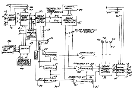
In FIG. 1 a color correction sy6tem has video
input terminal6 10, 11 and 12 for receiving
red/green/blue component color 6ignal6, respectively,
to be color corrected and video output terminals 13,
14 and 15 at which the corrected red/green/blue
component color signal~ appear. Input terminals 10,11
and 12 are connected by an input bypass relay 16, and
13~g~86
a color bar relay 17 to a color component input matrix
18. The red/green/blue component color signals are
coupled to a white amplifier and matrix 19, which
produces a white signal at a video output terminal
20. In matrix 18 the red/green/blue component color
signals are converted to difference signals, R-Y and
B-Y, and a luminance signal Y. The difference signals
are coupled to color correction circuitry 21, which as
described in greater detail in connection with FIGS. 2
through 5 modifies, i.e. corrects the difference
signals responsive to control signals from a control
panel 22. The luminance signal and the difference
signals from matrix 18 are coupled through delay
circuits 23, 24 and 25, respectively, and multipliers
26, 27 and 28, respectively, to one input of summing
amplifiers 29, 30 and 31, respectively. The color
correction signals from circuitry 21 are coupled to
the other input of each of summing amplifiers 29, 30
and 31. The corrected luminance signal appears at the
output of summing amplifier 29. The corrected
difference signal R-Y appears at the output of summing
amplifier 30. The corrected difference signal B-Y
appears at the output of summing amplifier 31.
Summing amplifier 29 is directly connected to a color
component output matrix 32. Summing amplifier 30 is
connected by a multiplier 33 to matrix 32. Summing
amplifier 31 is connected by a multiplier 34 to matrix
32.
A control terminal 35 to which a luminance level
control signal (e.g., a range of + or - 5 volts DC) is
applied is connected to multiplier 26, to permit
adjustment of the level of the luminance signal Y. A
control terminal 36 to which a saturation control
1 3~g3~
signal (e.g., a range of + or - 5 volts DC) is applied
is connected to multipliers 27 and 28 to permit
adjustment of the saturation level of the uncorrected
R-Y and B-Y difference signals. As a result, it is
possible to reduce, to the point of black and white if
desired, the saturation of the uncorrected portions of
the color signals. A control terminal 37 to which a
saturation level control signal (e.g., a range of + or
- volts DC) is applied is connected to multipliers 33
and 34 to permit adjustment of the saturation level of
the corrected R-Y and B-Y difference signals.
The red/green/blue component color signals from
matrix 32 are coupled through an output bypass relay
41 to video output terminals 13, 14 and 15,
respectively. Corrected luminance signal Y and
difference signals R-Y and B-Y pass directly through
matrix 32 to video output terminals 42, 43 and 44,
respectively. Matrix 18 and 32 are conventional
circuits for converting between red/green/blue
component color signals and luminance and difference
signals. Video buses 45, 46 and 47 are connected
between input bypass relay 16 and output bypass relay
41 to permit direct transmission of the red/green/blue
component color signals from input terminals lO, 11
and 12 to output terminals 13, 14 and 15, bypassing
the color correction circuitry.
For purposes of testing the described color
correction system and facilitating the establishment
of the desired color correcting control signals by the
colorist, a standard six color bar generator 47a and
an expanded thirty color bar generator 48 are
provided. Color bar generator 47a produces
1339~85
red/green/blue component color signals representing a color
chart with a white bar and six color bars; namely, yellow,
cyan, green, magenta, red and blue. As described in
connection with FIGS. 11 and 12, color bar generator 48
produces red/green/blue component color signals representing
an expanded thirty color bar chart. Either generator 47 or
generator 48 is alternatively connected to color bar relay 17
by a switch 49. Color bar relay 17 permits the red/green/-
blue component color signals from one of the color bar
generators to be substituted for the red/green/blue component
color signals to be corrected.
Reference is made to ~IG. 11 for diagrams
representing the red/green/blue component color signals and
the luminance signal for the expanded thirty color bar chart.
The thirty color bars are represented on the abscissa and the
normalized amplitude of the corresponding component signal is
represented on the ordinate. Thus, for example, color bar
#24, which lies between red and magenta, contains 100% of
red, 0% of green and 60% of blue. (The precise normalized
amplitude values of the luminance signal are presented below
the corresponding color bar identifying numbers on the
abscissa.) The color bars corresponding to the component
~primary) color signals (i.e. color bars #1, 11 and 21)
contain 100% of the corresponding component color signal and
0% of the remaining component color signals. The color bars
corresponding to the secondary hues cyan, yellow and magenta
(i.e. color bars # 6, 16 and 26) contain 100% of two of the
component color signals and 0% of the third (e.g. for yellow,
100% of red, 100% of green and
13~8fi
0~ of blue). Each of the component color signals is
100% of green and 0% of blue). Each of the component
color signals is 100% between the hues adjacent
thereto (e.g. the red component color signal is 100%
between yellow and magenta) and drops off in step-wise
fashion at 20~ increments moving away from the
adjacent hues. The result is that on both sides of
the color bars corresponding to the primary and
secondary hues (color bars #1, 6, 11, 16, 21 and 26),
the color bar is produced by the combination of a
step-wise component and a 100% component (e.g. color
bars # 17 to 20 are composed of a step-wise component
of green and a 100% component of red.).
As depicted in FIG. 12, color bar generator 48 has
an input terminal 50 for receiving a composite sync
signal containing both horizontal and vertical
synchronizing pulses. Terminal 50 is connected to a
line drive circuit 51 and a frame drive circuit 52.
Circuit 51 produces for each line of the video raster
one line drive pulse which is applied as a
synchronizing signal to an oscillator 53. Oscillator
53 produces pulses equal in number to the color bars
to be displayed, i.e. thirty color bars. (If desired,
thirty one colors bars could be displayed, the pure
blue color bar, bar #1, being repeated at the end of
the chart). Oscillator 53 drives a hue counter 54.
Memory devices (EPROM) 55a, 55b and 55c, latches 56a,
56b and 56c, and digital-to-analog converters (DAC)
57a, 57b and 57c are provided to generate the red,
green, and blue component color signals representing
the color bars. DACs 57a, 57b and 57c are connected
to switch 40 (FIG. 1). The output terminals of hue
- counter 54, six in number, are connected as address
8 6
inputs to EPROMs 55a, 55b and 55c, in which are stored
digital signals representing the red, green and blue
component signal values shown in FIG. ll for the
various color bars. For example, in the memory
location for color bar #24 in EPROM 55a a value
corresponding to 100~ of full amplitude is stored to
represent the component red signal, in EPROm 55b a
value corresponding to zero is stored, and in EPROM
55c, a value corresponding to 60% of full amplitude is
stored. Latches 56a, 56b and 56c store the outputs of
EPROMs 55a, 55b and 55c, respectively, while these
outputs are converted to analog signals by DACs 57a,
57b and 57c, respectively.
The addresses from hue counter 54 are coordinated
with the digital signals stored in the memory
locations of EPROMs 55a, 55b, and 55c, so that during
each video raster line, the digital signals generating
the color bars are delivered by EPROMs 55a, 55b and
55c in the order shown in FIG. ll, i.e. color bars #l
to 30 in sequence. Once each frame, circuit 52
produces a drive pulse which is coupled through an AND
gate 58 to the reset terminal of hue counter 54. For
synchronization purposes, the output of oscillator 53
is also coupled to AND gate 58.
Preferably, the color bar generator is also
capable of producing a plurality, e.g. fifteen
different levels of saturation for each color bar,
increasing in saturation from top to bottom. To this
end, the output of oscillator 53 is connected to a
divider 59, which produces one pulse for each of a
plurality, e.g. sixteen, of applied pulses. The
divisor can be changed by changing the binary signals
~3.39~6
applied to control terminals 61, e.g~ if the signals
are 1, 1, 1, 1, the divisor is one and only one level
of saturation is produced and if the signals are 0, O,
O, O, the divisor is sixteen and sixteen levels of
saturation are produced. The output of divider 59 is
connected to a saturation counter 60. The outputs of
saturation counter 60, four in number, are connected
as address inputs to EPROMs 55a, 55b and 55c. In
addition to digital signals representing the values of
full saturation for each of the thirty color bars,
EPROM 55a, 55b and 55c also store digital signals
representing fourteen other saturation levels between
zero and 100% for each color bar. In other words,
each of EPROMs 55a, 55b and 55c have four hundred
fifty memory locations. Each of the fifteen
saturation levels are displayed on each color bar from
top to bottom in decreasing saturation level, i.e.,
100% is at the top of the color bar and 0% is at the
bottom of the color bar. The result is a grid of
changing hue in horizontal rows and changing
saturation in vertical columns. After each sixteen
lines of the video raster, the memory locations of
EPROMs 55a, 55b and 55c corresponding to the hue for a
different saturation level are addressed. The
addresses generated by saturation counter 60 are
coordinated with the digital signals stored in the
memory locations of EPROMs 55a, 55b and 55c so as to
address a group of memory locations in which are
stored, the hue representative of the digital signals
corresponding to one saturation level after the
other. Thus, in the course of generation of each
frame of the color bar chart, the proper memory
location of each of EPROMs 55a, 55b and 55c is
addressed in succession to provide an image which is a
13395~
11
grid of horizontal rows of the same saturation and
vertical columns of the same hue. To select a
different number of saturation levels, the binary
signals applied to control terminals 61 are simply
changed to change the divisor.
For a description of how the invention selects the
desired hue angle and hue spread for color correction,
reference is made to FIG. 6, which is a chrominance
plane representation of the six primary and secondary
component color signals. The abscissa represents the
component color difference signal B-Y, i.e., blue
minus luminance. The ordinate represents the
component color difference signal R-Y, i.e., red minus
luminance. The letters M, R, Y, G, C, and B represent
the primary and secondary component color signals,
magenta, red, yellow, green, cyan, and blue in a polar
coordinate system. The angle represents the hue,
i.e., color, and the radius represents the saturation
level. A dot-dashed line 65 represents a desired hue
angle, in this case between magenta and blue, to be
color corrected at an angle a relative to the B-Y
axis. Dashed lines 66 and 67 represent a desired
sector with a color spread of angle k about hue angle
a over which the color correction is desired. The
invention permits both the hue angle a and the sector
spread or width k to be controlled so as to select any
desired sector in the chrominance plane over which to
introduce correction of the component color signals.
Reference is made to FIG. 2 for a description of
color correction circuitry 21, which comprises a
plurality of parallel channels CHl, CH2 and CH3. Any
number of further channels could also be provided,
~33~8~
depending upon the number of selective color
corrections to be made. The R-Y and B-Y uncorrected
video color signals from matrix 18 are coupled to each
channel. A different set of five correction control
signals is applied to each of channels CHl, CH2 and
CH3 as represented at 68, 69 and 70. The correction
control signals are DC, e.g., + or - 0 to 5 volts, as
distinguished from video, and remain fixed in value
once set until a different correction is to be made.
The correction control signals are generated by
the adjustment of potentiometers on control panel 22
by the colorist. Alternatively, the color control
signals generated by the colorist at control panel 22
could be stored in a computer memory and called up by
the computer in real time as the red, green, blue
component color signals are being transmitted from
input terminals 10, 11 and 12 to output terminals 13,
14 and 15 responsive to a frame counter in well-known
fashion. Responsive to each set of control signals, a
different color correction is introduced in each of
channels CHl, CH2 and CH3. The outputs of channels
CHl, CH2 and CH3 are additively combined such as, for
example, by an operational amplifier (not shown) to
produce R-Y, B-Y and Y video color correction signals
which are added to the uncorrected video color signals
B-Y, R-Y and Y from matrix 18 in summing amplifiers
29, 30 and 31, respectively (FIG. 1).
Reference is made to FIG. 3 for a description of
channel CHl. Channels CH2, CH3 and any further
channels desired to be added are identical to channel
CHl. The R-Y and B-Y uncorrected video signals are
applied to angular hue rotation circuitry 71 through
13 ~ 8 6
means for receiving video color component difference signals
at an input of the angular hue rotation circuitry. The
angular hue rotation circuitry defines a hue angle
representing a hue signal to be passed from the receiving
means to the means for transmitting corrected video color
component difference signals (described more fully below).
The set of five correction control signals from control panel
22 are applied, respectively, to input control terminals 72,
73, 74, 75 and 76. A control signal representative of a
first input signal in the form of the selected hue angle is
applied to input terminal 72. Terminal 72 is connected to a
sine generator 83 and a cosine generator 84. A signal
representative of the sine of the selected hue angle is
coupled from generator 83 to circuity 71. A signal
representative of the cosine of the selected hue angle is
coupled from generator 74 to circuitry 71. Responsive to
these signals, circuitry 71 presents at an output terminal 86
a video signal having a maximum amplitude when the R-Y and B-
Y uncorrected video signals form the selected hue angle and adecreasing amplitude moving away from the selected hue angle
within the fixed hue sector and a zero amplitude for all
other hue angles, i.e., all hue angles outside the fixed hue
sector. Responsive to a second input signal in the form of a
control signal representative of the selected hue spread
applied to terminal 73, hue spread circuitry 78 reduces the
width of the sector over which the signal appearing at
terminal 86 is non-zero. The hue spread circuitry is coupled
between the angular hue rotation circuitry 71 and multipliers
88-90, described more fully below, for defining a hue sector
containing the hue angle and representing hue boundaries
outside of which hue
,~
1339~86
signals representing hues outside of the hue sector
are not passed to the multipliers 88-90. Thus,
circuitry 78 produces an isolated color signal only
when the R-Y and B-Y uncorrected video signals lie
within the selected hue sector, which is the same or
narrower than the fixed hue sector transmitted by
circuitry 71. The isolated color signal is applied to
one input of an R-Y multiplier 88, one input of a B-Y
multiplier 89 and one input of a luminance multiplier
90. Terminal 74 is connected to the other input of
multiplier 90 to multiply the signal representative of
luminance correction by the isolated color signal.
Terminal 75 is connected to the other input of
multiplier 89 to multiply the signal representative of
the B-Y hue correction by the isolated color signal.
Terminal 76 is connected to the other input of
multiplier 88 to multiply the signal representative of
the R-Y hue correction by the isolated color signal.
As a result, video signals representative of the color
correction prescribed by the control signals applied
to terminals 74, 75 and 76 over the hue sector
prescribed by the control signals applied to terminals
72 and 73 are produced by multipliers, 88, 89 and 90
through means for transmitting corrected video color
component difference signals from the outputs of the
multipliers 88-90. The signals are combined with
corresponding video color correction signals from the
other channels by means of operational amplifiers 62,
63 and 64.
Reference is made to FIG. 4 for a more detailed
description of angular hue rotation circuitry 71.
Multipliers 91, 92, 93 and 94 rotate the R-Y and B-Y
uncorrected video signals under control of the sine
8 ~
and cosine representative signals. To this end, the
R-Y signal and the cosine representative signal are
applied to the inputs of multiplier 91; the B-Y signal
and the sine representative signal are applied to the
inputs of multiplier 92; the R-Y signal and the sine
representative signal are applied to the inputs of
multiplier 93; and the B-Y signal and the cosine
representative signal are applied to the inputs of
multiplier 94. The outputs of multiplier 91 and 92
are combined and applied to one input of a matrixing
circuit 95. The outputs of multipliers 93 and 94 are
combined and applied to the other input of matrixing
circuit 95.
In well known fashion, matrixing circuit 95
produces four color difference signals, namely, red
minus green (R-G), red minus blue (R-B), green minus
blue (G-B) and blue minus green (B-G). In this
connection, reference is made to FIG. 8 for diagrams
depicting red, green, and blue color component signals
(left in FIG. 8), the difference signals produced by
matrixing circuit 95 for a standard six color bar
chart (center in FIG. 8), and the signals produced at
the output of the angular hue rotation circuitry
(right in FIG. 8). The R-G, R-B, G-B and B-G
difference signals are applied to clippers 96, 97, 98
and 99, which remove the positive going (shaded in
FIG. 8) portions from the difference signals. The
negative going portions of the R-G and B-G difference
signals are coupled to a non-additive mixer 100 having
an output terminal 85. The negative going portions of
the R-G and R-B difference signals are applied to a
non-additive mixer 102 having an output terminal 86.
The negative going portions of the R-B and G-B
16 ~ 3 .3~g .58 6
difference signals are applied to a non-additive mixer
104 having an output terminal 87. In the left column
of FIG. 8, the R, G, and B component color signals are
shown for a standard six color bar chart. In the
center column, the difference signals R-B, G-B, R-G
and B-G are shown. Clippers 96 to 99 remove the
positive going portions of these signals.
Non-additive mixers 100, 102 and 104 transmit only the
most negative signal applied to their respective
inputs, suppressing the positive going portions. The
signals produced at output terminals 85, 86 and 87, by
virtue of the processing of the stated difference
signals by clippers 96 to 99 and mixers 100, 102 and
104 are depicted in the right column of FIG. 8 for a
standard six color bar chart. As illustrated, the
opposite, i.e., negative of the green (G) component
signal appears at the terminal 85, the opposite of the
cyan (C) component appears at the terminal 86, and the
opposite of the blue (B) component signal appears at
terminal 87. In summary, clippers 96 and 99 and
mixers 100, 102 and 104 serve to transmit from
matrixing circuit 95 to terminal 86 only video
component color difference signals which lie within a
fixed hue sector of preferably about 106~, i.e., the
sector between green and blue centered on cyan. Only
difference signals that lie within a sector between
yellow and cyan and centered on green are transmitted
to terminal 85. Only difference signals that lie
within a sector between cyan and magenta and centered
on blue are transmitted to terminal 87. Since the hue
transmitted to output terminal 86 is cyan, which is
located at an angle of -76.6~ on the chrominance
plane represented in FIG. 6, the selected hue angle in
general is angle a minus 76.6~.
17 ~39~86
By varying the selected hue angle, multipliers 91
to 94 in essence rotate the uncorrected video signals
applied thereto so as to permit any desired sector of
hue in the chrominance plane found in the color
difference signals, R-Y, B-Y, to be transmitted to
terminals 85, 86 and 87 in place of green, cyan and
blue. A few examples will illustrate this point with
reference to FIG. 7, which represents the sine and
cosine signals applied to multipliers 91 to 94 as a
function of the selected hue angle. If the selected
hue angle is O~, the cosine signal is a maximum
positive value and the sine signal is zero. As a
result, the R-Y difference signal and the B-Y
difference signal are transmitted at full amplitude by
multipliers 91 and 94, respectively, to matrixing
circuit 95, while transmission of the difference
signals by multipliers 92 and 93 is blocked. When the
selected hue angle is +90~, multiplier 93 transmits
the R-Y difference signal to input terminal 81, and
multiplier 92 transmits the B-Y difference signal to
input terminal 80 at full amplitude, while
transmission through multipliers 91 and 94 is
blocked. With reference to FIG. 6, this is e~uivalent
to rotating the R-Y and B-Y axes 90~ in a
counterclockwise direction and the hue sectors
transmitted to output terminals 85, 86 and 87 change.
Thus, difference signals centered at a hue between
blue and magenta represented by a dashed line 38 at an
angle 13.4~ in relation to the origin (positive B-Y
axis) in FIG. 6 are transmitted to output terminal 86,
difference signals centered at a hue between red and
magenta represented by a dashed line 39 at an angle of
77.1~ in FIG. 6 are transmitted to output terminal
87, and difference signals centered at a hue between
1~3~86
18
cyan and blue represented by a dashed line 40 at an
angle of 330.8~ in FIG. 6 are transmitted to output
terminal 85. When the selected hue angle is 180~,
multipliers 91 and 94 invert the polarity of the R-Y
and B-Y difference signals, respectively, while
transmission through multipliers 92 and 93 is
blocked. This is equivalent to rotating the R-Y and
B-Y axes in FIG. 6 by 180~.
Assuming application of the expanded thirty color
bar difference signals to angular hue rotation
circuitry 71, and a selected hue angle of 0~, FIGS.
9A, 9B and 9C represent the signal amplitude in volts
at terminals 87, 86 and 85, respectively. As
illustrated, the signal at terminal 87 is a maximum
negative value at blue, drops off toward magenta and
cyan, and is zero for all other hues, the signal at
terminal 86 is a maximum negative value at cyan, drops
off toward blue and green, and is zero at all other
hues, the signal at terminal 85 is a maximum negative
value at green, drops off toward cyan and yellow, and
is zero at all other hues. As the selected hue angle
increases and decreases from zero, the signals at
terminals 87, 86 and 85 change in value, shifting as a
unit back and forth in the hue spectrum relative to
their values illustrated in FIGS. 9A, 9B and 9C.
With reference to FIG. 5, which depicts the hue
spread circuitry, terminals 85 and 87 (FIG. 4 ) are
connected to a non-additive mixer 110. The output of
non-additive mixer 110 is coupled by an operational
amplifier 111, supplying a preferably fixed gain to
the signal from the non-additive mixer 110, to one
input of a non-additive mixer 112. Terminal 86 is
~339~8~
connected by an invertor 114 to the other input of
non-additive mixer 112. The output of non-additive
mixer 112 is coupled by a negative signal clipper 115
to a terminal 116, which serves as the output for
circuitry 78. Terminal 73 is connected by a resistor
117 to the input of operational amplifier 111.
Mixers 110 and 112 transmit the more negative of
the signals applied to their inputs. Therefore, the
wave form of the signal at the output of mixer 110 is
a combination of FIGS. 9A and 9C. The signal
representing the selected hue spread applied to
terminal 73 serves to bias the signal at the output of
mixer 110 upwardly or downwardly, depending upon the
angular width of the selected hue sector. This is
illustrated in FIG. lOA, which represents the output
of operational amplifier 111. As indicated by the
two-headed arrow, the signal produced at amplifier 111
responsive to the expanded color bar component
difference signals moves upwardly or downwardly
relative to zero volts depending on the amplitude of
the selected hue spread representative control
signal. FIG. lOB represents the signal at terminal 86
after passing through invertor 114 responsive to the
expanded color bar component difference signals, which
is fixed relative to zero volts. FIG. lOC represents
the signal at the output of clipper 115. As the bias
applied by the signal at terminal 73 increases in a
positive direction, more of the signal at the output
of mixer 112 lies above zero volts and the angle of
the selected sector widens because clipper 115 passes
a wider band of hue, and vice-versa. As previously
described, only when the uncorrected video signals
applied to circuitry 71 lie within the selected hue
133g~86
sector about the selected hue angle is a signal produced at
terminal 116. With reference to FIGS. lOA, lOB and lOC,
operation of the invention may be understood by viewing
changes in the selected hue angle as lateral shifting of the
wave forms and changes in the selected hue spread as up and
down shifting of wave forms lOA and lOC.
The white amplifier and matrix 19, shown in FIG. 1,
includes a pair of linear ANDing circuits ~FIG. 13), which
is a circuit analogous to an analog form of an ANDing circuit
for combining the three RGB signals together so that the
output of the second linear ANDing circuit contains only the
white signal portions from each of the red, green and blue
signals. The output of the pair of linear ANDing circuits is
shown in FIG. 13. The output is then applied to a trio of
multipliers, in a manner similar to the application of the
output from the angular hue spread circuitry 78 to the R-Y
multiplier 88, B-Y multiplier 89 and luminance multiplier 90.
The outputs of the three multipliers can then be combined
with the output signals from the color correction channels on
the common output fuse for producing a corrective video
output.
The described embodiment of the invention is only
considered to be preferred and illustrative of the invention
concept; the scope of the invention is not to be restricted
to such embodiment. Various and other numerous arrangements
may be devised by one skilled in the art without departing
from the spirit and scope of this invention. The invention
may be employed in a telecine film chain of in video tape-to-
video tape conversion equipment, or any other setting inwhich video component color signals appear.