Note: Descriptions are shown in the official language in which they were submitted.
~340209
BIOLOGICAL SAMPLE ANALYZER
Some of the subject matter described and not claimed in
this application is described and claimed in copending
application serial number 607,32~.
~ACKGROUND OF THE INVENTION
The present invention relates generally to
biological sample analyzers and more specifically to a
semi-automated analyzer and subsystems thereof capable
of simùltaneously carrying out a panel of assays on
each of a plurality of different biological samples.
In one aspect, the analyzer of the invention is adapted
to simultaneously assay each of a plurality of biological
fluid samples for human IgE class antibodies specific
to a preselected panel of allergens.
A significant portion of the population has
some allergic reaction to substances such as pollen,
animal dander, or other commonly present allergenic
substances. A key element in the treatment of such
allergic symptoms is identlfication of the particular
substance to which a person may be allergic. Previous
methods for determining allergic hypersensitivity were
performed using direct skin tests on the patient. In
these direct sXin tests minute quantities of various
allergens were injected into or under the patient s
skin and the particular patch of skin was subseguently
examined to determine whether or not a person had an
allergic reaction to the previously introduced
allergen.
* .
- 2 - 13~0209
-
In addition to being uncomfortable for the
patient, patients on certain medications (i.e.
antihistamines) cannot be accurately tested by direct
skin tests.
Accordingly, a number of in-vitro testing
procedures have been developed. Such procedures detect
circulating IgE in serum or plasma or other microbiolog-
ical interreactions using an insoluble solid carrier
coated with a known quantity of antigen extract derived
from a known allergenic substance. The coated carrier
is typically exposed to, and incubated in, a sample of
the patient's blood serum. If the patient carries the
IgE class antibody which is specific to the particular
allergen and which is the cause of the patient's aller-
gic reaction to the allergen, a measurable binding reac-
tion occur# on the carrier during the incubation period.
The concentration of the IgE antibody in the sample and
accordingly the degree of allergic sensitivity of the
patient is then determined by measuring the magnitude
of the binding reaction either visually, photometri-
cally, fluorometrically, radiologically, enzymatically,
or by other known techniques.
While such in-vitro procedures provide ad-
vantages over in-vivo testing procedures, they are not
without disadvantages. First, a relatively large
quantity of blood is required to test the patient's
sensitivity to a large number of specific allergens.
Second, testing for a large number of different allergens
in separate cuvettes is tedious and time consuming for
the physician or technician performing the test.
To this end, efforts have been devoted to
develop a system which simultaneously tests for a number
of specific allergens utilizing a single sample of the
. .
~ 3 ~ 13~0209
-
patient's blood serum. For example, U.S. Patent Nos.
3,941,876 (Marinkovich) and 4,031,197 (Marinkovich)
disclose techniques for the screening of different IgE
class antibodies. The techniques taught by Marinkovich
involve coating an elongated cellulosic body, such as a
strip of paper, with separate identified allergens to
form bands or islands, which are separated from one
another by allergen-free areas. The coated cellulose
material is then contacted with a test serum so that
serum IgE class antibodies specific for the coated
allergens will bind to the appropriate bands or islands.
The cellulosic body is then washed and subsequently
incubated with labelled antibodies that are reactive
with the attached IgE class antibodies. The bands or
islands are then analyzed for the presence of the
labeled antibodies.
U.S. Patent No. 4,459,360 (Marinkovich) also
discloses a similar multiple-component binding assay
system which include~ a plurality of coated filaments
mounted on a support for simultaneously screening a
liquid test sample for a plurality of components. Each
of the filaments, which are preferably cotton threads,
is used to bind a different allergen.
Another example of presently available in-
vitro devices is given in U.S. Patent No. 4,567,149
(Sell et al.), which discloses an apparatus including a
well which contains a plurality of elongated strips.
Each strip is coated with a separate assay binding
component such as an antigen or allergen. The well
is adapted to contain a liquid specimen for incubation
with the strips. After the incubation process the
liquid specimen is removed and the binding reaction
which occurred on each strip is determined by known
methods.
- - 13~20~
Still a further device which may be used for
effecting a plurality of antibody-antigen reactions
simultaneously in one operation is disclosed in Euro-
pean Patent Application No. 0 063 810 Al (Gordon
et al.). The Gordon reference teaches a device for
carrying out immuno-assays which comprises a solid
porous support, preferably made of a nitrocellulose
material, having antigens and/or immunoglobulins bound
thereon by direct application, thereby forming an array
of test areas. The array thus formed comprises a plu-
rality of dots or lines of the antigen and/or immuno-
globins.
Various systems are available which may be
used in conjunction with the above-described multiple
component binding assay systems to quantify the reac-
tions which occur on the carriers. Eor example, U.S.
Patent No. 4,558,013 (Marinkovich et al.) discloses an
apparatus (which may be used in conjunction with a
device such as the one taught by Sell et al.) in which
a carrier with an uncoated reference region is used to
manually produce a strip of photographic film having a
linear array of spots or stripes. Each spot or stripe
on the film has an optical density indicating the magni-
tude of the binding reaction on a particular test strip
or thread. A scanning densitometer is then used to
successively measure the optical density of each fnm
strip, thereby providing a quantitative measure of a
patient's reaction to the various allergens.
Another device which may be used with the
above-de~cribed multiple component binding assay systems
to quantify the reaction of each specific allergen is
taught in U.S. Patent No. 4,510,393 (Sell et al.) which
disclose~ a portable photo chamber which is used to
manually photographically record the magnitude of a
chemical reaction evidenced by the emission of radio-
. ... _ .. .. _
~ 5 ~ 1340209
.
activity by a substrate labelled with a radioactivetracer.
Although these methods provide advantages
over previously available in-vitro methods, and over
the in-vivo methods, they are not without limitations.
One major limitation is the fact that the methods for
effecting and measuring the reactions on the above-
described multiple test spot devices require an exten-
sive amount of manual manipulation by the physician or
technician performing the test, which increases the
time, cost, and risk of error associated with such
tests. For example, known in-vitro procedures require
that the multicomponent biological test carriers be
manually contacted with the liquid sample being
analyzed, removed from the liquid sample, washed, and
then incubated with a solution typically containing a
labeled second antibody that is reactive with human IgE
class antibodies. Subsequently the carrier must be
manually removed from the solution and the magnitude of
the resulting binding reaction on the solid phase be
then determined by autoradiographical analysis in
conjunction with densitometric analysis as proposed by
Marinkovich, by fluorometry, or by other known
techniques.
In addition, the washing step identified above
normally comprises a multi-step procedure including
removing waste fluid (for example used reagent or
sample solution), adding wash solution, agitating the
wash solution for a predetermined time period, removing
used wash solution, adding more wash solution, and
repeating the cycle two or more times before adding the
next reagent. If a number of patient samples are to be
analyzed simultaneously, the hands-on time requirements
are further magnified. For instance, if ten patient
samples were to be analyzed, each washing step alone
._ . ....... . ...
- 6 - 1340209
. .
could involve performing 90 washes. This would
probably require a minimum of approximately 30 minutes
hands-on time for the technician or physician for each
washing step required.
A number of analyzers for automatically
analyzing a plurality of biological samples are known.
Such analyzers typically include automated apparatus
for providing wash, reagent, and sample fluids, and
automated apparatus for measuring the results of the
tests on the samples. See, for example, U.S. Patent
Nos. 4,427,294 (Nardo); 4,451,433 (Yamashita, et al.);
4,406,547 (Aihara); 4,634,575 (Kawakami, et al.);
3,964,867 (Berry); and 4,061,469 (DuBose).
Although these analyzers generally automate
the analysis of a plurality of biological samples for
the presence of a particular substance, none are
suitable for carrying out the procedures required to
simultaneously analyze a plurality of patient samples
in a plurality of test cartridges each containing a
plurality of different test sites and each adapted to
simultaneously perform a complete panel of tests on a
single sample.
Available systems have still further limita-
tions. For instance, the accuracy of test results de-
rived from devices such as those disclosed by Gordon et
al. may be less than optimal. Since the test dots in
the Gordon et al. device are formed by direct contact
of the specific allergen with the nitrocellulose without
an effective means for confining or isolating the aller-
gen to a specific area, the accuracy and reliability of
the results achleved with this device are affected.
Specifically, if the dots are arranged in close prox-
imity to each other there is a possibility that an
allergen from one test dot will migrate onto a neighbor-
ing test dot when the allergen is applied to the
.. . . . .. ..
~ 7 ~ 1340209
., .
support. This migration adversely affects the accuracy
of the determination of the patient's reaction to the
allergen associated with the neighboring test dot.
Second, since the specific allergens are not confined
to a predetermined area, the concentration of allergen
will vary from dot to dot on each carrier and from
carrier to carrier. As a result, depending on the
detection technique employed, dot to dot variations in
optical density or in the intensity of optical or other
radiation resulting from the binding reactions on a dot
will occur in dependence on the area over which the
allergen initially dispersed during the initial contact
with the support. Such variations have a substantial
adverse affect on the uniformity and repeatability of
test results.
Therefore, in view of the above, it is a
general object of the present invention to provide a
biological sample analyzer which may be used to
automatically and simultaneously carry out a panel of
tests on each of a plurality of patient samples.
It is a more specific object of the present
invention to provide reaction cartridge means which are
adapted for use in such an analyzer to simultaneously
test a patient sample for a plurality of different
components with a single addition of patient sample and
selected reagents and which provides test results -
accessible by an optical reader directly on the
reaction cartridge.
It is also a more specific object of the
present invention to provide reaction cartridge
conveying means for such an analyzer including means to
accurately and uniformly position a plurality of such
cartridges in three separate dimensions so that an
optical reader can accurately and uniformly read the
results of a plurality of tests on each of a plurality
of patient samples.
-- 7 --
.. _ . . .. . . . . . . .
- 8 - 13~0209
It is also a more specific object of the
present invention to provide means adapted use with
such an analyzer to provide access to a large volume of
predetermined assay calibration data, such means
preferably including reaction cartridge means provided
with code means to access corresponding assay
calibration data in a data storage means.
SUMMARY OF THE INVENTION
To achieve the foregoing and other objects
and in accordance with the purposes of the present inven-
tion, automated apparatus for testing each of a
plurality of biological samples for a plurality of
selected assay binding components simultaneously is
provided.
The apparatus includes reaction cartridge
apparatus having a plurality of test sites each bound
with a preselected first assay binding component which
is adapted to capture a specific second a~say binding
component of interest in a biological sample.
Cartridge conveying apparatus or rack means
having a plurality of mounting locations each adapted
to hold a reaction cartridge is operative to
selectively convey the reaction cartridges to positions
at which selected biological samples and reagent fluids
are introduced to the test sites on each cartridge ~o
simultaneously carry out a preselected panel of tests
on each sample. The cartridge conveying apparatus is
further operative to selectively convey the reaction
cartridge~ to a test result reading position.
Test result reader apparatus is provided to
read the results of the tests directly from the test
sites on the cartridges at the reading position.
In one aspect of the invention, a reaction
cartridge is provided which includes a plurality of
.... .
- 9 - 13~0209
isolated biological sample test sites contained within
a reaction well which is adapted to contain a
biological sample to be tested. The reaction well is
configured to provide direct optical access to each of
the test sites. The cartridge is further provided with
lock means which cooperate with lock means on a
cartridge-conveying carousel rack to position and lock
the cartridge in three dimensions in a predetermined
position on the rack. The rack preferably includes a
plurality of openings each adapted to receive a
cartridge.
In another aspect of the invention, apparatus
is provided for providing assay calibration data adapted
for use in assaying biological samples. Predetermined
assay calibration data-for normalizing the results of
at least one assay with respect to at least one prede-
termined standard value includes a first code for
identifying the at least one assay to which the
calibration data corresponds. The calibration data is
entered into a location in a data storage apparatus.
Apparatus such as a reaction cartridge, which is
adapted for use in carrying out at least one assay,
includes a second code corresponding to the at least
one assay. Apparatus responsive to the second code is
provided ~or correlating the second code to the first
code to access the calibration data in the storage -
apparatus.
The foregoing objects, advantages and novel
features of the invention as well a~ others will become
apparent to those skilled in the art upon examination
of the following detailed description of a presently
preferred embodiment of the invention in conjunction
with the appended drawings. The objects and advantages
of the invention may be obtained by means of the
instrumentalities and combinations particularly pointed
out in the appended claims.
_ g _
~ . . .. ~ ..
lO- 1340209
.
BRIEF DESCRIPTION OF THE DRAWINGS
Figure 1 i~ a perspective view of a preferred
embodiment of the biological sample analyzer of the
present invention..
Figure 2 is a perspective view of a preferred
embodiment of a reaction cartridge and a partial cutaway
view of a preferred cartridge-conveying carousel of the
present invention.
Figure 3 is a top plan view of a preferred
embodiment of the carousel of Figure 2 illustrating the
preferred cartridge positioning means of the present
invention.
Figure 4 is a bottom plan view of the carousel
of Figure 3.
Figure 5 is an enlarged top plan view of a
preferred embodiment of the reaction cartridge
illustrated in Figure 2.
Figure 6 is a partial sectional view through
lines 6-6 showing the cartridge mounted in the carousel
illustrated in Figure 3.
Figure 7 is a partial sectional view through
lines 7-7 showing the cartridge mounted in the carousel
illustrated in Figure 3.
Figure 8 is a magnified view, partially
cutaway, through lines 8-8 showing sample test sites in
a preferred laminate structure of the test card of ~he
present invention.
Figure 9 is a cutaway side elevational view
of a preferred embodiment of the boom arm and drive
arrangements of the present invention.
Figure 10 is a top plan view, partially in
phantom, illustratlng the range of motion of the
preferred boom arm of the present invention.
Figure 11 is an exploded perspective view,
partially cutaway, of a preferred embodiment of a
-- 10 -
11- 1340209
spring plate mounting arrangement for the boom arm and
carousel drive motors of the present invention.
Figure 12 is a sectional view of the optical
reader head of the present invention illustrating a
preferred embodiment of an optical reader for reading
test results.
Figure 13 is an electrical schematic diagram
illustrating a preferred embodiment of a signal
processing and control circuit for use with the optical
reader of Figure 12.
Figure 14 is a block diagram illustrating a
preferred embodiment of apparatus of the invention for
providing assay calibration data for use in testing
patient samples.
Figure 15 is-a block diagram illustrating a
preferred system control architecture of the present
invention.
Figure 16 is an exploded view of a preferred
embodiment of the well cover comprising a part of the
reaction cartridge of the present invention.
Figure 17 is an alternate preferred
embodiment of the well cover comprising a part of the
reaction cartridge of the present invention.
DETAILED DESCRIPTION OF THE
PRESENTLY PREFERRED EMBODIMENTS ~-~ -
Referring now to the drawings and specific-
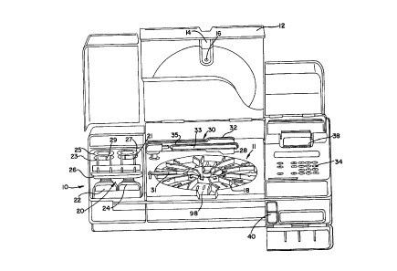
ally to FIGS. 1-10, a biological sample analyzer 10
includes a processing chamber 11 in which to test
biological samples. A chamber door 12 is preferably
hingedly mounted to the analyzer 10 overlying the
chamber 11 to selectively close off and provide access
thereto. Inset into the chamber door 12 is a
translucent viewing window 14 which allows an operator
to view the activity within the processing chamber.
- 11 --
...., ~ .
- 12 - 13~0209
The window 14 preferably includes a reagent addition
port 16 through which reagents can be introduced into
the chamber ll without opening the chamber door 12.
The processing chamber 11 contains a holding
rack, preferably in the form of a rotatable carousel 18
which serves two primary purposes. First, the carousel
18 comprises means for holding and conveying reaction
cartridges 80 in order to position the cartridges to
receive sample and selected reagents, to provide
agitation required for processing the samples and
~ reagents, and to position the cartridges for reading
test results therefrom. Second, the carousel 18
functions as a very precise optical bench, accurately
positioning each reaction cartridge 80 relative to an
optical reader 32, which is described in detail below,
to facilitate accurate and repeatable reading of test
results directly from the cartridges 80. Positioning
and alignment of the cartridges 80 is preferably
accomplished using a three-point system associated with
each cartridge 80. The three-point alignment system is
more fully de~cribed below. The carousel 18 also
preferably includes optical positioning means which is
used to provide precise alignment of the carousel and
the optical reader 32 in a manner described in detail
below.
As illustrated in FIG. l, the carousel 18~is
preferably disposed on a tilted axis. Rotation of the
carousel 18 about this tilted axis provides desirable
agitation of the fluids in a reaction well 86 of each
reaction cartridge 80 thereby promoting faster and more
complete reactions and allowing the use of smaller
volumes of sample and reagents than has previously been
possible. Rotation is preferably accomplished at a
speed less than 25 rpm to avoid the effects of
centrifugal force. Applicants have successfully used
- 12 -
- 13 - 1340209
rotational speeds in a range between 7 to about 20 rpm.
The carousel 18 is preferably tilted such that when a
reaction cartridge 80 is at the rear of the analyzer
10, the reaction cartridge 80 is at the top of the
tilt, thereby forcing fluid to collect at one end of
the reaction well 86 (towards the top of the reaction
cartridge as shown in FIG. 5). As the carou~el 18
rotates, fluid in the reaction well 86 flows across the
surface of a test card or panel 82 toward the other end
of the reaction well until the reaction cartridge 80
reache~ the bottom of the tilt (adjacent to the front
of the analyzer). The fluid motion is then repeated in
the opposite direction as the carousel 18 continue~ to
rotate the reaction cartridge 80 back toward the top of
the tilt, thereby providing desirable fluid agitation.
The tilt of the carousel 18 may be implemented
by any conventional support structure, but preferably
is implemented by mounting the carousel 18 on a base,
which i~ inclined at the desired angle by conventional
support means. A tilt angle of approximately 10~ is
presently preferred but, as will be recognized by those
skilled in the art, the tilt may be within any
appropriate range, for example 5-20~, which provides
the desired agitation.
A~ described above, in manual testing proced-
ures, washing of reaction supports or containers is by
far the most tediou~ chore for the person performing
the test. The presently preferred biological sample
analyzer 10 of the present invention eliminates these
tedious operator step~ by automating the washing function
using the combination of a microprocessor-controlled
wash/waste unit 20 and the tilted carousel 18.
The wash/waste unit preferably comprise~ a
dual chamber container which includes a chamber 22 for
holding wash solution, and a chamber 24 which provides
- 14 - 1340203
containment for waste fluid aspirated from the reaction
cartridges 80. A wash manifold 26 functions both as a
cover for the chambers and as a mount for wash tubing
23 and wa~te tubing 21. The cover 26 is preferably
provided with suitable sealing means to prevent
evaporation of the fluids contained in the wash and
waste chambers 22 and 24.
In a preferred embodiment, a liquid level
sensor (not shown) may be associated with the waste
chamber 24 to detect when the waste chamber 24 is full
and provide a detection signal. An optical sensor (not
shown) may also be provided to generate a detection
signal when the cover 26 is not in an appropriate
position (such as when the cover and/or the container
wash/waste container are removed).
Wash and waste fluids are caused to flow
through wash and waste tubing 23 and 21 by means of
peristaltlc pumps 25 and 27. The first peristaltic
pump 25 is operative to deliver wash solution from the
chamber 22 through tubing 23 while the second pump 27
is operative to aspirate waste fluids through the
tubing 21 and into the waste chamber 24. For reasons
which will become apparent, the waste pump 27 is
preferably operated to generate a higher flow rate than
the wash pump 25. Thus, the pin 29 of the wash pump 25
is disposed at a radius less than the radius of the-pin
of the waste pump 27. The selection, construction, and
operation of suitable peristaltic pumps is well known
to persons skilled in the art and a detailed descrip-
tion is not necessary to a complete understanding of
the invention.
Wash and waste fluids are preferably
introduced into and removed from the reaction wells 86
of reaction cartridges 80 mounted on carousel 18 by
means of a fluid probe 28 which i8 connected with the
- 14 -
. , _ . . . .. . . . . . . ..
- 15 - 1 ~ ~0 2 09
wash and waste tubing 23 and 21 and which is mounted
proximate the free end of a horizontal, pivotally-mounted
probe arm 33. In a preferred embodiment, fluid access
to a reaction cartridge 80 is provided when the
carousel 18 conveys the reaction cartridge 80 to a
preselected wash position (preferably around the one
o'clock position on the carousel 18 as viewed from the
front of the biological analyzer lO in FIG. l). At
this position, the tllt of the carousel 18 causes any
fluid in the reaction well 86 to gravitate towards a
corner of the reaction well 86. The probe arm 33 is
rotated so that the fluid probe 28 is positioned above
the reaction well 86 of the reaction cartridge 80. The
probe arm 33 then pivots downwardly, causing the probe
28 to dip down into the corner of the reaction well.
Pump 27 or 25 is then operated to either aspirate fluid
from or introduce fluid into the reaction well 86.
Details of the assay protocol are discussed
hereina~ter. Upon completion of a panel of tests, the
test results are preferably read by an optical reader
system which is more fully described below, but which
generally includes an optical reader 32 and an
associated control and signal processing circuit.
Briefly, the optical reader 32 includes a source of
optical radiation, an optical detector, and an array of
lenses, apertures and filters. The optical reader 32
is preferably mounted in a reader head which is in turn
disposed proximate the free end of a horizontal
rotatably-mounted optical reader arm 35. In order to
read a test result from a test site 84 on a reaction
cartridge, the reaction cartridge 80 is conveyed by the
carousel 18 to a predetermined reading position. The
reader arm 35 is then rotated out over the reaction
well 86 of the reaction cartridge 80 until the test
site 84 to be read is aligned directly under the
- 15 -
.. . . . . . . . ...
- 16 - 134020~
optical reader 32. The optical source of the optical
reader 32 then emits a beam of optical radiation onto a
small portion of the test site 84 and the optical
detector converts the intensity of the optical
radiation reflected by the diffuse surface o~ the test
site into an electrical signal. The signal is then
processed to obtain the optical density value of the
test site 84 which is directly related to the
concentration of a binding component of interest in the
biological sample which is specifically reactive with
the capture reagent or binding component disposed on
the test site. Under microprocessor control, the
carousel 18 and optical reader arm 35 move in
cooperation to sequentially position the optical reader
32 over each selected test site 84 until all selected
test sites 84 have been read.
As shown in FIG. 1, the biological sample
analyzer 10 preferably also includes a keyboard 34,
which may be used by an operator to enter data and in-
strument function commands. The analyzer also prefer-
ably includes a printer 38
which may be used to prompt the operator to taXe action
during a test cycle and to provide a record of test
results.
The keyboard 34 preferably includes numeric
keys that allow the user to enter data such as assay
calibration data or the patient I.D. number associated
with a certain reaction cartridge 80. The keyboard 34
also preferably includes instrument function keys
including for example an ENTER key which is operative
to enter data from the keyboard, a RUN key which is
operative to initiate or resume a test procedure and an
INDEX key which is operative to rotatably advance the
carousel 18 by one position. Other Xeys which allow
keyboard data to be cleared or which provide control
- 16 -
~''' .
- 17 - 1340209
c~ An~ for the printer (such as to eject paper or to
pause the test operation) may also be provided.
As mentioned above, a controlled test
environment is preferably provided in the processing
chamber 11. During an exemplary enzyme immuno assay
which is described in detail below for example, the
temperature in the chamber is preferably maintained at
approximately 35~C. Temperature in the processing
chamber 11 is suitably maintained at a selected level
by means of one or more conventional electric coil
heaters, fans, temperature sensors, and a temperature
control circuit in a manner well known to persons
skilled in the art. Most simply, for example, the
control circuit would operate to compare the analog
voltage across the thermistor with an analog reference
voltage corresponding to the desired temperature. If
the thermistor voltage were below the reference volt-
age, the control signal would issue a signal to turn on
the heater. The fan would operate to continuously
circulate air in the processing chamber 11. In a more
preferred embodiment, however, a microprocessor may
read the temperature from the temperature sensors at
predetermined intervals and control the heater to
maintain the temperature at the desired level.~ _ _ _ _ _The locatisns of the various temperature
control components are not critical. However, it is
preferable that any fans be mounted or the air from the
fans be directed in such a way as to avoid directly
circulating across the optics reader 32 and optical
reference means 70 which are described in detail below
in order to minimize depositing debris which may affect
the optical meacurements of test results. The
selection, con~truction and operation of the various
temperature control components are well known to
persons skilled in the art and further detailed
- 17 -
- 18 - 13~0209
explanation thereof is not necessary for a complete
understanding of the invention.
In addition to the temperature control com-
ponents described above a conventional electrical
resistance type heating strip 31 may be provided in the
reaction chamber 11 proximate to and overlying the
rotational path of the carousel 18 to apply additional
heat to reaction cartridges 80 as they are rotated on
the carousel 18. Use of such a heating strip 31 is
particularly advantageous in preventing condensation
from forming on the well covers 90 of the reaction
cartridges 86 which condensate can affect the
concentration of fluids in the reaction wells 86,
adversely affect test results, and constitutes a
biohazard.
In a particularly preferred embodiment, the
biological sample analyzer lO also includes optical
code reader means 306 which may be a conventional
optical bar code reader wand and associated processing
circuitry 308 (illustrated in FIG. 14). As described
in detail below, the optical code reader means 306 is
used to particular advantage to enter large amounts of
assay calibration data into the biological sample
analyzer 10, which data is then used in the preferred
emboc~ment to normaLize the test results obtained from
various test sites 84 on various reaction cartridges
80. If desired, a storage compartment 40 can be
provided to store the optical code reader means 306
when not in use.
CAROUSEL AND REACTION CARTRIDGES
Referring now to FIGs. 1-7, a more detailed
description is given of the reaction cartridges 80 and
the carousel 18. As best illustrated in FIG. 5, the
preferred reaction cartridge 80 incl~des a test card B2
- 18 -
13~020~
which includes an array of test sites 84 preferably in
close proximity to each other. The test card 82 is
contained within a reaction well 86 which is defined by
a well wall 88. The reaction well 86 is preferably
provided with a removable, preferably transparent well
cover 90 which preferably includes a reagent port 92 to
facilitate the delivery and removal of fluids from the
reaction well 86.
The well cover 90 is preferably made of one
or more layers of a thin transparent material with
fairly resilient properties, such as a polyester film.
A suitable polyester film is commercially available as
MYLAR. The port 92 preferably is defined by multiple
slits in the well cover 90. The slits are preferably
disposed in one of the lower corners of the reaction
well 86 and arranged to define a generally Y-shaped
port. Since the cover 90 is made of a fairly resilient
material this arrangement provides a self-sealing port.
The cover 90 is preferably removably adhered to the top
of the well wall 88 using a suitable adhesive.
As described in more detail below, to further
enhance the sealing capabilities of the port 92 of the
cover 90, the port 92 preferably includes a second flap
system formed in a second layer of polyester film and
attached to the underside of the first layer of
polyester film of the cover 90.
A first preferred embodiment of the dual
layered cover including the second flap system as
illustrated in FIG. 16. The cover 90 includes a first
layer 400 bonded to a second layer 402 by a suitable
adhesive. The first layer 400 includes three slits
which intersect at a single point and are configured in
a generally Y-shaped arrangement. The Y-shaped slit
arrangement defines a first layer port 406 with a first
hinged flap arrangement. The second layer 402 includes
a pair of slits 412, 414 configured in a generally
-- 19 --
* Trade-mark
13~0209
- 20 -
V-shaped arranged which define a second layer port 408
with a second layer hinged flap arrangement. As illus-
trated in FIGs. 5 and 16, the first layer flap arrange-
~ ment and the second layer flap arrangement are disposed
such that the slits of each port 406, 408 do not directly
line up. In this manner the flap of the second layer
402 seals the slits of the port 406 in the first layer
400. The flap areas of both layers contain minimal or
no effective adhesive to insure free operation.
FIG. 17 illustrates another preferred embodimentof a dual layered cover 90 including a second flap system.
The first or top layer 401 has a Y-shaped port 43 configur-
ation similar to the port 406 of the first layer 400 of
the embodiment illustrated in FIG. 16 and discussed
above. The second layer 404 includes slits 416, 418
and 420. The slits 416 and 418 are disposed such that
they define a generally Y-shaped slit arrangement. The
slits 418 and 420 are disposed such that the two slits
418 and 420 define a generally V-shaped arrangement.
The three slits 416, 418 and 420 define a second layer
port 410 with a second layer flap arrangement. As with
the embodiment illustrated in FIG. 16, the flap arrange-
ment of port 406 and the flap arrangement of the port
410 are disposed such that the slits of each port 406,
410 do not directly line up.
With the preferred embodiments of the port 92
illustrated in FIGs. 16 and 17, when the probe or syringe
needle, for example, enters the reaction well 86 through
the slits at the Y-shaped port in the first or top layer,
the hinged flap in the bottom or second layer is pushed
down, thereby opening the port 92. When the probe 28
or needle is withdrawn, the hinged flap returns to its
normal position, sealing the slits of the port 92 and
thereby further enhancing the sealing capabilities of
the port 92.
- 20 -
- 21 - 13~209
The reaction cartridge 80 also preferably
includes code means 94 such as an optical bar code
which is attached to or printed directly on the flat
surface 91 of the reaction cartridge 80. The bar code
94 is adapted to be read by the optical reader 32 or by
other conventional optical reader means. In a particu-
larly preferred embodiment, the bar code 94 includes a
lot code which i8 advantageously used to access stored
assay calibration data corresponding to the particular
reaction cartridge 80 being tested. A more detailed
description of this feature of the invention is given
below.
The reaction cartridge 80 also preferably
includes a panel 96 which may include information such
as the expiration date of the particular reaction cart-
ridge, the lot number of the particular panel of the
capture reagents or assay binding components used to
manufacture the reaction cartridge, and a section on
which the operator may manually record information such
as a patient I.D. number and/or the date of the sample
being tested.
Referring now specifically to FIGS. 2-4, the
carousel 18 includes a plurality of openings 98 which
are adapted to receive the reaction cartridges 80.
Lock_means arP provided on the carousel 18 and the reac-
tion cartridges 80 which cooperate to precisely position
and lock each reaction cartridge 80 in the opening 98
in a precise predetermined position. Such positioning
i# preferred in order to minimize variations in the
positioning of the cartridges relative to the optical
reader 32 and the attendant position-induced variations
in the readinqs of the test results from cartridge to
cartridge.
- 22 - 13~0209
Preferably, a three-point system is used to
position and lock each cartridge 80 in an opening 98.
The three-point locking system includes means for
positioning and locking the reaction cartridge 80 in
each of three predetermined dimensions, i.e., in a
radial direction, a circumferential direction, and a
vertical direction. A radial direction is defined here
as a direction which extends radially from the center
of the carousel 18 and a circumferential direction is
defined here as a direction around the circumference of
an imaginary circle which is concentric with the
carousel 18.
Preferably the means for positioning a cart-
ridge 80 in the vertical direction includes a set of
tabs 100, 102 and 104 which are mounted at predeter-
mined vertical distances above the surface of the
carousel 18 and which are adapted to engage the top of
the flat horizontal surface 93 of the reaction cart-
ridge 80. The positioning means preferably further
lncludes means for vertically biasing the reaction
cartridge 80 such that the surface 93 firmly engages
the tabs 100, 102 and 104.
The preferred vertical biasing means includes
spring clips 106 which are preferably integrally formed
inl~sur~ace of the carousel 18 by molding or another
suitable process of manufacture. The spring clips 106
preferably include a first angled face 108 and a second
angled face 110. The first angled face 108 is adapted
to engage a vertically extending transverse rib 112 on
the bottom of the reaction cartridge 80 as the reaction
cartridge 80 is lnserted radially into the opening 98
and to urge the spring cllp 106 downwardly to allow
entry of the cartridge. The second angled face 110,
which i~ preferably oppositely inclined to the first
angled face 108, is adapted to engage the rib 112 of
the reaction cartridge 80 after it passes over the face
- 22 -
- 23 - 1 ~ Q0 20
108 to lock the cartridge 80 in positlon. The angled
face 110 biases the rib 112 and thus the cartridge 80
upwardly such that the flat horizontal surface 93
firmly engages the tab~ lO0, 102 and 104. The angled
face 110 also functions to lock the reaction cartridge
80 in the predetermined vertical position.
Preferably, the rib9 112 are made of the same
material as the base of the reaction cartridge 80 and
are formed as an integral component thereof, for
example by a conventional plastic molding process. In
addition to ribs 112, as best illustrated in FIG. 6,
the preferred reaction cartridge 80 also includes a
flat substantially-vertical wall 114 at the front of
the cartridge 80. The vertical wall 114 is adapted to
engage a substantially-vertical mating wall portion 116
on the carousel 18. The carousel wall portion 116 is
preferably arranged as a circumferentially extending
wall portion. The mating
walls 114 and 116 preferably include at least one
contact point tangential to the circumferentially
extending wall portion 116. The angled faces 110 of
the spring clips 106 function to urge or bias the
cartridge 80 in a forward or inward radial direction
quch that the mating walls 114 and 116 firmly engage at
the contact point and the cartridge 80 is locked in a
precise predetermined radial position.
The means for positioning a cartridge 80 in a
circumferential direction preferably includes at least
one and preferably a plurality of circumferential con-
tact points between the carousel 18 and the reaction
cartridge 80 and means for circumferentially biasing
the cartridge 80 to firmly engage the carousel 18 at
these circumferential contact points. In a preferred
embodiment, the carousel 18 includes vertical walls 122
which are preferably formed as an integral component of
- 23 -
._ .. .
- 24 ~ 0 2 0 9
the carousel 18, for example by a conventional plastic
molding process. The vertical wall 122 includes a
radially-extending portion 124 which includes a first
circumferential contact point 118 and an angled portion
126 which includes a second circumferential contact
point 120. The preferred reaction cartridge 80
includes a wall which is shaped to mate with the
vertical wall 122 and which includes a radial
portion 128 adapted to engage the first contact
point 118 and an angled portion 130 adapted to engage
the second contact point 120.
As illustrated best in FIGs. 2 and 7, a ver-
tically-extending spring clip 132, which is preferably
formed as an integral component of a second angled
portion 131 of the wall 122 of carousel 18, is adapted
to engage an angled side wall of the cartridge 80
oppo~ite the wall 130 and to bias the cartridge 80 in a
circumferential direction against the contact points
118 and 120. The spring clip 132 preferably includes
the previously described tab 102 as an integral com-
ponent thereof.
To facilitate the alignment of the cartridge
80 when it is being inserted into an opening 98 on the
carousel 18, a second radially-extending wall oppositely
disposed to the wall 122 is provided on the carousel 18
and a corresponding mating wall is provided on the
reaction cartridge 80.
As best shown in FIG. 6, the cartridge 80
preferably includes a set of ribs 138 which underlie the
surface 93 and which provide a gripping surface for an
operator to insert the cartridge into or remove the
cartridge from the carousel 18.
As best illustrated in FIG. 3, the carousel
18 preferably includes optical positioning means 140.
The optical positioning means 140 preferably comprises
a parallelepiped structured 142 mounted atop a
- 24 -
- 25 - 1340209
vertically extending base Although other shapes could
be used for structure 142, the parallelepiped structure
is preferred because the edges of such a structure
appear to be normal to the arcuate path of motion of
the optical reader 32. The base preferably extends
vertically from the surface of the carousel 1a a
predetermined distance such that the top of the
parallelepiped structure 142 is disposed at the same
elevation as the surface of a test card 82 when a
reaction cartridge 80 is in the locked position in the
carousel 18.
The optical positioning means 140 i8 advantageously
used to determine a zero position reference from which
the precise position of each test site 84 of each reaction
cartridge 80 on the carousel 18 may be computed for
precise access by the optical reader 32. In order to
precisely determine the positions of the test sites 84
(or any other location on a reaction cartridge), the
optical reader arm 35 rotates the optical reader 32 to
scan the optical positioning means 140. The optical
reader 32 scan~ the parallelepiped structure in both
radial and circumferential directions. On each scan,
the optical reader 32 takes a plurality of uniformly
spaced optical reflection intensity readings in a~ _ _ _manner_described in detail below. By comparing the
intensity of sequential reflection readings, the
precise locations of the edges of the parallelepiped
structure are determined. In the preferred embodiment,
the locations of the edges are represented as a number
of stepper motor counts of the boom arm 30 and the
carousel 18 from predetermined home positions. After
the edge locations of the parallelepiped structure are
determined, the center of the parallelepiped structure
142 is easily derived by dividing the distances between
opposite edges by two and adding the result to the
number of steps between the home position of the boom
- 25 -
- 26 - 1340209
arm 30 or carousel 18 and the edge. Knowing the
nominal dimension of the carousel 18 and cartridges 80,
the position of each test site 84 or other location may
then be computed relative to the zero reference
coordinates.
As shown in FIG. 4, encoding ring segments
141, which can be read with an opto switch as i8
hereinafter described in detail, are placed around the
carousel 18. The ring segments 141 preferably vary in
length to identify each station.
Preferably, the carousel 18 and cartridge 80
are injection molded from a synthetic plastic material.
An acetal material is preferred for the carousel 18. A
suitable material for the cartridge 80 is commercially
available as ABS plastic.
TEST CARD ASSEMBLY
As described above, the preferred reaction
cartridge 80 includes a reaction well portion 86 which
contains a test card 82 and which is adapted to hold a
patient sample and selected reagents in contact with
the test card 82 during a test.
Referring to FIG. 8, the test card 82 is
preferably a laminate structure comprising a binding
layer 83 ~dhered to a non-absorbent substrate 85 using
an a&esive such as a double-sided adhesive film 87.
The porous ~tructure of nitrocel]ulose has been found
to have excellent absorption and adsorption qualities
for a wide variety of fluid capture reagent~ which may
be used in connection with the invention and is
therefore preferred for use. Nylon also possesses
simllar characterlstlcs and is a suitable blndlng
layer. Preferably, a nitrocellulose binding layer 83
has an average thickness of about 0.005 inches ~127 um
avg; ranging from approximately 115 to 180 um) and a
- 26 -
- 27 - 13~0209
pore slze of about .45 um, although some latitude is
permisslble in these parameters. Preferably, a binding
layer 83 i8 also tested for DNA hybridization capacity
to bind protelns or other materials. A nitrocellulose
product that has been found to operate well in the
preferred embodiment ic available from Millipore
(Bedford, MA) and i9 designated HAHY nitrocellulose.
The non-absorbent*substrate 85 is suitably a
polyester film such as MYLAR plastic having a thickness
of approximately 0.002 inches. The binding layer 83 is
preferably bound to the non-absorbent substrate 85 by a
double-sided adhesive film 87 such as the adhesive film
designated V-23 or V-29, both of which are commercially
available from Flexcon (Spencer, MA). An adhesive
backed polyester film is commercially available from
several sources, including Flexcon. The entire
laminate structure comprising the test card 82 is
about 0.010-0.014 inches thick.
Rolls of the laminate material (nitro-
cellulose-adhesive-non-porous backing substrate)
preferred for use in the test card 82 of the present
invention are made by Millipore (Bedford, MA) by
combining their nitrocellulose to the adhesive backed
film.
In a preferred mode of manufacture of the
test cards 82, the rolls of laminate material are cut
into sheets (not shown) approximately 5 inches wide by
6 inches long. Each sheet is punched with alignment
holes for registration throughout the manufacturing
process.
The ultrasound instrument, typically a
Branson 4AE or equivalent, includes an ultrasound horn
which is configured with a number of raised circular
ridges. These ridges, which are preferably raised
about 0.025 inches, apply ultrasonic energy when
brought into contact with the laminate sheet to create
- 27 -
* Trade~a~k
B
.
- 28 - 13~0209
circular or annular depressions 89 (best illustrated in
FIG. 8) which go substantially or completely through
the binding layer 83 and may enter into the
non-absorbent substrate 85 or adhesive film 87. With
a transparent substrate, the depressions 89 are
substantially optically transparent.
The circular depressions 89 in the binding
layer 83 create a plurality of isolated test sites 84
each composed of binding layer material encircled by a
moat 99 of air space. Each test site 84 is adapted to
support a reaction between a capture reagent and a
specific binding component in a test sample and to
confine the flow of the capture reagent applied to the
test site 84 to a specific isolated area. As shown in
FIG. 5, in a preferred embodiment a plurality of test
sites 84 isolated by surrounding moats 99 are arranged
in a predetermined two-dimensional array on the test
card 82. Each test site 84 i5 preferably approximately
0.1 inches in diameter and each moat 99 is approxima-
tely 0.01 inches across. It is preferable, but not
essential, to employ an array wherein the moats 99 con-
siderably overlap one another. In this way, the number
of test sites 84 on a test card 82 is maximized. In
addition, sensitivity may be improved by reducing the
amount of unused binding layer material that competes
with the test sites for assay binding components.
It is also preferable to have the depression
extend substantially through the porous binding layer
83 80 that there are few, if any, pores interconnecting
ad;acent test sites 84 through which the capture reagents
might flow. Thu~, the depression is substantially through
the binding layer and preferably into the adhesive or
substrate layer. The depth and character of the depres-
sion are controlled by selection of the parameters for
the ultrasound instrument. For nitrocellulose, the
- 28 -
- 29 - 134020~
ultrasound horn total pressure preferably ranges from
about 20 p8i to 42 psi. The hold time may vary from
about 10 ms to about 100 ms; the weld time may range
from about 150 ms to about 400 ms; and the horn fre-
quency ls preferably approximately 40 kH7.
The two-dimensional array of test sites 84
may be achieved in the presently preferred embodiment
by repeated application of an ultrasound horn having an
array of six annular ridges. A high precision X-Y posi-
tioning table driven by high resolution, computer-
controlled stepper motors is used to align the sheet of
laminate material under the horn. Advantageously, a
single program may be used to control the table move-
ment as well as the horn movement. A plurality of
holes are formed in the table and are connected to a
vacuum source so that the sheet can be firmly held to
the table precisely aligned by placing the alignment
holes over locating pins on the table. Following each
application of the ultrasound horn, the sheet is moved
an incremental amount in the X-axis direction and the
Y-axis direction a is appropriate to generate the
preferred array shown in FIG. 5. Alternative arrays
are completely within the skill of the ordinary artlsan
in this area.
_ _ _ _ __When_a desired number of arrays are welded
onto a sheet of the laminate material, the sheet is
ready for the addltion of one or more selected capture
reagents or assay binding components. The terms cap-
ture reagent and assay binding component are used inter-
changeably herein and mean any compound capable of
directly or indirectly binding a desired component from
a biological test sample. For example, a capture reagent
or assay binding component may include antibodies,
- 29 -
1340209
antigens, biotin, antibiotin, avidin, lectins, or peptide
sequence probes, as well as combinations of the above.
Typically, reagents are delivered in aqueous solutions,
with or without stabilizers, which are discussed in
more detail below.
In a presently preferred embodiment, the
capture reagent is a specific allergen which binds
human IgE class antibodies from a patient serum sample.
A fairly comprehensive compilation of such allergens is
found in EP 106324 filed in the name of AXONICS. Of
course, it is also possible to employ antibodies as the
capture reagent to bind antigens from the patient' 9
sample. Samples can comprise serum, blood, urine, CSF,
saliva and the like.
Advantageously, a different capture reagent
is delivered to each test site 84 so that a single sam-
ple can be simultaneously tested for the presence of
binding components specific to each of a panel of dif-
ferent capture reagents. Some te~t sites 84 may have
analyte dellvered thereto to serve as positive control
sites. Other test sites 84 may have no reagents deliv-
ered thereto, and can serve as negative control or refer-
ence ~ites. Preferably, from about 1.5 to 4 ul of cap-
ture reagent ~olution i9 delivered to each test site
4~__Thi~ volume exceeds that which can be absorbed or
absorbed by the pores of the nitrocellulose comprising
each test site 84 and the excess reagent will bead up
over the test site 84 until it dries and evaporates.
If a ~ignificantly greater volume of capture reagent is
delivered, however, reagent may fill the moat 99 and
cro~s to ad~acent test sites 84, which could result in
erroneous test results.
Capture reagent may be delivered to a test
site 84 by any number of suitable delivery methods
including reagent )etting, metered air pulsing,
- 30 -
- 31 - 1340209
positive displacement pump, or by capillary tube
lowered to the surface of the test site 84. In a
preferred mode of manufacture, capture reagents are
delivered to a plurality of test sites 84
simultaneously.
Positive dlsplacement is the presently used
method of delivering reagents to the test sites 84. In
this method, a sheet of test card laminate material is
vacuum-mounted on an X-Y positioning table similar to
that described previously. A precise volume of reagent
(about 2 ul for example) is delivered by a positive
displacement syringe pump having a common driving screw
or stepper motor which displaces the plungers of a
plurality of syringes fixed to a support. The syringes
empty through tubing to a plurality of delivery
capillary tubes.
Up to 60 (but preferably about 6 to 10) such
delivery tubes can be arranged in a fixture which can
be raised and lowered using suitable high precision
drive means in a first pass to deposit droplets of
reagent on the nitrocellulose test sites. The sheet is
then moved by the X-Y table and a preselected reagent
i8 depo~ited on the next array. When all the
two-dlmensional arrays in a sheet of test card material
are f~lled with the first pass of capture reagents, a
new syringe pump set of reagents can be set up for
second pass dellvery to other test sites in each of the
arrays. Offsetting the delivery tubes and the pass
routes so that non-ad;acent test sites are spotted
during each pass and between two passes minimizes the
risk of reagents running together prior to drying.
When each test site 84 on a sheet of test
card material has been spotted with capture reagents
(or control reagents) the test sites are allowed to dry
thoroughly at room temperature. Drying time may range
13~0209
- 32 -
from about 3-72 hours, but is most preferably at least
9 hours.
After drying is completed, the binding layer 83
of the test card material is preferably "blocked" with
a protein coating such as inactivated horse serum or
fish gelatin. Blocking masks potential non-specific
binding sites on the binding layer 83 (including
control or reference test sites which have no capture
reagent) and eliminates excess unbound capture reagent
to reduce competition and non-specific binding.
Suitable blocking is obtained during an incubation
period of about 1 hour at approximately 37~ C and 1s
preferably accomplished in tanks with agitation during
incubation.
Followinq blocking, the test card material iB
washed three times in lO mM Tris buffered saline (TBS)
and allowed to dry overnight.
Individual test cards 82 are preferably cut
from the dried sheets of laminate material in generally
rectangular shapes adapted to fit the reaction wells 86
of the cartridges 80. Registration holes are also used
to align the sheets with respect to a punch which
operates to cut out the individual test cards 82. In
order to optimize assay sensitivity, it is preferred
that_the ~ut tQst cards 82 have minimal unused area of
binding layer material.
The individual test cards 82 are preferably
adhered to the bottom surfaces of the reaction wells 86
using a two-sided adhesive tape. Precise positioning
of the test cards 82 in the wells 86 is critical since
accurate optical readlng of the test sites 84 depends
on prec1se pos1tioning of the arrays with respect to
the zero position reference coordinates described
above. For this reason a vacuum jig apparatus (not
shown) is preferably used to insert test cards 82 into
the wells 86. Each test card 82 is placed in the
- 32 -
_ 33 - 13~020~
corner of a jig abutting two sidewalls. Vacuum drawn
through holes in the jig holds the test card 82 in
place. When the test card 82 is ready for transfer, a
movable head aligned with pins on the jig descends over
and contact~ the test card 82. The vacuum is
transferred from the jig to the head and the head, with
the test card 82 now attached, is moved to a second jig
having identical alignment pins. The head i5 lowered
over the pins and into the reaction well 86 of a
cartridge 80 fixed in the second jig so that the head
precisely registers the test card 82 in the well 86.
The head vacuum is then released and the double-sided
adhesive tape on the bottom surface of the well 86
adheres the test card 82 in precise position.
Stabilizers may be used, if desired, to
enhance the stability of the capture reagents delivered
to the test site~ 84. For example, many allergens can
be stabilized by cro~s-linking with known agents. An
exemplary listing of such agents and their final
preferred concentrations are given in Table 1.
TABLE 1
Cro~slinking Agents
_ _ _ _ _ _Aaen~ Concentration
1-ethyl-3-dimethylaminopropyl
carbodiimide (EDAC)/NaBH4 5 mg/ml /0.4 mg/ml
Formalin 4%
Tetrahydrofuran (THF) 20%
Formalin/THF 4% / 20%
Acetic acid/NaOH neutralization 8% acetic acid
Glutaraldehyde 3%
- 34 -
1~40209
In addition, some proteins may be stabilized via photo-
cross-linking. For example, the use of N-Hydroxysuc-
cinimidyl-4-azidobenzoate (HSAB) and UV light has been
described for linking insulin.to nitrocellulose. See
Kakita et al., Diabetes v.31, pp. 648-652, July 1982.
Through the use of these known techniques, capture
reagent can be fixed to a test site 84 without covalent
bonding.
Alternatively, covalent bonding may be used
to attach capture reagent to a test site 84, with or
without spacer or linker molecules. Functionalization
of a binding layer material such as nitrocellulose or
nylon can be achieved through a number of mechanisms
known in the art.
HORIZONTAL BOOM ARM AND DRIVES
Referring now to FIGs. 9 and 10, a more
detailed description of the preferred boom arm 30 is
provided. The horizontal boom arm 30 provides means
for positioning the optical reader 32 and the
wash/waste probe 28 over the cartridges 80 in carousel
18. In a preferred embodiment, the boom arm 30
includes both the probe arm 33 and the optical reader
arm 35, mechanically interconnected. Preferably, a
high resolution stepper motor 50 is used to rotate the
boom_arm 30 to position the optical reader 32 and the
probe 28 in precise increments along an arcuate path.
The stepper motor 50 includes a shaft with a fixedly
attached pinion gear 51 which preferably engages a
sector gear 52. The sector gear 52 is in turn fixedly
mounted to a shaft 53 which supports a fixed end of the
optical reader arm 35 of the boom arm 30. The shaft 53
is preferably rotatably mounted to a base plate 54 by
conventional bearing means 55. The base plate 54 may
be constructed of any suitable material, as for
example, cast aluminum.
- 34 -
35 _ 1340209
Since precise alignment between the boom arm
30 and pinion gear is desirable, the boom arm 30 and
pinion gear 51 are preferably mounted to their respec-
tive shafts by means of a keyed arrangement.
The gear ratio of the sector gear 52 to the
pinion gear 51 may be any suitable ratio which provides
the precise boom arm positioning required, but a ratio
of about 13.88/1 with the pinion gear having a pitch
diameter of approximately .375 inches and a total of 18
teeth is presently preferred.
The carousel 18 is preferably driven by a
similar stepper motor arrangement. A carousel stepper
motor 56 mounted to the base plate 54, rotatably drives
a shaft with a fixedly attached pinion gear 57. The
pinion gear 57 in turn engages a gear 58 which is fixedly
connected to the mounting shaft of the carousel 18,
which is suitably mounted to the base plate 54 via a
conventional bearing arrangement. In a preferred embod-
iment, the gear 58 has a pitch diameter of approximately
0.375 inches and a gear ratio of approximately 10/1
with respect to the pinion gear 57, which also has a
pitch diameter of about 0.375 inches and a total of 18
teeth. A~ with the boom arm, the shaft of the stepper
motor 56 is preferably provided with a keyed arrange-
ment ts pr~ci~ly pQsition the pinion gear 57.
The sector gear 52 and gear 58 may be made of
any suitable material, such as a]uminum or a plastic
material such as an acetal. A material which is com-
mercially available under the trade name DELRIN is
presently preferred for use. Similarly, the pinion
gears 51 and 57 may be made of any suitable material.
Pre~ently it is preferred to machine these gear~ from a
stainless steel. Suitable precision stepper motors may
be purchased from several commercial sources. A parti-
cularly preferred stepper motor is commercially available
from Vexta as Model No. PXC43-03AA.
- 35 -
- 36 - 13~20~
Since precise positioning of the optical
reader 32 with respect to the carousel 18 is critical,
the optical reader 32 must be maintained as level with
the carousel 18 as possible. Therefore, the shafts
which rotate the boom arm 30 and carousel 18 are
preferably carefully mounted with a predetermined
center to center distance therebetween with very close
tolerance. Additionally, both shafts are preferably
carefully mounted to maintain precise vertical
alignment between their center axes.
If desired, further leveling may be obtained
by fixedly mounting a flat positioning cover plate (not
shown) on the carousel drive shaft between the gear 58
and the carousel 18. Such a cover plate preferably
includes locating pins which engage corresponding
apertures in the gear 58 to precisely align the cover
plate to the gear 58. The carousel 18 preferably
includes means which engage key means on the cover
plate to precisely position the carousel on the cover
plate. Preferably, means are also provided to secure
the carousel 18 to the cover plate. The cover plate
may be made of any suitable material such as aluminum
coated with a suitable flnish.
As mentioned previously, exact positioning of
the~20Qm arm 3Q and carousel 18 is accomplished by
counting the number of steps taken by the stepper
motors 50 and 56. In a preferred embodiment, exact
positioning of the optical reader 32 over any test site
84 of a cartridge 80 on the carousel 18 is implemented
by a combination of movement of the optical reader 32
in an arcuate path and rotation of the,carousel 18 to
bring a cartridge 80 into a reading position which
intersects the path of the optical reader 32.
_ 37 _ 1340209
Since the precise number of steps taken by
stepper motors 50 and 56 is critical for positioninq
the reader head 32 over any particular test site 84,
backlash transmitted from the stepper motors 50 and/or
56 to the gears 52 and 58 may introduce positioning
errors which may introduce error into the optical
readings. In order to reduce such backlash, floating
mounting means are preferably provided for the stepper
motors 50 and 56. In a particularly preferred
embodiment, for example, a spring plate 61 (shown in
FIG. 11 with respect to stepper motor 50) is adapted to
provide the pinion gear 51 with a degree of freedom of
movement in the Y-direction while restricting movement
in the X-direction. The spring plate 51 is fixedly
mounted to the base plate 54 near the outer section 62.
The stepper motor 50 is fixedly attached to the center
portion 63 of the spring plate 61 by conventional
fastening means. In thls manner, the pinion gear 51
firmly engages the sector gear 52 when the stepper
motor 50 is rotating in a forward direction. The
single direction of freedom of movement provided by the
~ spring plate 51 prevents any backlash from the stepper
motor 50 from being transmitted to the sector gear 52.
Referring to FIG. 9, the horizontal probe
_ _ _ arm 33 of_the _oom arm 30 has a fixed end which is
mechanically connected to the optical reader arm 35 and
a free end which carries the wash/waste probe 28. The
probe arm 33 is preferably pivotally mounted to ears
extending downwardly from the optical reader arm 35 by
a pivot pin 65.
In a preferred embodlment, a linear actuator
motor 66 having a shaft 67 is coupled to a tab 68 which
extends upwardly from the probe arm 33. When the
shaft 67 i9 retracted, the probe arm 33 pivots upwardly
about the pivot pin 65. When the shaft 67 is extended,
the probe arm 32-pivots downwardly about the pivot pin
- 37 -
- 38 - 1340203
65. Suitable linear actuators motors are commercially
available from a number of sources including Airpax.
As best illustrated in FIG. 9, the outward
side portion of the probe arm 33 may be left open to
allow access to the wash and waste tubinq 23 and 21,
which may occasionally or routinely need to be re-
placed. In a preferred embodiment, the probe arm 33 is
provided wlth snap or guide means to hold the tubes 21
and 23 in place and allow easy removal and insertion of
the tubing.
The tubes 21 and 23 preferably connect to
probe block means 31 which may be mounted proximate the
free end of the probe arm 33 in any suitable fashion.
The probe block means 31 provides means for both the
wash and waste pumps 25 and 27 to deliver and remove
fluid through the same wash/waste probe 28. The probe
block 31 prevents contamination of the probe 28 by
providing separate entry points for wash and waste-
fluids with the wash point preferably being above the
waste point. Both the wash and waste points connect to
a common fluid channel which in turn opens into the
probe 28. Priming of the probe block means 31 may be
accomplished by delivering wash solution to the probe
block and aspirating fluid from the probe block simul-
taneo~Lsly Aa_mentioned previously, the waste pump 27
is preferably operated at a greater rate than the wash
pump 25 so that during priming the wash solution never
escapes the probe tip 28 and is passed directly into
the waste system. This priming procedure is preferably
performed before each test run and is also
advantageously performed after changing wash and waste
units 22 and 24 or before and after tubing changes.
Preferably, the drive arrangements also
include home position indicator means associated with
the carousel 18 and ~oom arm 30. Such means
- 38 -
13~0209
- 39 -
advantageously provide signals indicating when the
carousel 18 and boom arm 30 are in their respective
predetermined home or starting positions. These means
include optical switches (not shown) which cooperate
with optical blocking flags on the carousel 18 and
probe arm 30 to indicate when the carousel 18 and probe
arm 30 pass through predetermined home positions. The
previously described encoding ring segments 141 can
serve as home position indicators. Suitable optical
switches are commercially available from Opto Switch,
Inc. of McKinney, Texas as Model No. 0288. These
switches are particularly preferred for use with a
microprocessor-controlled analyzer because of their
ability to generate a digital output.
OPTICAL READER
In a presently preferred embodiment, the optical
reader 32 operate~ on a princlple of diffuse
reflectance to read test results from the test sites 84
of the reaction cartridges 80. In the diffuse
reflectance principle of operation, optical radiation
is emitted onto the optically diffuse surface of a test
site 84 and the intensity of the optical radiation dif-
fusely reflected by the surface is detected. The~ _ _ _denaity v~rie~_as a result of color developments by
adding conjugate and developing as described in detail
hereinafter. The intensity of the diffusely reflected
optical radiation is then processed as described in
detail below to obtain an optical density value which
indicates the magnitude of the binding reaction between
a capture reagent or assay binding component bound to
the test site 84 and a second binding component of
interest in the sample tested which has a specific
binding affinity for the first component. It will be
appreciated by persons skilled in the art that
- 39 -
~ 40 - 134020~
alternatlve optical readlng apparatus such as a
fluorometer, for example, could also be used if desired
depending upon the particular assay chemistry employed.
Referring to FIG. 12, in the preferred em-
bodiment the optical reader 32 comprises a reflectometer
160 which is mounted in a reader head 155. The reader-
head 155 i~ preferably integrally formed with or, al-
ternatlvely, mechanically connected to the free end of
the horizontal optical reader boom arm 33 as best seen
in EIGs. 1 and 9.
In the presently preferred embodiment, reflec-
tometer 160 lncludes optlcal source means 162 and optlcal
detector means 164. The optical source means 162 is
preferably a solid state device such as a light emitting
diode (LED). In partlcular, a model H-300~ high lntensity
red LED which is sold commercially by Stanley and which
emits optical radiation at a nominal wavelength of approx-
imately 660 nanometers at 35 degrees centiqrade is pre-
ferred. The optlcal detector means 164 is also prefer-
ably a solid state device such as a photodiode or photo-
transistor. In partlcular, a model VDT 020D*hybrld
slllcon photodetector/ampllfier which is available com-
mercially from United Detector Technology i8 preferred.
A cylindrlcal illumlnatlon bore 166 and a
cylindrical reflection bore 168 are provided in the
optical reader head 155 by means of appropriate machin-
ing. The reflection bore 168 is preferably formed
vertically 80 that its center axis is substantially
perpendicular to the surfaces of the test sites 84 to
be read when the reader 32 is positioned over a
reaction cartrldge 80. The illumination bore 166 ls
preferably formed with lts center axis being at an
acute angle from the vertical center axis of the
reflection bore 168. In particular, the illumlnation
bore 166 is preferably formed with its center axis
- 40 -
* ~
- 41 - 1340209
being at an angle of approximately 30 degrees from the
vertical center axis of the reflection bore 168. This
arrangement minimizes the amount of optical radiation
specularly reflected from a test site to the optical
detection means 164 and avoids occlusion of the optical
beam emitted by the optical source means 162 by the
wall 88 of the reaction well 86, which would undesirably
reduce signal levels.
The illumination bore 166 has three con-
centric sections 166a, 166b, and 166c with the upper
section 166a having a slightly larger inside diameter
than the middle section 166b and the middle section
166b having a slightly larger inside diameter than the
lower section 166c. An annular shoulder 170 is formed
between the middle and lower sections 166b and 166c.
Lens means 172, which i~ preferably a circular biconvex
lens, has a slightly smaller outside diameter than the
inside diameter of the middle section 166b. Lens means
172 i9 mounted in the middle section 166b and is sup-
ported therein by the shoulder 170 about its perimeter.
An annular ring 174 having an outside diameter slightly
smaller than the inside diameter of the middle section
166b and an inner diameter selected to minimize optical
interference with the lens means 172 is mounted in the~ _ _ _middle sectio~-atop the lens means 172. An annular
compre~sion ~pring 176 also having an outside diameter
slightly ~maller than the inside diameter of the middle
section 166b is mounted lengthwise therein atop the
annular ring 174 and is supported thereby about its
perlphery.
The annular spring 176 extends upwardly into
the top sectlon 166a and engages the bottom of a cylln-
drical LED holder 178 which has an outside diameter
slightly le~s than the in~ide diameter of the top sec-
tion 166a and which is mounted in the top section 166a.
- 41 -
- 42 - 1340209
The LED holder 178 contains a cylindrical LED mounting
chamber 180. A concentric cylindrical countersink 182
is formed around the top of the chamber 180 to form an
annular shoulder 184 therewith. The shoulder 184 is
adapted to support the flanged perimeter of an LED 162
which is mounted in the mounting chamber 180. The LED
162 is also preferably adhered in the mounting
chamber 180 using a suitable adhesive to prevent move-
ment thereof which could adversely affect the reading
of test results. The LED holder 178 is preferably
machined of an anodized aluminum and is provided with a
blackened inside surface to minimize optical
scattering. However, other processes and materials
known to persons skilled in the art and having suitable
optical qualities may also be used.
A cylindrical volume aperture 196 having a
relatively small diameter compared to the diameter of
the bore 166 is preferably provided in the bottom wall
of the LED holder 178 to communicate the optical
radiation emitted by the LED 162 into the illumination
bore 166. The volume aperture 196 is preferably
concentric with the mounting chamber 180 and the
illumination bore 166 and preferably has a longitudinal
dimension that is several times greater than the inside
diameter thereQf, which in a presently preferred
embodiment may be approximately .025 inches.
The use of the volume aperture 196 is parti-
cularly advantageous in minimizing optical aberrations
commonly associated with LED' 9. For example, typical
LED's are known to provide non-uniform sources of
optical radiation due to the presence of dark spots
and/or inaccurate location of the semiconductor
~unction. The volume aperture 196 operates to collect
and diffuse the optical radiation emitted from the lens
of the LED 162 to provide a more uniform optical
source.
- 42 -
~ 43 ~ 1 3 ~ 0 2 Og
In a presently preferred embodiment, adjustment
means are provided for adjusting the optical beam emitted
from the illumination bore 166. A mounting tab 186
having an opening ~88 is integrally formed with the LED
holder 178. The mounting tab 186 mounts in a recess 190
when the LED holder 178 i9 mounted in the reader head
155. A threaded bore 192 concentric with the opening
188 is provided to engage a threaded fastener 194 such
as a screw which may be inserted through the opening
188. The threaded fastener 194 may be manually turned
to adjust the location of the LED holder 178 and thus
the LED 162 in the illumination bore 166.
The reflection bore 168 has two concentric
cylindrical sections 168a and 168b with the inside dia-
meter of section 168a being slightly greater than the
inside diameter of section 168b so that an annular
shoulder 200 is formed between the two sections. Lens
means 202, which is preferably a circular plano-convex
lens, ha~ a slightly smaller outside diameter than the
inside diameter of section 168a and i~ mounted therein
supported about the periphery of its planar side by the
~houlder 200.
An annular compression ring 204 also having
an outside diameter slightly smaller than the inside
dlameter of section 168a i8 mounted therein atop the
len~ mean~ 202 and, in particular, atop the convex side
of the lens means 202. The inside diameter of the
compres~ion ring 204 is preferably dimensioned to
mlnimize optical interference with the lens means 202.
An elongated annular insert 206 having an
out~ide diameter slightly le~s than the inside diameter
of the ~ection 168a and an inside diameter approxlmately
the same as the ring 204 i~ mounted lengthwise in sec-
tion 168a atop the annular ring 204. The insert 206 is
preferably black and is designed to cover substantially
- 43 -
_ 44 - 13~0209
the entire exposed inner surface of the reflection bore 168
in order to minimize optical scattering therein. The
inside surface of the insert 206 is advantageously provided
with thread-like discontinuities which further assist
in this function. In the preferred embodiment, the
insert is molded or machined of a black plastic, preferably
a plastic sold commercially under the trade name
DELRIN, although other materials having suitable
optical properties may also be used.
Preferably, a circular optical filter 208
having an outside diameter slightly less than the inside
diameter of the section 168a is mounted therein atop
the insert 206. The optical filter 208 is preferably a
red, Schott glass, band-stop filter which is
substantially transmissive only to optical radiation
having wavelengths above approximately 630 nanometers.
A cylindrical detector well 210 having an
inside diameter greater than the inside diameter of the
section 168a and concentric with section 168a is
preferably formed around the top of section 168a. An
annular aperture element 212 having an outside diameter
slightly less than the inside diameter of the detector
well 210 is mounted therein overlying the optical
filter means 208. The optical detector means 164
extend~ in~ide the detector well 210 with its optically
active surface facing the aperture element 212. In a
preferred embodiment, the optica] detector means 164 is
mounted directly to a printed circuit board (not shown)
which overlies the detector well 210.
The circular aperture formed by the inside
diameter of the annular aperture element 212 is
preferably concentric with the reflection bore 168 and
the detector well 210. The diameter of the aperture
determines the size of the area of a test site 84 from
which reflected optical radiation is introduced to the
- 44 -
- 45 -
-- 1340209
optically-active area of the optical detector means 164.
Preferably, the aperture i9 selected to have a diameter
slightly larger than that of the optical beam which
impinges on the test site to provide a slightly
increased depth of field. This feature advantageously
reduces the sensitivity of the optical detector output
signal to minor variations in vertical distance between
various test sites and the optical reader 32. In addi-
tion, the diameter of the aperture is preferably sel-
ected to allow reflected optical radiation to impinge
on substantially the entire optically-sensitive surface
of the optical detector means 164 in order to maximize
the output signal level of the optical detector
means 164.
It is possible that when the optical reader
32 is positioned with the reflection bore 168 over a
test site 84 located adjacent to the well wall 88 of a
cartridge 80, the wall 88 can occlude the optical beam
emitted from the illumination bore 166 and adversely
affect the reading of the test site. This possibility
can be prevented by offsetting the illumination bore
166 radially from the reflection bore 168 toward the
free end of the optical reader arm 33 by a few degrees.
For example, in a presently preferred embodiment, assum-
ing~ vertlcal wall B8 dimension of approximately .5
inches, a nominal vertical dimension of the bottom of
the reader head 155 of approximately .48 inches rela-
tive to the ~urface of a test site 84 adjacent to the
wall 88, and a nominal angle of 30 degrees between the
illumination and reflection bores of the reader, an
offset of approximately 10.5 degrees has been found
~uitable to avoid occlusion of the beam.
- 45 -
- 46 - 1340209
In order to minimi~e output signal variatons
with height, the optical reader 32 is preferably con-
figured such that the detection aperature 212 is defo-
cused at the inter6ection point 201 of the optical axis
of the two light paths. For reasons explained below,
the preferred target plane of the optical reader 32
lies above the intersection point 201, with the illum-
ination field of the optical beam off-centered toward
the illumination side of the optical reader 32.
The collection efficiency of the detector
optics is increased by raising the target plane toward
the optical reader 32 from the intersection point 201.
Given the vertical dimension and the angle value of the
above exemplary arrangement, the best focus of the detec-
tor aperature 212 lies approximately 0.240 inches above
the intersection point 201. However, as the target
plane is raised toward the optical reader 32, the illum-
ination field of the optical beam emitted from the illum-
ination bore 166 moves toward the illumination side of
the reader 32, moving the illuminated target away from
the area of maximum sensitivity of the detector optics.
At some point, as the target plane approaches the optical
reader 32, the illumination field falls outside of the
detectable area and the detector output signal declines.~ _ _ _The point of ~x~ signal is the area of minimum sen-
sitivy to target height. In the exemplary arrangement
given above, the point of maximum signal occurs approxi-
mately 0.030 inches above the intersection point 201.
In using the optical reader 32, the threaded
fastener 194 is preferably used to adjust the distance
between the optical source 162 and the lens means 172
to provide a beam of optical radiation at the intercept
- 46 -
.
_ 47 - 13 ~0 2 Og
of the axes of the illumination and reflection bores
166 and 168 having a diameter of approximately .03
inches.
The lens means 202 in the reflection bore 168
collects the optical radiation reflected in a substan-
tially perpendicular direction by the optically diffuse
surface of the test site 84 lying beneath the reflection
bore 168 and projects it onto the surface of the optical
filter means 208, preferably slightly defocused. In a
particularly preferred embodiment the aperture element
212 i9 provided with an inside diameter of approximately
.095 inches so that optical radiation from an area some-
what larger than the area of the test site impinged
upon by the optical beam is transmitted to the optically-
sensitive area of the optical detector means 164.
Referring now to FIG. 13, a detailed descrip-
tion of a preferred embodiment of a signal processing
and control circuit for the optical reader 32 is pro-
vided. Preferred components and component values of
the circuit are as illustrated.
It should be noted initially that the preferred
circuit may be embodied on a conventional printed circuit
board using conventional printed circuit fabrication
techniques. In a preferred embodiment, the printed
circuit bQard is shaped to fit within the optical reader
arm 35 and may be mounted by conventional fastening
means in a cavity 215 which extends into the reader
head 155 above the reflectometer 160 ~FIG. 12). In
this embodiment, the top of the optical reader arm 35
i9 preferably provided as a removable cover 217 which
i9 secured by screws or the like to provide access to
the printed circuit board and the reflectometer 160.
- 47 -
- 48 - 13 ~ 0 20g
The presently preferred optical reader signal
processing and control circuit 225 includes means for
converting an analog output signal of the optical
detector means 164, which is directly related to the
intensity of the optical radiation reflected by a test
site 84 or other optical target, to a digital signal
for further processing. The preferred circuit also
includes means for controlling the drive signal of the
LED 162 to control the output intensity thereof. In
one preferred embodiment described in greater detail
below, this feature is useful to compensate for variations
in output intensity due to temperature variations.
More specifically, in the preferred circuit
225 the analog signal output by the optical detector
means 164 is communicated to the signal input VIN of
A-D converter means 220. A-D converter means 220 is
preferably of the voltage to frequency type but other
known types of A-D converters may be used if desired.
The A-D converter means 220 samples the instantaneous
level of the optical detector analog output signal
present at the VIN signal input at a rate determined by
clock signal CLK IN. Preferably, the CLK IN signal,
which may be provided by a crystal oscillator or other
known clock signal generator means, has a nominal
fre~uencyQ f approximately 2 MHz.
The A-D converter means 220 generates output
signals on the FOUT signal output comprising a digital
pulse train having frequency linearly related to the
sampled level of the analog signal at the VIN input.
The FOUT signal OUtptlt is connected to the
trigger or clock signal input TRIG of counter means
222, which is suitably a conventional 16-bit counter.
Counter means 22 is controlled by a microprocessor 315
(FIG. 15), which is described in greater detail below,
by means of a count enable signal COUNT ENAB and a
- 48 -
._ _ . . . .
- 49 -
1340209
count reset signal COUNT RESET. The COUNT ENAB signal
is provided to the counter enable input ENAB and the
COUNT RESET signal is provided to the counter reset
input RST of the counter means 222.
In the preferred embodiment, the COUNT ENAB
signal is used to define an integration period during
which the counter means 222 counts the digital pulses
generated by the A-D converter means 220. The COUNT
ENAB signal may be generated with a predetermined
interval by conventional means such as a monostable
multivibrator. However, for additional flexibility,
the use of a programmable interval timer (PIT) 344
(EIG. 15) is preferred. Thus, in a preferred
embodiment, the PIT 344 is programmed to count down a
selected interval by the microprocessor 315 which then
sets the COUNT ENAB signal to enable the counter means
222. When the PIT 344 times out, the microprocessor
315 responds by resetting the COUNT ENAB signal to
inhibit further counting by the counter means 222. By
selecting an integration interval greater than the
sample period of the A-D converter means 220, the
counter means 222 is operative to integrate the optical
detector output signal over time and thereby reduce the
effect of spurious high frequency noise components. In
a pre~ently pr~ferred embodiment, an integration
interval of approximately 25 milliseconds is preferred.
Each integration interval corresponds to an
optical reading. Eollowing the completion of an
integration interval, the microprocessor 315 reads the
final count value on the counter outputs D0-Dl5. The
count value represents the intensity of the optical
radiation reflected from the surface of a test site ~4
or other optical target integrated over the selected
time interval. Prior to initiating each subsequent
integration interval, the microprocessor 315 generates
.
- 49 -
~ 50 - 1340209
the COUNT RESET signal to reset the counter outputs
D0-D15.
As mentioned previously, in a presently pre-
ferred embodiment a high intensity LED is used as the
optical source means 162. In order to prevent varia-
tions in the temperature of the LED from causing varia-
tions in the LED's output intensity which would adversely
affect the accuracy of the optical readings, one pre-
ferred embodiment of the circuit 225 includes temper-
ature sensing means 226 and LED drive control means 224
which is responsive thereto. The temperature sensing
means 226 is suitably a thermistor or similar device
that generates a signal the value of which is related
to ambient temperature. Preferably the temperature
sensing means 226 is mounted as closely as possible to
the LED. Referrlng to FIG. 12 for example, the tempera-
ture sensing means 226 may be mounted in a cavity 183
of the optical reader head 155 immediately behind the
LED 162. Although not illustrated in FIG. 13 to avoid
duplication, A-D converter means and counter means
identical to A-D converter means 220 and counter means
222 are preferably provided to convert the analog signal
generated by the temperature sensing means 226 to a
digital count value which may be read by the
micr~processor_315. The LED drive control means 224
preferably comprises voltage-controlled variable
impedance means such as transistor means having a
collector connected to the cathode of the LED 162 and
an emitter connected to ground. The level of an LED
drive control signal LED coNTRoL determines the base
current of the transistor means which in turn
determines the impedance value of the collector-emitter
path of the transistor means which is in series with
the LED 162. Alternatively, other controllable
variable level impedance devices could be used.
- 50 -
. . .
- 51 - 1~0209
In this embodiment, prior to initiating each
integration interval and taking an optical readinq, the
microprocessor 315 reads the digital value representing
the temperature of the LED. A table of digital input
values for a D-A converter 342 (FIG. ~5) which correspond
to LED analog drive currents necessary to maintain the
output intensity of the LED at a predetermined constant
level at various temperatures is predetermined empirically
and stored in a memory such as RAM 334 tEIG. 15). The
microprocessor 315 uses the measured digital temperature
value as an index into the table, retrieves the appro-
priate digital D-A input value, and applies it to the
D-A converter 342. The D-A converter 342 in turn generates
a corresponding analog LED drive control signal LED
CONTROL which is applied to the LED drive control means
224. The LED drive control means 224 responds to the
LED CONTROL signal to control the drive current allowed
to flow through the LED and thereby maintain the desired
output intensity of the LED over a certain temperature
range.
In a second and more preferred embodiment,
the microprocessor 315 uses a predetermined temperature
compensation factor to compensate optically-read reflec-
tion intensity values for variations of the measured
temperature frQm a predetermined reference temperature,
for example 35 degrees centigrade. In this more pre-
ferred approach, the microprocessor 315 applies a pre-
determined digital value which corresponds to a desired
output intensity of the LED 162 to D-A converter 342.
Although the DAC provides flexibility to change the LED
drive current if necessary or desired by simply varying
the digital input value, it is not necessary to change
the value with changes in temperature because the re-
flection intensity readings are compensated directly
for the temperature changes.
- 52 - 13~209
Before describing in detail how the
temperature compensation factor used in the more
preferred embodiment is computed, attention is directed
to FIG. 10 wherein optical reference means 70 is
illustrated. Optical reference means 70 provides a
white optical reference which is used as a common
standard against which to normalize the reflection
intensity readings taken from the test sites ~4 on the
various reaction cartridges 80. Preferably, the
optical reference means 70 comprises a punched steel
post having a flat top. A ceramic mixture having a
preselected optical "whiteness" value is preferably
applied to the top of the post and is then baked on.
For example, a white ceramic top matching the National
Bureau of Standards no. 1 white reference swatch is
presently preferred for use. However, it should be
noted that the ceramic defines an arbitrarily selected
whlte reference value and that other white standards
may therefore also be used. The post is preferably
mounted to the analyzer 10 in a location that
intersects the arcuate path of the optical reader 32 so
that the reflection bore 168 of the reflectometer 160
can be positioned directly over the ceramic top. The
post itself is preferably mounted in such a way as to
be~y~r~ically adjustable so that the vertical distance
between the optical reader 32 and the surface of the
ceramic can be adjusted to equal the vertical distance
between the reader head 155 and the surface of the test
site~ 84 on the reaction cartridges 80. For example,
the post can be threaded on its lower half and screwed
into a corresponding threaded receiving bore in the
analyzer 10.
' 53 13~0209
A cover 72 is aiso preferably mounted to the
analyzer 10 and is preferably positioned and shaped to
overlay the optical reference means 70. The cover 72
is adapted to prevent dust particles or other debris
from accumulating on the ceramic surface of the
reference means and changing the optical reflectance of
the ceramic surface. The cover 72 is preferably
pivotally mounted and biased in a normally closed
position. Corresponding tabs (not shown) may be
provided on the cover 72 and boom arm 30 so that when
the optical reader 32 is rotated into position to read
the optical reference means 70, the tabs engage and
pivot the cover 72 to expose the ceramic surface. When
the boom arm 30 rotates away from the reference means
70, the cover 72 preferably returns to its
normally-closed position.
Describing now in detail the preferred
process of computing the temperature compensation
factor, it is initially noted that it has been
empirically determined that the output intensity of the
LED 162 in the presently preferred embodiment varies
substantially linearly with variations in temperature
over an expected maximum temperature range of
approximately 30~-40~ C. Accordingly, a linear
equation which relates the LED output intensity to
temperature can be derived.
A preferred process of deriving the equation
involves flrst positioning the optical reader 32 over
the reference means 70, taking a dark reflection inten-
sity reading with the LED off, and storing the reading.
Next the temperature in the processing chamber 11 is
cycled through the expected range of temperature values
and a plurality of reflection intensity readings are
taken of the reference means 70 over the entire
,
13~0209
temperature range. Each time a reading is taken the
temperature is measured. Each reflection intensity
reading is netted by subtracting the stored dark
reflection intensity reading in order to remove
components due to the presence of ambient radiation.
The corresponding measured temperature and net
reflection intensity data pairs are then stored. This
procedure is preferably repeated at least two more
times to generate a representative body of data.
Next the corresponding data pairs generated
during each temperature cycle are processed using con-
ventional linear regression techniques to obtain the
slopes and intercepts of the best fit linear equations
which define a predicted relationship between the re-
flection intensity of the known white reference means
70 and measured temperature for each cycle. Each
derived equation is then solved to obtain a net re-
flection intensity value at 35 degrees centigrade and
the slope value of each equation is normalized to 35
degrees by dividing the slope value by the predicted
net intensity value at 35 degrees. The normalized
slope values are then averaged and the average slope
value, which is expressed in units of counts per
degree, is ~tored as the temperature compensation
factor. _ _
In a third and even more preferred
embodiment, the thermistor 226 of the first embodiment
is replaced by a second optica] detector (not shown).
In this embodiment, the second optical detector is
mounted directly behind the LED 162 and generates an
analog signal having magnitude directly related to the
intensity of the optical radiation back scattered from
the LED 162. Each time an optical reading is taken,
the signal from the first and second optical detectors
- 54 -
~ 55 ~ 13~0209
are simultaneously converted and integrated over the
same integration interval. Then the microprocessor
processes the two count values to form the ratio of the
measured reflection intensity to the back scatter inten-
sity and thereafter treats the ratio as the reflection
intensity reading. Since both readings are equally
affected by LED 162 temperature variations, the ratio
remains constant and provides a temperature-compensated
reflection intensity value. No temperature measurements
nor additional compensation of the reflection intensity
readings is necessary in this embodiment.
The optical reference means 70 also provides
a gray scale reflectance reference value, i.e. optical
density value, which is advantageously used to cali-
brate or normalize the gray scale reflectance values
which are derived from reflection intensity readings of
the various test sites 84 on the various reaction cart-
ridges 80 taken by the optical reader 32. The gray
scale reflectance reference value is assigned to the
optical reference means 70 by first reading the reflec-
tion intensity value of the optical reference means in
the manner described in detail above. Next the reflec-
tion intensity value of a plurality of optical standards
having known gray scale reflectance values is read.~ _ _ _For example, a conventional optical filter test card
having a plurality of optical filters, each with a dif-
ferent known gray scale reflectance value may be read.
A suitable test card having eight optical filters each
with a different known gray scale reflectance value is
available commercially from Munsell.
- 56 - 1340209
Each of the reflection intensity values read
from the optical reference means 70 and the optical
standards is netted by subtracting the previously
stored dark reflection intensity of the optical reference
means 70. Then each of the net reflection intensity
values is compensated or normalized to 35~ C., if
necessary, in the manner previously described.
The temperature-compensated net reflection
intensity values and the known gray scale reflectance
values for the optical standards are then processed
using conventional linear regression techniques to define
the predicted relationship between the gray scale reflec-
tance value of an optical surface and the corresponding
reflection intensity value of the surface measured by
the optical reader. The temperature-compensated, net
reflection intensity value of the optical reference
means 70 is used to solve the linear regression for the
predicted gray scale reflectance value of the optical
reference means 70. This value is assigned as the gray
scale reflectance reference value and is stored for use
in normalizing subsequently taken reflection intensity
readings of the various test sites 84.
In the presently preferred embodiment, the
reflection intensity value read by the optical reader~ _ _ _32_from each test site 84 is converted into a corres-
ponding optical density value. As mentioned previously,
the optical density value of a test site 84 may be
directly related to the magnit~de of the binding reac-
tion between a capture reagent disposed thereon and a
corresponding assay binding component of interest in
the tested sample which is specific to the capture
reagent. This in turn indicates the degree of allergic
sensitivity of the patient to the particular binding
component, where for example the capture reagent is a
. ,~
- 57 - 1340209
preselected allergen and the binding component is a
human IgE class antibody specific therefor.
The optical density value determined for each
test site 84 may be recorded directly as the result of
the assay associated with the site. However, it has
been found that different IgE class antibodies, even
though having the same concentrations, produce
different levels of allergic sensitivity in patients
brought into contact with allergens for which the
antibodies are specific. Thus, in a preferred
embodiment, the optical density values are converted to
a five level class score ranging from O, which
represents no allergic sensitivity, to 4, which
represents very high allergic sensitivity. The five
level scoring system allows test results to be recorded
in a uniform format. Each class score preferably
corresponds to a predetermined range of optical density
values which may however be different for different
assays. In order to provide uniformity and to ensure
accuracy, the class scores and corresponding ranges of
optical density values for each assay are preferably
statistically correlated to the results of the same
allergy tests using known techniques such as skin prick
and/or RAST testing.
_ _ _ _ _ _ CALIBRATION DATA SYSTEM
In addition to the means described above for
providing temperature compensation, optical calibration,
and conversion of the reflection intensity values, in a
preferred embodiment means are included to provide
assay calibration data for use in calibrating or
normallzing the assay results from various test sites
on various reaction cartridges with respect to common
predetermined standard values.
- 57 -
- 58 - 13~209
The desirability of providing assay calibration
data arises from the fact that the allergens or other
assay binding components which are bound to indlvidual
test sites during the manufacture of the reaction
cartridges are necessarily produced in lots of limited
volume. Since each lot cannot be prepared with exactly
the same concentration of a particular binding
component as any other lot of the same binding component,
different test sites bound with the same preselected
binding component from different lots can produce dif-
ferent assay results for the same sample.
Lot-specific assay calibration data provided
for each different lot provides a means for normalizing
the assay results associated with individual test sites
on a plurality of reaction cartridges with respect to
one or more predetermined common standard values. As a
result, lot to lot variations do not appear in assay
results because all assay results from all test sites
are normalized to one or more common standards.
Referring to FIG. 14, in a presently preferred
embodiment predetermined assay calibration data 300 is
provided, preferably in a machine readable format, for
each lot of a~ay binding components or capture
reagents. The assay calibration data 300 may be pro-
vidQd in any suitable format and on any suitable data
source media, including for example a magnetic or
punched paper tape format and media. An optical bar
code format is presently preferred and in particular an
optical bar code in a format known in the art as ASCII
3 of 9. Also in the presently preferred embodiment,
the assay calibration data 300 is provided on a paper
sheet.
The assay calibration data 300 may include
both machine readable and human readable information
304 intermixed if desired. The human readable lnforma-
- 58 -
~ 59 ~ 13~209
tion can be quite useful, for example to assist a tech-
nician or other operator in determining which lot and
panel of assays the calibration data 300 corresponds to
prior to entering the data into the analyzer 10. A
corresponding lot number in human readable form is also
preferably provided on each reaction cartridge 80 (see
FIG. 5) to assist the operator in selecting the appro-
priate calibration data 300 for each lot before
initiating a test cycle.
Alternatively, the assay calibration data 300
may be provided in a human readable format if manual
data entry means such as a keypad are available. This
is a less preferred alternative because, as will become
apparent below, a large amount of calibration data must
then be entered manually which increases the hands-on
time and expense associated with the tests as well as
the risk of error.
The machine readable portion of the calibra-
tion data preferably includes at least the calibration
data 300 and the lot code which the calibration data
300 corresponds to. If different panels of assays are
available on reaction cartridges 80 manufactured using
capture reagents from the same lots, a panel identifi-
cation code is preferably also included as part of the
lo~_~Qde._ _
It is a significant feature that the calibra-
tion data 300 is determined at the time the reaction
cartridges are manufactured so that it is unnecessary
for a technician or other operator to manually run
standards or calibrators prior to initiating a test
cycle. The calibration data is preferably generated
using a sample from each lot of a capture reagent to
assay one or more standard specimens each havlng a
known concentration value of a second assay binding
component that is specific for the capture reagent.
- 59 -
- 60 - I 3 ~ 20
As presently preferred, each capture reagent
sample is used to assay a number of standard solutions
each having a different known concentration value of a
sample assay binding component which is specific for
the capture reagent. The assay results and the known
concentrations of the assayed solutions are processed
using conventional least-squares regression techniques
to obtain the slope and intercept values for a four
point linear calibration curve for each lot of the cap-
ture reagent. It will be apparent to persons skilled
in the art that more or fewer standard solutions could
be assayed depending upon the degree of accuracy
required or the nature of the calibration curve.
As mentioned above, it should also now be
apparent why manual entry of the calibration data is
not preferred. As an example, given a panel of 50 test
sites each bound with a different capture reagent, and
five standard solutions, 250 individual items of cali-
bration data would have to be manually entered. The
number of data items to be entered for a given test
cycle would be further multiplied by the number of
reaction cartridges manufactured using capture reagents
from different lots.
Preferably, conventional optical code reader
means 306 An~ ~pticaL code processing means 308 are
provided to enter the calibration data 300 for each lot
from each sheet 302. More specifically, an optical
code processing circuit commercially sold by Hewlett-
Packard Co. as model no. HBCR-1800 and any commercially
available bar code wand that i8 compatible therewith
may be used. The optical code processing means 308 is
preferably interfaced to the microprocessor 315 by any
suitable means, for example a conventional peripheral
interface adaptor (PIA).
- 60 -
13~0203
- 61 -
The microprocessor 315 in turn interfaces in
a known manner with a data storage means 310 whlch is
suitably a conventional RAM memory such as RAM 334 (~IG.
15). In a presently preferred embodiment, the micro-
processor 315 stores the calibration data 300 for each
lot in an available area 314 of data storage means 310
reserved for such data and stores the starting storage
location toqether with the lot code and panel code, if
any, of the calibration data in a separate lookup table
312 either in data storage means 310 or in other storage
means if desired. As shown in FIG. 14, for example,
three sets of calibration data, each corresponding to a
different lot of capture reagents, are shown stored in
data storage means 310 together with the corresponding
lot code and starting storage location (in hexadecimal)
for each set.
As mentioned previously, code means 94 are
preferably provided on each reaction cartridqe 80 de-
livered to the technician or other operator for carrying
out a panel of assays. In a preferred embodiment, each
code means includes, among other items of information,
a code 318 identifying the lot from which the capture
reagents bound to the test sites 84 of the cartridge
originated. In addition, if multiple cartridges con-
A;n;ng differ~nt preselected panels of assays and manu-
factured using capture reagents from the same lot are
available, the code 318 also preferably includes a panel
identifying code.
For purposes of this feature of the invention,
the code means 94 may take any suitable format and may
be presented on any suitable data source media. However,
it is preferred that the code means 94 be machine read-
able and in particular it is preferred that the code
means 94 be in an optical bar code format. In addition,
although the code means is preferably applied to the
- 61 -
.. ...
- 62 - 13 4 02 09
reaction cartridges 80 in the presently preferred embodi-
ment, it is understood that the code means could be
applied to other means used for carrying out assays in
different arrangements. Without limitation, other means
could include various fluid containers, reaction containers
or cartridges, solid-phase test substrates, or the like.
In operation, prior to initiating a test
cycle, the operator preferably inspects the reaction
cartridges to be used and notes the lot numbers. The
operator then obtains the calibration data sheets 302
having the corresponding lot numbers and uses the
optical code reader means 306 to enter the calibration
data from the sheets into the analy~er 10 where it is
stored as described above.
During operation of the subsequent test
cycle, the analyzer 10 preferably uses a second optical
code reader 316 to read the code means 94 on each reac-
tion cartridge 80 automatically. Suitable optical code
reader~ are available commercially from numerous
sources. Alternatively, the optical reader means 32
could be used to read the code means 94 if desired.
Less preferably, the code means 94 can be read manually
from each cartridge 80 using the optical code reader
means 306 or other manually-manipulated code reader
means_Qr snter~d manually using the keypad.
The microprocessor 315 stores the lot and
panel code, if present, entered from each cartridge 80
together with the location of the cartridge 80 on the
carousel 18 in a memory 334. At the end of the test
cycle when the optical reade~ 32 reads the assay
results from the test sites 84 on each cartridge 80,
the microprocessor 315 retrieves the lot code for each
cartridge 80 and compares it with the lot codes
previously stored in the table 312. When a match is
found, the microprocessor 315 uses the corresponding
- 62 -
, ........ . . . , ,,, _
- 63 - 1340209
starting storage location in the table 312 to retrieve
the actual calibration data 300 from the storage area
314. The microproces~or 315 then uses the calibration
data 300 to normalize the assay result for each test
site 84, which is determined in the manner previously
described, using a regression analysis technique in a
manner well known to those skilled in the art. Of
course, other known normalization techniques may be
used instead if desired.
SYSTEM CONTROL ARCHITECTURE
Preferably, central control means are provided
to control the various mechanical and electrical
element~ of the analyzer 10 in a predetermined manner
to perform various preselected panels of assays simul-
taneou~ly on a plurality of biological samples. The
heart of the central control means is preferably a
programmable microprocessor 315 which has peripheral
control, computational, and data proce~ing
capabilitie~. An Intel*801B6 microprocessor has been
found to possess the desired capabilities and is
pre~ently preferred for use as the central control
means .
The microprocessor 315 communicates with and
_ _ _ _con~rQls ~he Yarious mechanical and electrical elements
of the analyzer 10 by way of its system bus 320. The
sy~tem bus 320 suitably comprises a conventional
computer bus having a sufficient number of data, I/O
control, and addre~ lines to accommodate the preferred
microprocessor 315 and interfaces for the various
mechanical and electrical peripherals comprising the
analyzer 10. The selection, interfacing, and operation
of the system bus 18 well within the skill of persons
of ordinary sklll ln the art and further detailed
* Trademark
- 63 -
. . .
- 64 - 13~2~9
description is unnecessary for a complete understanding
of the invention.
Program storage means, preferably in the form
of PROM 335, is provided to store a control program
which contains the instructions necessary for the micro-
processor 315 to control the various electrical and
mechanical elements of analyzer 10 to automatically
carry out assays. The writing of such a program is
well within the skill of persons skilled in the art
given the sequence of steps necessary for the
microprocessor 315 to carry out an exemplary panel of
assays as set forth in detail below. PROM 335 may be
any commercially available PROM compatible with the
system bus 320 and the preferred microprocessor 315
such as Intel 27512 and/or 27010 EPROM's for example.
Additional data storage is preferably provided
for system parameters such as test site 84 locations
relative to the zero position reference coordinates,
assay calibration data, temperature compensation
factor, and the like in the form of RAM 334. Suitable
RAM is provided by Dallas Semiconductor DS1235 RAM's,
for example.
Preferably also interfaced to the system bus
320 are keyboard, printer, and display interfaces 322,
324, and ~26 which interface a keypad 328, printer 330,
and display 332 respectively to the microprocessor 315.
The printer 330 is preferably a compact thermal printer
which may be used to print out assay results following
completion of a test cycle by the analyzer 10. The
printer 330 is suitably any commercially available printer
which is compatlble wlth the microprocessor 315 and
system bus 320. The prlnter interface 324 ls
preferably a conventional centronics parallel prlnter
interface connected directly to a DMA channel of the
preferred Intel 80186 mlcroprocessor. Character data
to be printed is downloaded directly from the
- 64 -
- 65 - 1340209
microprocessor memory to the printer interface which
in turn generates the appropriate control signals to
control the printer mechanism.
The keypad 328, which has been described in
general terms previously, is suitably a conventional
matrix-switch type of keyboard. A conventional matrix
keypad decoder such as a 74C923 decoder IC preferably
decodes the location of each depressed key and
generates an interrupt to the microprocessor 315 to
communicate the identity of the depressed key for
processing according to the instructions of the
microprocessor control program.
The display 332 is suitably a small LCD type
of display which may be used to provide prompts to the
operator during a test cycle. The display may be
interfaced to the microprocessor 315 in conventional
fashion using a display driver, such as a commercially
available Hitachi*HD44100 driver IC, and a display con-
troller, such as a commercially available Hitachi*HD44780
controller IC. Character data to be displayed is
transmitted by the microprocessor 315 to the display
controller which in turn controls the display driver to
generate the appropriate display signals to display the
character data.
_ _ _ _ In a_particularly preferred embodiment, all of
the program storage, additional storage, microprocessor,
and keypad, printer, and display interface means are
provided on a single CPU board which is commercially
available from Intel Corp. of Santa Clara, California.
The stepper motor drives for the carousel 18
and boom arm 30 are each interfaced to the microprocessor
315 by way of an interface 338. Each interface 338
preferably comprises a programmable interface timer
(PIT) such as an 8254 type PIT and a programmable logic
controller (PLC) such as a GAL16V8 type PLC. In order
* lL ;~ - 65 -
- 66 - 13~0209
to cause a stepper motor to move a number of steps, the
microprocessor 315 preferably programs the PIT to count
down a selected number of counts at a selected frequency.
The PLC is responsive to the PIT counts to output the
programmed number of step pulses to the stepper motor
at the programmed frequency.
The wash and waste pumps are interfaced to the
microprocessor 315 through a wash/waste pump control
interface 352 which preferably comprises a pair of con-
ventional motor control relays. The microprocessor 315
outputs motor on and off signals to open and close the
relays directly and thereby apply power to and remove
power from the pump motors.
The temperature sensors and heaters mentioned
previously for controlling the temperature in the pro-
cesslng chamber 11 are interfaced to the microprocessor
315 through temperature sensor and heater on/off control
interfaces 346 and 348. The temperature sensor inter-
faces 346 preferably comprise A-D converters, most pre-
ferably of the voltage to frequency type, and counters
arranged and operated in the same manner as described
above with respect to the preferred optical reader
signal proces~ing and control circuit 225. In order to
read a ~ensor, the microprocessor 315 programs a PIT
344 tQ provide an integration period for the counter
and enables the counter. When the PIT signals that the
programmed integration interval is over, the
microprocessor 315 disables the counter, reads the
final count value which represents the measured
temperature, and resets the counter for the next read.
The heater on/off control interface preferably
comprises a heater on/off control relay. Power to the
heater is controlled directly by the microprocessor 315
transmitting logic signals to the interface to open and
close the relay.
, . . ~
- 67 -
1340209
The optical reader signal processing and control
circuit 225 and associated DAC 342, the boom arm and
carousel optical switches 350, and the optical code
reader means 306 and interface 308 have all been
described in detail previously in conjunction with the
microprocessor 315.
EXEMPLARY MODE OF OPERATION
A detailed step by step description will now
be glven of a preferred mode of operation of the
presently preferred biological sample analyzer 10 in
carrying out an exemplary panel of enzyme immuno assays
(EIA' 8) on each of a plurality of biological samples.
When power i9 first applied to the analyzer
10, the microprocessor control program preferably causes
the microprocessor 315 to go through a series of steps
preparatory to performing a test cycle. Initially, the
microprocessor 315 programs the drive interfaces 338 of
the boom arm 30, the probe arm 33 and carousel 18
stepper motors 50, 56 and 66 to position the boom arm
30, probe arm 33 and carousel 18 in their respective
home positions. The microprocessor 315 then awaits
acknowledgement, in the form of signals from the
optical switches 350 associated with the boom arm 30,
probe arm 33 and carousel 18, that they have reached
their respective home positions.
After the boom arm 30 and carousel are homed,
the microproces~or 315 programs the boom arm and carousel
drive interfaces 338 to cause the stepper motors 50 and
56 to rotate the boom arm 30 and carousel 18 into
positions where the optical reader 32 is adjacent to
the optical positioning means 140. The microprocessor
315 next sends an LED CONTROL signal to the optical
reader processing and control circuit 225 to turn on
the LED 162. The microprocessor 315 then sequentially
- 67 -
- 68 - 13~0209
programs the drive interfaces 338 for the boom arm 30
and carousel 18 to cause the optical reader 32 to first
scan the parallelepiped structure of the optical
positioning means 140 radially while the carousel 18
remains stationary, and then for the carousel 18 to
rotate the parallelepiped structure past the stationary
optical reader 32 circumferentially. During the
scanning process, the microprocessor 315 initiates a
plurality of equally spaced optical readings in the
manner previously described and stores each reflection
intensity reading in RAM 334. From the stored
readings, the microprocessor 315 calculates the
coordinates of the center of the paralellepiped
structure as the number of counts from home for the
carousel and boom arm stepper motors 50 and 56 as
described previously and stores the coordinates as the
zero-position reference. The microprocessor 315 then
waits for the initiation of a test cycle.
All subsequent positioning of the carousel 18
and boom arm 30 to access any particular location on
the carousel 18 or a cartridge 80 is preferably
accomplished by the microprocessor 315 by programming
the drive interfaces 338 with a number of predetermined
carousel and boom arm stepper motor steps which
correspond to the location of interest. These steps
are preferably predetermined and stored in a location
table in RAM 334. The location table (not shown)
preferably includes predetermined stepper motor count
values for po~itioning the carousel and boom arm at
predetermined positions to p~ovide optical access to
the code means 94, probe 28 access to the ports 92 of
the reaction wells 66 ln a fluid access position, and
optical access to each of the test sites 84 in a
reaction well 86 of a cartridge 80 in a reading
position. Preferably, the step values stored in the
- 68 -
, ._ . . . .. .
- 69 - 13~0209
location table are taken relative to the coordinates of
the stored zero position reference. Thus, the actual
number of steps for the boom arm or carousel to reach a
particular location from the home position is the sum
of the zero position reference coordinates and the step
values in the location table.
Prior to initiating a test cycle, the operator
obtains the appropriate reaction cartridges 80 for the
tests to be performed and notes the lot numbers. The
operator then obtains the assay calibration data sheet
302 for each lot number and enters the calibration data
300 for each lot using the optical code reader means
306. The microprocessor 315 responds to the optical
code reader means 306 in accordance with the control
program to store the calibration data 300 and the lot
number and starting storage location data pair in RAM
334 as described above.
The operator preferably initiates a test
procedure by pressing the RUN key on the keypad 34. In
accordance with the control program, the microprocessor
315 responds to the RUN key at this point by programming
the drive interfaces 338 to home the boom arm 30 and
carousel 18. The microprocessor 315 then transmits a
character string to the display interface 326 to prompt
the operator on the display 36 to place a reaction
cartridge in the carousel opening at the front of t~e
analyzer 10 and enter the patient ID.
In the exemplary enzyme immuno assay being
described, the operator preferably introduces
approximately 0.5 ml of patient serum and 0.5 ml of a
specimen dilution buffer, such as 10% heat inactivated
horse serum in lOmM (TB5) pH7.4, into the reaction well
86 of a cartridge 80 through the port 92. The operator
then preferably manually records a patient
- 69 -
. . . . . . .... .
- 70 - 13~0209
identification code on the reaction cartridge 80, loads
the cartridge 80 into the opening in the carousel 18
and enters the patient identification code on the
keypad 34. The microprocessor 315 responds to the entry
of the patient identification code on the keypad 34 ln
accordance with the control program by storing the location
of the cartridge on the carousel 18 with the patient
identification code in RAM 334.
The microprocessor 315 then waits for the
next entry from the keypad 34. The operator preferably
depresses either the INDEX key or the RUN key. If the
operator depresses the INDEX key, the microprocessor
315 responds by programming the carousel drive interface
338 to cause the carousel stepper motor 56 to rotate
the carousel 18 one cartridge position and present the
next carousel opening at the front of the analyzer 10.
This process is repeated until all cartridges
containing samples to be tested have been loaded on the
carousel. When, the operator depresses the RUN key,
the microprocessor 315 responds in accordance with the
control program to initiate execution of the
appropriate test procedures for the samples.
The microprocessor 315 first programs the
carousel and boom arm drive interfaces 338 with the
step coordinates to sequentially position the optical
reader 32 ad~acent to the code means 94 on each car~ridge
80 and then to scan each code means 94. During each
scan, the microprocessor 315 operates the optical
reader 32 to take a plurality of reflection intensity
readings of the code means 94 and stores the readings.
Following each ~can, the microprocessor 315 processes
the stored readings and derives the code means 94 from
the contrast between reflection intensity readings
taken from light and dark areas of the code.
Alternatively, as mentioned previously, the
- 70 -
- 71 -
- 1340209
microprocessor 315 may control other conventlonal
optical code reader means to read the code means 94 if
desired.
The microprocessor 315 then processes the
code means 94 and derives an assay type code therefrom.
The microprocessor 315 ls preferably responsive to the
assay type code in accordance with the control program
to subsequently carry out the steps necessary to perform
the identified assay wlthin the parameters of a pre-
determined protocol for the assay. For purposes of the
present description, it is assumed that an enzyme
immuno assay is to be performed using a sandwich assay
format.
The microprocessor also derives the lot code
from the code means 94 and stores it in RAM 334 until
needed, together with the corresponding patient
identificatlon code and carousel position data.
After the code means 94 on each reaction
cartridge 80 has been read, the mlcroprocessor 315 in
accordance with the assay type code and the control
program initiates a timed incubation cycle. In the
exemplary EIA being described, the microprocessor 315
programs one or more of the PIT's 344 to time a sample
incubation cycle of 16 hours. During the incubation
cycle, the microprocessor 315 programs the carousel
drive interface 338 to continuously rotate the carousel
to provide gentle agitation and promote binding of the
IgE class antibodies ln each sample which are specific
for the capture allergens bound to the test sites 84 of
each reaction cartridge 80.
When the lncubation cycle times out, the micro-
proceRsor 315 preferably initiates a wash procedure in
accordance with the assay type code and the control
program. The microprocessor 315 programs the boom arm
- 71 -
- 72 - 13~209
and carousel drive interfaces 338 to position the boom
arm in a predetermined fluid access position and to
sequentially pOsitiOn each cartridge on the carousel
under the probe 28 at the fluid access position. As
each cartridge is brought under the probe, the micro-
proce~sor 315 programs the drive interface 338 for the
linear stepper motor 66 to pivot the probe 28 down-
wardly through the port 92 and into the reaction well
86. The microprocessor 315 then transmits signals to
the wash/waste pump control interface 352 to sequen-
tially cause the waste pump 27 to aspirate the serum
sample from the reaction well 86, the wash pump 25 to
introduce a volume of wash fluid into the reaction well
86, the carousel 18 to rotate for a predetermined time,
and the waste pump 27 to aspirate the spent wash fluid
from the well 86. The microprocessor preferably repeats
the steps of lntroducing, rotating and aspiratlnq wash
fluld about three tlmes. The microprocessor then pro-
grams the drive interface 338 to cause the linear step-
per motor 66 to pivot the probe 28 upwardly out of the
reaction well. When the reaction wells 86 of all cart-
ridges 80 have been washed, the microprocessor programs
the drive interface 338 to home the boom arm.
The microprocessor 315 next transmits a prompt
string to the disp1ay interface 326 to prompt the opera-
tor to introduce conjugate reagent to the reaction cart-
rldges 80. In the exemplary EIA being described, the
analyte~ or sample binding components of interest in
the samples are human IgE class antibodies and the con-
jugate is preferably goat immunoglobulin which is speci-
fic for the epsilon chain of human IgE class antibody
conjugated to an enzyme such as alkaline phosphatase or
horse radish peroxide (HRP0) conjugate. However as is
- 72 -
, , , _, , . . . . ., .. ~
_ 73 - 1340203
known in the art, the specific detecting conjugate
employed may be varied as long as a detectable label
(enzymatic or fluorogenic, for example) is linked to a
species (antibody or other identifiable binding agent,
for example) capable of detecting the analyte of inter-
est or the analyte-capture reagent complex. It is con-
ceivable to utilize coloidal conjugates such as gold or
other metal as the detectable label.
The operator introduces the conjugate to the
reaction well 86 of the cartridge 80 at the front of
the carousel, preferably through the port 16 in the
processlng chamber door 12, then depresses the INDEX
key. The microprocessor 315 responds by programming
the drive interface 338 to index the carousel 18 by one
position. This procedure repeats until the operator
has introduced conjugate to each reaction cartridge 80.
When the conjugate introduction procedure is
completed, the microprocessor 315, in accordance with
the assay type code and the control program, initiates
another timed incubation cycle in the same manner as
described above. In the case of the exemplary EIA
being described, the conjugate incubation period is
preferably approximately four (4) hours. During the
conjugate incubation period, the microprocessor 315
also causes the carousel stepper motor 56 to
continuously rotate the carousel 18 to provide gent~e
agitation and promote binding of the conjugate to the
anti-body caputre reagent-test card complex.
When the conjugate incubation cycle times
out, the microprocessor initiates a second wash procedure
in substantially the same manner as the first wash procedure.
Following the wash procedure, the microprocessor causes
the operator to be prompted to introduce a substrate
, .. .. . . , ... , . . ~ .. . .. , ~
- 74 - 13 4 0 2n 9
reagent. In the case of the exemplary EIA being
described, for an HRP0 enzyme label, a preferred
substrate is 4-chloro-1-naphthol in isopropanal and
hydrogen peroxlde.. For an alkaline phosphate label, a
preferred substrate is 5-bromo-4-chloro-3 indolyl
phosphate/Nitro blue tetrazolium (BCIP/NTT) in
amino-methyl-propanal. In both cases, the substrate is
selected to be acted upon by the enzymatic label of
the conjugate to develop a color on the surface of each
test site 84 having bound the specific analyte of
interest. The colored test site has an optical density
related to the magnitude of the binding reaction
between the allergen bound to the test site and the
sample analyte specific for the allergen. The optical
density can be determined from the reflection intensity
of the test site read by the optical reader 32 to
obtain the degree of allergic sensitivity of the
patient to the capture allergen.
The microprocessor preferably operates in
accordance with the control program to index the carousel
18 and prompt for introduction of the substrate into
each reaction cartridge 80 in the same manner as described
above with respect to the conjugate. Following the
substrate introduction procedure, in the exemplary EIA,
the microprocessor initiates a timed substrate incubation
cycle during which the substrate is allowed to remain
in contact with the test sites 84 of each reaction
cartridge for approximately thirty minutes. During
this period, the microprocessor causes the carousel to
rotate continuously to provide gentle agitation in the
same manner as described above.
Following the substrate incubation period and
wash, the microprocessor, operating in accordance with
the control program, initiates a drying procedure.
Initially, the microprocessor causes the carousel 18 to
- 74 -
75 _ 1340209
be rotated to its home position. The microprocessor
then causes the display to prompt the operator to remove
the cover 90 from the reaction cartridge 80 in the
front position of the carousel. The operator
preferably opens the door 12 of the analyzer lO and
removes each cover 90 as prompted by peeling it off the
top of the reaction well wall 88. The cover 90 may
then be discarded. The microprocessor waits for the
operator to depress the INDEX key. When the operator
depresses the INDEX key, the microprocessor causes the
carousel to be rotated by one opening so that the next
cartridge 80 is presented at the front position. The
microprocessor causes the display to again prompt the
operator to remove the cover 92 of the cartridge in the
front position. This procedure repeats until the
operator removes the covers from all of the cartridges
80 on the carousel 18.
When the cover is removed from the last
cartridge and the operator depresses the RUN key, the
~ microprocessor causes the display to prompt the
operator to close the processing chamber door 12 and
depress the RUN key again. When the operator depresses
the RUN key, the microprocessor responds in accordance
with the control program to program a timed drying
interval of preferably approximately fifteen (15)
minutes and to cause the carousel stepper motor 56 ~o
rotate the carousel continuously during the timed
interval to promote drying of the test cards 82 in each
of the cartridges 80. Also at this time, the dark
reflection intensity is first determined with the LED
off; then the LED is energized and warms up during the
drying cycle.
- 75 -
- 76 - 13~209
When the drying interval times out, the
microprocessor, in accordance with the control program,
automatically initiates a reading procedure, beginning
with a reading of the optical reference means 70. The
microprocessor sequentially programs the carousel and
boom arm driver interfaces 338 to sequentially positlon
each reaction cartridge 80 on the carousel 18 in a pre-
determined reading position which intersects the
arcuate path of motion of the optical reader 32. Once
a reaction cartridge 80 is in the reading positlon, the
microprocessor sequentially retrieves the step
coordinates for each test site 84 from the location
table and causes the carousel and boom arm stepper
motors to sequentially position the carousel and boom
arm to read each test site 84 in the manner described
previously in detail. The microprocessor nets the
reflection intenslty reading for each test site,
temperature compensates it if necessary, and stores it
in RAM 334 with the carousel position and patient
identification code of the cartridge 80.
When each test site 84 of each reaction
cartridge 80 has been read, the microprocessor retrieves
the readings for each cartridge 80 from RAM, converts
them to an optical density, calibrates them using the
stored assay calibration data, and then converts them
to a class score all in the manner described
previously, and stores them back in DMA accessible
memory. When all of the readings have been calibrated
and converted, the microprocessor initiates a DMA
transfer of the stored test results to the printer
interface 324 which in turn causes the printer to print
the test results for each patient identification code
in the form of normalized class scores for each capture
allergen of the panel of assays.
_ 77 _ 13~209
After the test results are finished printing,
the microprocessor transmits a prompt string to the
display interface 326 to prompt the operator to remove
the used cartridges 80 from the carousel 18. The micro-
processor control~ the indexing of the carousel and the
removal of the spent cartridges in substantially the
same manner as the introduction of the various reagents
described above.
The foregoing description of the preferred
embodiments of the present invention has been presented
for purposes of illustration and description. It i8
not intended to limit the scope o~ the invention, which
is defined by appended claims and their equivalents.
Various modifications and variations of the preferred
embodiments are possible in light of the above teachings
and will be apparent to persons skilled in the art.
Such modifications and variations do not depart from
the splrit or scope of the invention and it is there-
fore intended that the scope of the invention be
defined by the following claims, including all
e~uivalent~.
_
.. . ~