Language selection

Search

Patent 2000314 Summary

Third-party information liability

Some of the information on this Web page has been provided by external sources. The Government of Canada is not responsible for the accuracy, reliability or currency of the information supplied by external sources. Users wishing to rely upon this information should consult directly with the source of the information. Content provided by external sources is not subject to official languages, privacy and accessibility requirements.

Claims and Abstract availability

Any discrepancies in the text and image of the Claims and Abstract are due to differing posting times. Text of the Claims and Abstract are posted:

  • At the time the application is open to public inspection;
  • At the time of issue of the patent (grant).
(12) Patent: (11) CA 2000314
(54) English Title: CARRYING HANDLE FOR A CARTON
(54) French Title: POIGNEE DE MANUTENTION POUR BOITE
Status: Deemed expired
Bibliographic Data
(52) Canadian Patent Classification (CPC):
  • 229/17
(51) International Patent Classification (IPC):
  • B65D 5/46 (2006.01)
  • B65D 5/468 (2006.01)
(72) Inventors :
  • MARQUIS, HAROLD L. (United States of America)
(73) Owners :
  • MEADWESTVACO PACKAGING SYSTEMS LLC (United States of America)
(71) Applicants :
(74) Agent: RIDOUT & MAYBEE LLP
(74) Associate agent:
(45) Issued: 1999-04-13
(22) Filed Date: 1989-10-06
(41) Open to Public Inspection: 1990-04-21
Examination requested: 1996-09-25
Availability of licence: N/A
(25) Language of filing: English

Patent Cooperation Treaty (PCT): No

(30) Application Priority Data:
Application No. Country/Territory Date
260,562 United States of America 1988-10-21

Abstracts

English Abstract


A carrying handle for a carton having interconnected
top, bottom, side and end walls, one of the walls comprising a
pair of overlapping lap panels, a first pair of handle flaps
struck from and foldably joined to one of the lap panels, and
a second pair of handle flaps struck from and foldably joined
to the other lap panel.


French Abstract

Cette invention concerne une poignée pour caisse à fond, dessus, parois latérales et parois d'extrémités interconnectés, une desdites parois comprenant une paire de panneaux chevauchants. Une première paire de rabats formant poignée est découpée et repliée en place dans un des panneaux chevauchants et une seconde paire de rabats identiques est découpée et repliée en place dans l'autre panneau chevauchant.

Claims

Note: Claims are shown in the official language in which they were submitted.


THE EMBODIMENTS OF THE INVENTION IN WHICH AN EXCLUSIVE
PROPERTY OR PRIVILEGE IS CLAIMED ARE DEFINED AS FOLLOWS
1. A carrying handle for a carton formed from a
unitary blank for packaging a plurality of cans and having
interconnected top, bottom, side and end walls, one of said
walls comprising a pair of overlapped lap panels, said handle
comprising a first transverse handle flap foldably joined to
one of said lap panels, a second transverse handle flap
foldably joined to the other of said lap panels and disposed
in alignment with said first handle flap, and a perforated
transverse slit defining a transverse edge of said first and
second handle flaps.
2. A carrying handle according to claim 1 wherein
said first handle flap comprises a pair of handle flaps, said
second handle flap comprises another pair of handle flaps,
said perforated transverse slit comprises coincidental
transverse edges of said first and second pairs of handle
flaps, and said handle flaps have inner ends disposed in an
adjacent relationship with each other.
3. A carrying handle according to claim 2 wherein
the underlying one of said lap panels includes a cutaway
portion having a longitudinal dimension defined by a pair of
transverse edges at least one of which is spaced from and
parallel with said perforated transverse slit.
4. A carrying handle according to claim 3 wherein
the distance between said transverse edges is greater than the
width of one of said pairs of handle flaps.
5. A carrying handle according to claim 3 wherein
said cutaway portion is of quadrilateral configuration having
a transverse dimension which is approximately equal to the
transverse dimension of the overlapped portion of said lap
panels.
6. A carrying handle for a carton formed from a
unitary blank for packaging a plurality of cans and having
interconnected top, bottom, side and end walls, one of said


walls comprising a pair of overlapped lap panels, said handle
comprising a first pair of transverse handle flaps foldably
joined to one of said lap panels, a second pair of transverse
handle flaps foldably joined to the other of said lap panels
and disposed in alignment with said first pair of handle
flaps, and a perforated transverse slit defining coincidental
transverse edges of said first and second pairs of handle
flaps.
7. A carrying handle according to claim 6 wherein
said handle flaps have inner ends disposed in an adjacent
relationship with each other.
8. A carrying handle according to claim 6 wherein
the length of said first pair of handle flaps and said second
pair of handle flaps is less than the width of said one wall.
9. A carrying handle according to claim 6 wherein
the underlying one of said lap panels includes a cutaway
portion having a longitudinal dimension defined by a pair of
transverse edges spaced from and parallel with said perforated
transverse slit.
10. A carrying handle according to claim 9 wherein
the distance between said transverse edges is greater than the
width of one of said pairs of handle flaps.


Description

Note: Descriptions are shown in the official language in which they were submitted.


Z000314

D-2518

CARRYING HANDLE FOR A CARTON
TECHNICAL FIELD
This invention relates generally to cartons used in
the packaging of cans and more particularly to the carrying
handles for such cartons.
BACKGROUND ART
U. S. patents 4,558,816 and 4,653,686, owned by the
assignee of this invention, disclose can cartons in which
handle panels are struck from a unitary ~arton wall.
DISCLOSURE OF THE INVENTION
According to this invention in:one form, a carrying
handle for a ,carton c.omprises interconnected carton top,
bottom, side and end walls, one of the walls comprising a pair
of overlapped lap panels, a first handle, flap foldably joined
to one lap panel, and a s,econd handle flap foldably joined to
the other lap panel and disposed in alïgnment with the first
handle flap.
BRIEF DESCRIPTION OF THE DRAWINGS
In the drawings: ,
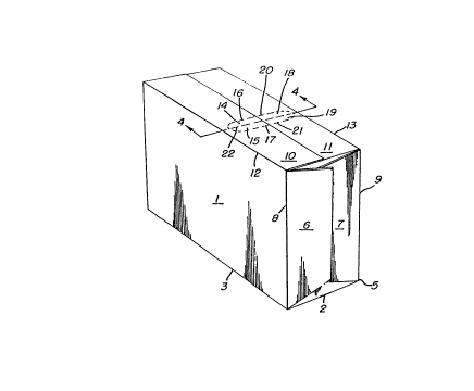
, 20 FIG. 1 is a perspective view of a set up carton
formed according to this invention;
. ~ . FIG. 2 is an enlarged exploded view showing the
', handle portion'of the carton;
FIG. 3 is an enlargsd fragmentary perspective view
~ 25 of the carton handle;
',l FIG. 4 is a sectional view taken along the li,ne 4-4
in FIG. l;
' FIG. 5 is an enlarged view o~ the carton handle as
, viewed from underneath the top wall; and
: 30 FIG. 6 is a perspective view similar to FIG. 1 and
showing a modified form of the invention.
BEST'MODE OF CARRYING OUT THE.INVENTION
With particular reference to FIG. 1, the carton
~-, comprises side wall 1 which is foldably ,joined to bottom wall
' 35 ' ' 2

~000314

D-2518

2 along fold line 3. Bottom wall 2 is fo:~dably joined to side
wall 4, identified in FIG. 2, along fold line 5. One end wall
of the carton is formed by means of end closure panels 6 and 7
which are foldably joined, respectively, to side walls l and 4
along fold lines 8 and 9. The opposite end wall is not
observable in the drawings but comprises identical structure
to that shown in connection with end closure panels 6 and 7.
The top wall of the carton is formed by means of
overlapped lap panels 10 and 11 which are foldably joined,
respectively, to the upper edges of side walls 1 and 4 along
fold lines 12 and 13.
According to this invention in one form, handle
structure is formed in the top wall of the carton in the form
of handle flaps 14 a~d 15 which are foldably joined,
respectively, to lap pane.1 10 along fold lines 16 and 17.
~l Also, handle flaps 18 and 19 are foldably joined,
respectively, to lap panel 11 along.fold lines 20 and 21. To
complete the handle structure, pçrforated transverse slit 22
extends across a portion of the carton top wall. Perforated
transverse slit 22 can ~e extended transversely of the carton
top to fold lines 12 and 13 and, if desired, a relatively
. short distance in~o side walls 1 and 4.
. According to a feature of this invention, underlying
lap panel 11 includes cutaway portion 23 which is bounded by
:' 25 inner ends 24 and 25, respectively, of handle flaps 18 and 19
-; and by transverse edges 26 and 27 of lap panel 11 which.are
. parallel with perforated transverse slit 22. Therefore, when
the carton is formed, inner ends 28 and 29 respectively, of
: handle flaps .14 and 15 are brought into an adjacent
relationship with inner ends 24 and 25, respectively, of
handle flaps 18 and 19. This structural relationship is best
shown in FIGS. 2 and 4. Without cutaway portion 23, handle
flaps 14 and 15 would overlap, respectively, handle flaps 18
and 19 in the overlapped portions of lap panels 10 and 11 in


~000314

D-2518

the completed carton thereby causing a binding of multiple
la~ers of paperboard material when the h~ndle flaps are opened
to the operating positions shown in FIG. 3.
An alternate form of this lnvention is shown in
detail in FIG. 5 and essentially includes the feature whereby
cutaway portion 23 is extended longitudinally of the carton
into adjoining portions of lap panel I1. In effect, this
causes cutaway' portion 23 to be longer than the width of
handle flaps 18 and 19.
In operation, when it is desi;red to transport the
carton, the user's fingers are simply slipped into the handle
whereby handle flaps 14, 15, 18 and 19 are folded downwardly
into generally vertical positions ' and the carton is
transported in the normal manner. The expansion of cutaway
portion 23, as shown in FIG. 5, eliminat'es a double thickness
of paperboard material adjacent transverse edges 26 and 27
'~ with the result that the handle flaps are more easily
~ maneuvered into the carrying position without engaging the
transverse edges 26 and 27 and any undesirable binding of the
paperboard material is vlrtually eli~;n~ted.
For the purpose o~ understanding another form of
carton handle :structure formed according to this invention,
, . ..
~ reference may be had to FIGS. 1-5 wherein handle flaps 14 and
.~ .
18 are foldably ~oined, respectively, to lap panels 10 and 11
along fold lines 16 and 20 with elements'17 and 21 comprising
perforated transverse slits. Likewise, the handle is also
o~erable wherein handle flaps 15 and l9 are foldably joined,
respectively, to lap panels 10 and 11 al'ong fold lines 17 and
21 and elements'16 and 20 form perforated transverse slits.
In this version of the invention, element 22 is either
incorporated into the handle structure as a fold line or can
be omitted altogether. In operatlon, the handle is
essentially manipulated in the same manner as that discussed
in connection with FIGS. 1-6.
35 ' ' 4

~00031~

D-2518


A mod~fied version of this invention is shown in
FIG. 6 wherein, instead of the overlapped panels forming the
carton top wall, they form the carton side wall. More
specifically overlapped lap panels lOa and lla form the side
wall of the carton and handle flaps 14a and 15a are foldably
joined, respectively, to lap panel lOa along fold lines 16a
and 17a. Similarly, handle flaps 18a and l9a are foldably
joined, respectively, to lap panel lla along fold lines 20a
and 21a.
INDUSTRIAL APPLICABILITY
By thls invention, the formation of the carton
handle in the overlapped lap panels or manufacturing joint of
the carton acts to increase overall carton strength in the
area of the handle. Since the handle, in essence, comprises
four handle flaps, opening of the handle is greatly
facilitated. In additlon, the g~ued manufacturing joint
adjoining the handle absorbs stress when the carton is
transported.

:


: . ,
,-.. .


~,, ' -' '
~ .


Representative Drawing
A single figure which represents the drawing illustrating the invention.
Administrative Status

For a clearer understanding of the status of the application/patent presented on this page, the site Disclaimer , as well as the definitions for Patent , Administrative Status , Maintenance Fee  and Payment History  should be consulted.

Administrative Status

Title Date
Forecasted Issue Date 1999-04-13
(22) Filed 1989-10-06
(41) Open to Public Inspection 1990-04-21
Examination Requested 1996-09-25
(45) Issued 1999-04-13
Deemed Expired 2008-10-06

Abandonment History

There is no abandonment history.

Payment History

Fee Type Anniversary Year Due Date Amount Paid Paid Date
Application Fee $0.00 1989-10-06
Registration of a document - section 124 $0.00 1990-01-29
Maintenance Fee - Application - New Act 2 1991-10-07 $100.00 1991-09-25
Maintenance Fee - Application - New Act 3 1992-10-06 $100.00 1992-08-14
Maintenance Fee - Application - New Act 4 1993-10-06 $100.00 1993-09-22
Maintenance Fee - Application - New Act 5 1994-10-06 $150.00 1994-09-06
Maintenance Fee - Application - New Act 6 1995-10-06 $150.00 1995-09-18
Maintenance Fee - Application - New Act 7 1996-10-07 $150.00 1996-09-10
Maintenance Fee - Application - New Act 8 1997-10-06 $150.00 1997-10-02
Maintenance Fee - Application - New Act 9 1998-10-06 $150.00 1998-10-05
Final Fee $300.00 1998-11-17
Maintenance Fee - Patent - New Act 10 1999-10-06 $200.00 1999-09-15
Maintenance Fee - Patent - New Act 11 2000-10-06 $200.00 2000-09-13
Maintenance Fee - Patent - New Act 12 2001-10-08 $200.00 2001-09-14
Maintenance Fee - Patent - New Act 13 2002-10-07 $200.00 2002-09-11
Maintenance Fee - Patent - New Act 14 2003-10-06 $200.00 2003-09-15
Maintenance Fee - Patent - New Act 15 2004-10-06 $450.00 2004-09-15
Maintenance Fee - Patent - New Act 16 2005-10-06 $450.00 2005-09-21
Maintenance Fee - Patent - New Act 17 2006-10-06 $450.00 2006-09-18
Owners on Record

Note: Records showing the ownership history in alphabetical order.

Current Owners on Record
MEADWESTVACO PACKAGING SYSTEMS LLC
Past Owners on Record
MARQUIS, HAROLD L.
THE MEAD CORPORATION
Past Owners that do not appear in the "Owners on Record" listing will appear in other documentation within the application.
Documents

To view selected files, please enter reCAPTCHA code :


To view images, click a link in the Document Description column. To download the documents, select one or more checkboxes in the first column and then click the "Download Selected in PDF format (Zip Archive)" or the "Download Selected as Single PDF" button.

List of published and non-published patent-specific documents on the CPD .

If you have any difficulty accessing content, you can call the Client Service Centre at 1-866-997-1936 or send them an e-mail at CIPO Client Service Centre.


Document
Description 
Date
(yyyy-mm-dd) 
Number of pages   Size of Image (KB) 
Abstract 1994-01-22 1 15
Cover Page 1994-01-22 1 16
Claims 1994-01-22 2 85
Drawings 1994-01-22 2 45
Description 1994-01-22 4 172
Cover Page 1999-04-07 1 34
Representative Drawing 1999-04-07 1 8
Fees 1998-10-05 1 38
Prosecution-Amendment 1998-11-12 1 38
Correspondence 1998-11-17 1 36
Assignment 2003-12-31 11 512
Correspondence 2004-02-04 2 3
Fees 1997-10-02 1 34
Assignment 2004-03-26 1 48
Prosecution Correspondence 1996-09-25 2 58
Office Letter 1996-10-22 1 52
Fees 1991-09-25 1 30
Fees 1992-08-14 1 27
Fees 1993-09-22 1 31
Fees 1994-09-06 1 29
Fees 1995-09-18 1 38
Fees 1996-09-10 1 34