Note: Descriptions are shown in the official language in which they were submitted.
- 200 1 020 ,
BATI~RY HOUSING WmI XNTEGRAL LATCH AND
POSITIVE DISPLACEMENT APPARATUS
BackFrolmd of the Invention
T}li8 invention relates generslly to bat~ery bousing
apparatus and more particularly to an intsgral battery
10 housing assembly which has an integral latching mechanism
and integral spring fingers to provide positive displacement of
the battery when the latch mechanism iB disengaged. This
invention is related to Canadian Patent No. 1,292,514
filed on behalf of Michael W. Zurek et al.
Miniature electronic equipment i9 often portaUe in
nature and, as such, require~ a portable source of power such
as a battery. A battery ~upply may be conveniently attached to
the housing of the miniature electronic equipment and make
20 electrical contact by way of a conventional connector. To make
battery char~png easier, mechanisms have been devised to
enable the user to easily disconnect a spent battery and replace
it with a freshly charged battery. It has been proven desirable
to securely affix the detachable battery to the miniature
25 elPctronic equipment by way of some ~ort of latching
mechanism. As the equipment becomes smaller, however,
volume within the miniature electronic equipment cannot be
afforded for e~tensive latching mechanisms. Thu8, it would
be advantageous for latching mechanisms to be placed in
30 locations other than within the miniature electronic
equipment.
~.-`' ' ;: . `
.
Z~ O
OE~F~.
Summary 9f ~e Invention
It is, therefore, one object of the present invention to
provide a battery housing utilizin~ an integral latch
5 mechanism.
It i8 another object of the present invention to utilize
cantilevered spring fingers integral to the battery housing to
provide a po~itive displacement of the battery when the latch is
disengaged.
It is a further object of the present invention to minimize
binding of the battery housing during installation and
disengsgement.
Accordingly, these and other objects are realized in the
present invention which encompasses a unique batte~r
housing having integral latch and positive displacement
spring fingers to enable easy installation and removal of the
battery.
Brief I)escIi~tion ~h~
Figure 1 is an isometric drawing of a hand-held portable
radiotslephone which may employ the present invention.
Figures 2A and 2B are drawings of a battery housing
(Fig. 2A) and portable radiotelephone (Fig. 2B) in which the
battery has been detached from the portable radiotelephone.
Eigure 3 is a view of the mating surface of the battery of
Fig. 2A shQwing the integral latch, positive displacement,
cantilevered spring fingers, and reduced travel gwde rails of
the present inven~on.
Figure 4 is an exploded view of the battery of Fig. 2A.
Figure 5 i~ a view of the cantilevered spring fingers
which may be used in the battery housing of Fig. 2A.
.
.
- 2~01(~Z0
,
CE0008~
Figure 6 is an isometric ~iew of the latch mechanism of
the battery housing of Fig. 3.
I)etailed l:)escli~tion of the Preferred Er~abQ~m~
A portable radiotelephone adapted to be used in a
cellular radiotelephone system is shown in Fig. 1. The
present invention may be employed in such a portable
radiotelephone as well as in other miniature electronic
10 equipment. The illustrated portable unit consists of two
external portion3, a body portion 102 and a flip element portion
104, in addition to a detachable battery 105. The drawing of
Fig. 1 shows the flip element 104 in an "open" position such
that a user of the portable unit may listen via earpiece 106
15 and may speak into a microphone 107. A telephone dial, or
-keypad, 110 consists of a plurality of buttons numbered one
through zero, #, and *, in a familiar telephone arrangement.
The keypad 110 also has additional function buttons such as
"send", "end", "on/ofP', and other buttons associated with
20 telephone number recall.
Since the portable radiotelephone of Fig. 1 is indeed
portable, some source of electrical energy is necessary to
power the electrical functions of this radiotelephone. The
source of this electrical energy is a battery 10~ which is
25 typically implemented as a rechargeable electrochemical cell
or ce~ls. It is expected that the user will be aUe to either
recharge the battery while the battery is attached to the radio
or detach the battery from the radio and charge it separately.
RefelTing now to Fig. 2A, the configuration of the
30 detachable battery 105 can be apprehended in the condition
where the batte~r 105 is detached from the portable
radiotelephone of Fig. 1. An integral latch mechanism 201 is
~ . . .
.~ . .
. ~ '
: ~ - -
.. -
.
z~
-
C~.
integrally molded on the batte~ housing. (In the preferred
embodiment of the present inventinn, the battery housing
consists of two halves which are permanently affixed together.
The latch mechanism iB molded into the inside half of the
5 plastic housing). To disengage the battery 106 from the
portable radiotelephone 102, the latch mechanism 201 is
pushed at the portion visible in Fig 2A thereby causing a
torsion beam (not shown) to rotate and cause a catch (not
shown) to retract form a pocket 212 in the portable
10 radiotelephone 102. (The portable radiotelephone 102, in a
rear elevation view with the battery removed, is ~hown in Fig.
2B). This action releases the battery from its locked position
and enables the batte~y housing 105 to be removed form the
portable radiotelephone 102. The mating surface of the
15 portable radiotelephone 102 has a pocket or indented slot 212
which is 80 formed and positioned that it engages the catch
portion of latch mechanism 201 when the battery housing 105
is located in ita fully attached position. The battery housing is
thereby locked in place. Guide rails 213 through 218 extend
20 from a ~urface of the portable radiotelephone housing 102 and
are disposed opposite similar g ude rails on the battery
housing 105. The guide rails of the battery housing 105 are
captivated beneath guide rails 213 through 218 ofthe portable
radiotelephone housing 102 when the battery housing 105 is in
25 its operational (and locJ~ed) position. The operational position
is, of course, when electrical contacts 225 have contacted
mating contacts 325 (not visible) of the battery housing 105.
Also visible ~ Fig. 2B are two molded flanges 220 and 221
which provide surfaces useable for preloading cantilevered
30 springs enabling positive displacement of the battery housing
105 when it is unlocked.
.
-:
2~ iZO
OE~
Lateral slots 233 and 235 in Fig. 2A on opposite sides of
the battery housing assembly 105 are located in a position such
that the battery alone or the batter,y and portable
radiotelephone together may slide into a common battery
charging unit and be properly orie~ted relative to the battery
charging contacts 239.
The surface of the battery hou~ing 105 which mates to
the portable radiotelephone of Fig. 2B is shown in the elevation
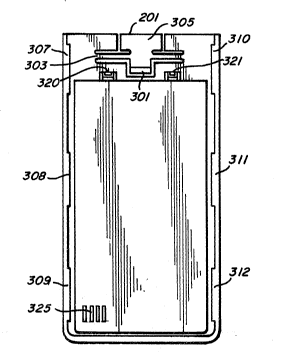
view of the mating surface of Fig. 3. Tbe latch mechanism 201
1 0 is seen in greater detail and it can be perceived how the catch
301 rotates about the torsion bar 303 when the button portion
305 is pressed by the user to remove the battery. An isometric
view of the latch mechanism is shown in Fig. 6. Such a button
pressing in a direction out of the plane of the page of Fig, 3
1 5 (and into indented area 227 of the portable radiotelephone
housing 102) causes torsion bar 303 to rotate and move catch
301 into the plane of the page of Fig. 3. This motion
disengages the catch 301 from slot 212 (shown in Fig. 2B)
thereby unlocking the batte~r housing and enabling the user
to slide the battery along guide rails 307 through 312. Once
guide rails 307 through 312 have moved past the opposing
guide rails 213 through 218 on the portable radiotelephone
housing 102, the battery 105 may be lifted clear of the portable
radiotelephone 102.
To aid in battery removal, cantilevered spring fingers
mechanica~ly load the battery when the battery is in the
inserted and loc3~ed position. Refemng again to Fig. 3, two
spring fingers in the prefe~ed embodiment are shown as
spring fing~rs 320 and 321. When the battery is in place,
spring fingers 320 and 321 on the battery housing are deflected
downward by tabs 220 and 221 located on the portable
radiotelephone housing 102. This dowrlward deflection of
~-~' ~ - , .,
,
2~01~'20
OE~X~083R
spring fingers 320 and 321 provide a po~itive displacement of
the battery when the latch mechanism 201 is activated by the
user. The battery, therefore, begins its disengagement when
the user presses the latch mechanism and the battery slides
5 downward enabling guide rails 307 through 312 to partially
disengage from guide rails 213 through 218 on the portable
radiotelephone housing. The guide rails are formed from
raised protuberances on the inside surfaces of the lip edgex
which are raised slightly above the battery housing surface
10 which faces the portable radiotelephone. When g~ude rails 307
through 312 are fully disengaged ~rom the portable
radiotelephone housing, the battery electrical contacts 325 are
disengaged from the battery input electrical contacts 22~ on
the portable radiotelephone housing.
15An exploded sectional view of the battery housing is
shown in Fig. 4. In this diagram it can be seen that a
conventional set of electrochemical batte~ cells 401 may be
sandwiched between and captivated by two plastic housing
portions 403 and 405 which may be secured together to form an
20 integral batte~ housing package. It should be noted that the
latch mechanism 201 is molded as part of the plastic portion
405 and the cantilevered spring fingers 320 and 321 are molded
as part of plastic portion 403 to minimize cost and reduce the
volume required to implement the latching and positive
25 di~placement features of the present inven~ion. In the
preferred embodiment, three guide rails 310, 311 and 312 are
located on one side of the battery housing and three guide rails
(307, 308 and 309 not shown) are located on the other side of the
battery housing. These shor$ened guide rails with gaps in
30 bet veen each enable secure fasteI~ing of the battery housing
105 to the portable radiotelephone housing 102 the entire
- length of the batte~ housing 10~ while allowing a short travel
- .
2~.01(iZ0
displacement of the battery housing before the battery housing
may be disengaged and removed firom the portable
radiotelephone 102.
Figure 5 shows a cross-section of housing portion 403
5 which more clearly show6 the spring fingers 320 and 321 as
well as guide rails 310 and 307. It can be seen that lip edges
501 and 503, on opposite sides of the battery housing, are
raised slight;ly above the plane of the surface of the battery
housing which mates with the portable radiotelephone. In the
1 0 cross-section shown in Fig. 5, the protuberances which form
guide rails 310 and 307 are visible on the in~ide surface of the
raised lips 501 and ~03 respectively. In the preferred
embodiment, each spring finger is a cantilevered trapezoidal
shaped beam emanating at one end from the housing portion
1 ~ 403 and ending at the opposite end with a rectangular shaped
target area 501 or 503 each of which contacts the flanges 220
or 221 of the portable radiotelephone housing. Also in the
preferred embodiment, the housing portion 403 is molded
from polycarbonate plastic or similar material and each
20 spring finger i~ 0.13cm thick, and having a width at the point
of attachment to the housing portion 403 of 0.51cm and
narrowing to a target area of 0.13cm. The length of the apring
finger is 0.69cm from the point of attachment to the beginning
of the rectangular target area. Each spring finger provides
25 0.85 Kg of preload to the battery housing relative to 1 he portable
radiotelephone housing.
In summa~y, then, a battery assembly ha. ing an
integral latch mechanism, cantilevered spring fingers to
provide positive displacement when the latch is disengaged,
30 and reduced travel guide rails to provide short travel between
the engaged and disengaged position of the battery housing on
a portable radiotelephone has been shown and described.
.
. .
-: :
Z~01(3Z0
OE00083R
While a particular showing and description i8 contained
herein, it iB to be understood that the invention is not to be
taken as limited to the specific embodiment herein and that
changes and modifications may be made without departing
from the true spirit of the invention. It is therefore
contemplated to cover the present invention, and any and all
such changes and modifications, by the appended claims.
We claim:
. ~
,
, .