Note: Descriptions are shown in the official language in which they were submitted.
;Z(lO11127
CLOCK OR WATCH
TECHNICAL FIELD
The invention relates to a timepiece, in particular to a
watch or clock having a distinctive three dimensional face.
BACKGROUND ART
Various ornamental watches have been developed whereby
the face of the watch has an artistic quality. Typical
1~ examples of such watches or watch faces can be found in U.S.
Pat. Nos. 140,234 (clock dial); 151,204 (watch dial) and
282,723 (clock). With the exception of the last reference, all
of these and many other ornamental watches rely on numerals or
at least one other indicia to assist in time telling.
None of these prior art timepieces exhibit the three
dimensional qualities of the invention and are capable of
clearly and accurately indicating time solely by the
construction of their faces.
SUMMARY OR THE INVENTION
The present invention relates to an apparatus for
indicating time comprising a face having members arranged in a
predetermined pattern around a central point thereby forming a
25 continuous surface and means for determining elapsed time. The
members may be arranged to represent predetermined time
intervals, preferably twelve members each representing a five
minute interval. Hands which rotate around the face relative
to the members may be used as the time determining means.
30 Means for sequentially illuminating the members or a
combination of hands and illumination means may similarly be
used.
The face and time determining means may be protected from
external sources by use of a crystal which is configured to
35 securely attach to said face. Also, the invention may be
2nolQz7
- 2 -
supplied with means for attachment to a support member. Such
means may include a pair or posts for mounting a watchband or,
a hook or recess for securing the invention to a wall or other
surface.
The interior pattern of the watch may vary such that the
member of the face converge to the central point or terminate,
prior to intersection at the central point, to form a closed
area. Similarly, the perimeter of the face may have several
configurations. For example the perimeter may be substantially
10 circular, rectangular, or rectangular with rounded edges.
BRIEF DESCXIPTION OF THE DRAWINGS
Further benefits and advantages of the invention will and
15 become apparent from a consideration of the following
description given with reference to the accompanying drawing
figures which specify and show preferred embodiments of the
invention, and wherein:
FIG. 1 is perspective view of a watch having a face
20 according to the invention with a circular perimeter;
FIG. 2 is a front view of the watch of FIG. 1;
FIG. 3 is a side view of the watch of FIG. l;
FIG. 4 is a front view of a clock having a face according
to the invention with a substantially rectangular perimeter;
FIG. 5 is a front view of a clock having another face
according to the invention this time having a circular
perimeter and a serrated pattern; - -
FIG. 6 is a front view of a clock illustrating yet
another embodiment of the invention featuring a face having
30 stepped perimeter;
FIG. 7 is a front view of a clock demonstrating a further
embodiment of the invention featuring a face having perimeter
of a twelve pointed star;
FIG. 8 ls a front view of a clock similar to that of FIG.
35 7 but having an internal flat circular shape.
,,: . ., : .
- . : ~ .: . ,
. .
:
, ~ ,. . . .. .
, . , . : ~ .,
2()01(~Z~
- 3 -
,
FIG. 9 is a front view of a clock similar to that of FIG.
8 but having a different internal shape.
DETAILED DESCRIPTION OF THE P~EFERRED EMBODIMENTS
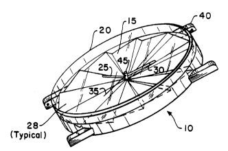
Referring now to FIGS. 1-3 there is illustrated an
apparatus for indicating time substantially in the form of a
watch l0 comprising a circular face 15, matching crystal 20,
hour hand 25, minute hand 30, second hand 35, central portion
or stem 45 and pair of posts 40 for attaching a watchband.
10 Although the invention is described with respect to a
wristwatch, other forms of timepieces are included in this
inventi~,n, such as pendants, clocks, timers~sundials, and the
like.
r,.'he circular face 15 of the watch l0 includes a plurality
15 of me~ers 28 (typical), which are tilted at an angle with
respect to a horizontal plane and which are joined around a
central point in a cascading or stepped relationship to form a
continuous surface. In the most preferred embodiment, twelve
members are arranged such that each member represents a five
20 minute interval, however this is not critical to the design.
For example, time intervals of numerical divisions of 60 (i.e.,
2 to 60) are possible without departing from the invention.
Generally, a lower even number of members, such as 2, 4, 6, or
12, is preferred.
The face 15 has a perimeter 33 which is comprised of the
individual peripheries of the members and may vary greatly in
terms of size and shape. The size of the perimeter will be
determined by the intended use of the invention, for example, a
wristwatch will have a perimeter which is substantially smaller
30 than that of a wall clock. On the other hand, there is an
endless assortment of shape6 which can be constructed by
varying the number of members and their respective peripheries,
the selection of which are generally a matter of artistic
preference. As illustrated in the drawings, 12 members has
35 been found to be the most advantageous at this time.
Z()(11(~27
,
Each member of the face 15 includes a first plane 60 and
a second plane 65 which are substantially perpendicular to one
anot~er and intersect to form a common edge 50. To form the
surface of the face 15, the ~econd plane of one member
5 intersects the first plane of an adjoining member to form a
common edge 55. These edges define the boundaries of the
planes, which in turn comprise the stepped feature of the watch
face. Each step defines the difference in height between the
first plane of one member an~ the first plane of an adjoining
10 member at any point along the radial boundary therebetween.
Subsequently, each step has a substantially triangular shape
which is a function of the radial distance from the central
portion or stem 45 along the boundaries, the angle of the first
plane of a member with respect to the horizontal, the angle of
5 the second plane with respect to the first and the number of
time intervals represented. Accordingly, each of these -
parameters may be varied, within reason and with respect to the
intended use of the invention, to enhance the visual and
aesthetic qualities of the steps formed thereby.
In this respect, the angle which the first plane 60 forms
may vary from ten to sixty degrees with respect to the
horizontal, however, the preferred angle ranges from ten to
thirty degrees. In add$tion, the angle which the second plane
65 forms with respect to the first may be varied either to
25 maintain perpendicularity with it as it varies or independently
thereof to approach the vertical plane. Depending upon the
angle which the second plane forms with respect to the first,
the boundaries of the step formed thereby may either appear as
two angled lines converging toward the central point or, in the
30 case where the ~econd plane i8 vertical, as one single iine,
when viewed from above. Once again, the angle between the two
planes of a member and the subsequent for~ation of the steps
thereby are not critical to the functional design but are a
matter of artistic preference. However, the variation in the
35 size of the perimeter of the face 15 and the number of time -
- - . - . .
:
: ' , ' ` :,
'~
2()0111 ~7
- 5 -
intervals, which also determine the size and shape of the
steps, are intrinsic to the funct:ional purpose of the invention
and depend on its intended use. For example, a wristwatch has
a limit as to its size and, therefore, the number of time
5 intervals which may reasonably be employed.
The steps formed by the intersection of the planes
converge from the periphery of the respective members toward
the central portion or 6tem 45. In this illustration, these
steps converge to the central portion, however, this is not
10 essential to the design. For example, these steps may
terminate at predetermined distances from the central portion
to define a closed area, such as a circle, a rectangle or any
other shape to further enhance the aesthetic value of the
watch. The enclosed area also may be used to include other
15 functions, such as day, date, calendar, calculator or the like.
The crystal 20, which may be made of transparent plastic
or glass or other well known materials, is attached to the face
15 of the watch 10 to protect the hands and the surface of the
face from external sources. The perimeter of the crystal 20
20 corresponds to that of the face 15 in size and shape and the
bottom or base of its periphery is provided with a saw-toothed
design. This design is coordinated with the stepped
configuration of the face, therefore comprising a mating
surface for gluing. Press fitting or other means of fastening
25 the crystal may also be employed and, in some cases, for clock
design, for example, the crystal may be omitted.
Situated between the upper surface of the face 15 and the
bottom surface of the crystal 20 are the hour 25, minute 30 and
second 35 hands. These hands are ~ecurely attached to a stem
30 45 and are driven by any suitable clock mechanism such that
they rotate around the face 15 relative to the me~bers. The
position o~ these hands, at any instant, relative to the
members and the orientation of the face will indicate time.
2~ 7
While hands are shown on the drawing as the preferred
method of indicating time, it may be seen that other time
indicating means are available for example, the invention may
be proYided with at least one hand and a light for sequentially
5 illuminating the members. In this embodiment, the illuminated
member(s) would represent the present hour, while the hand
would move relative to the members to indicate the minute.
Other combinations of hands and illumination means may also be
used. For example, a portion of the member, such as a circle
10 or square ornament placed near the end, could be illuminated to
designate the hour.
In addition to hands or illuminating means, numerals or
other indicia may be incorporated on the face to assist in
deciphering the time. Such indicia would include jewels,
15 posts, circles, hemisphere, rectangles, triangles, etc., placed
at a conspicuous location generally near the o~ter periphery of
each or most of the members 28. While such symbols may
increase the ease of telling time, they may also detract from
the aesthetic simplicity of the current design.
The invention also has a pair of posts 40 provided
opposite to one another along the perimeter of the face to
allow for the attachment of a watchband. Further, instead of
the posts or, in addition to them, the invention may be
equipped with other means of support depending upon the
25 intended use as a wall clock or pendant, for example.
It may also be seen that a wide variety of colors and
materials are available for use in the manufacturing of the
face 15 and hands. For example, the face may be manufactured
out of a transparent material to allow the internal mechanism
30 of the watch to be viewed. A translucent material could be
used where the members 28 are to be illuminated. Or, the
hands, numbers, or portions thereof, may be coated with a
luminous material allowing them to be read in the dark. The
selection of color and material is a matter of artistic
35 preference and is not critical to the invention.
- . - . - ~ . .
,
. - .
.
200~2'7
-- 7 --
Another application of this invention is a specific
embodiment for use by the blind or visually impaired. In such
an embodiment, either the crystal 20 is omitted or it is
attached to the face with a hinge so that it may be rotated
5 away from the face 15. Either configuration will allow access
to the members which will be configured so that they are
readily discernible by touch. Also, the watch will be provided
with at least one raised indicia for orientation of the face,
e.g., to designate the ~o~clock" position. To decipher time by
10 the sense of touch, the fingers will travel about the face 15
to locate the hands, the corresponding members and their
position relative to the raised reference indicia.
FIGS. 4-8 illustrate the invention in the form of a
clock. Although no cover or crystal is shown, it is clear that
15 such can also be used, if desired.
FIG. 4 illustrates an embodiment comprising a face 70
whose perimeter is substantially rectangular. The corners 80
of this rectangular may either be rounded, as ~hown, or square.
Also, in this illustration, the second plane 65 of each member
20 is substantially vertical in which case the edges 50 and 55
appear as one line when viewed from above. The angle of the
second plane with respect to the first plane is not critical
and can vary over a wide range.
FIG. 5 demonstrates an embodi~ent in which the boundary
25 of t~e first plane of each member forms a shape which is
substantially triangular 90 and in which the perimeter of the
face 85 is circular. The radius of the circle is defined as
the farthest point from the center along the boundary of the
first plane.
FIG. 6 illustrates an additional embodiment of a clock
according to the invention, wherein the periphery of each
member offers a slightly different variation on a common
pattern which features a series of incremental ~teps. The
perimeter of the face lO0 formed by these members i8
35 substantially circular. In this embodiment, due to the
~; '
. .
2()(~
-- 8
irregular perimeter, the crystal would either be omitted or
employed to cover only a portion of the face without making an
attempt to duplicate the perimeter.
FIG. 7 depicts a series of rectangular members arranged
5 in a stepped configuration about the center point. The
resulting perimeter of the face 110 is a twelve pointed star
shape. Again, it may be advantageous to omit the crystal llS
or to make use of a crystal which covers only a portion of the
face.
FIG. 8 exhibits an alternative embodiment to the clock of
FIG. 7. The edges 50 and 55 of the members 28 converge toward
the central portion 45 but terminate at predetermined distances
from said point thereby comprising a closed area 120 in the
form of a circle. This alternative design may bs applied to
15 any of the previously mentioned embodiments and may take any
form selected by the manufacturer.
While it is apparent that the invention herein disclosed
is well calculated to fulfill the objects above stated, it will
be appreciated that numerous modifications and embodiments may
20 be devised by those skilled in the art, and it is intended that
the appended claims cover all such modifications and -~
embodiments as fall within the true spirit and scope of the
present invention.
,, . :
.
.
- ' ' . , . ':
- : :