Note: Descriptions are shown in the official language in which they were submitted.
---` 20010~9
The present invention relates to an oil filter to be
incorporated in a l~bricating system for an internal
combustion engine or the like and, more particularly, to an
oil filter of a type in which not only solid contaminants but
also gaseous contaminants can be removed from the oil.
In machinery for construction, transportation and the
like using lubricant, such as engines and various hydraulic
devices, solid contaminants and gaseous contaminants have
hitherto been removed from lubricant by separate devices
and/or in different portions of the machinery. A device has
thus been desired which can remove both of the solid and
gaseous contaminants effectively and which can be installed
in a limited space of the machinery.
The inventors herein have proposed an integrated device.
The device comprises a first separator having a filter
element for filtering lubricant which is pumped into a
housing to thereby remove solid contaminants, and a second
separator for removing gaseous contaminants from the
- 1 -
1~ -
~ . ' ' `':. "
1~. ! ' `
' ` ` ` ` ~ ' " ``'`'~'`, ~
: ' `' ''~ '`' ` ": ''`' `
2~10~L9
~iltered oil by utilizing a centrifugal force.
Specifically, the second separator has a chamber adapted
to generate a vortical flow of the lu~ricant introduced
therein, whereby the lubricant having little geseous
contaminants and therefore having a larger specific
gravity gathers in a peripheral area of the chamber while
gas-rich lubricant having a smaller specific gravity
gathers in a central area. A wall defining the chamber is
provided with a plurality of pores through which the gas-
removed lubricant flows out of the chamber. On the other
hand, the gas-rich lubricant is discharged by a perforated
pipe which extends into the chamber;along its axis.
In the above proposed device, both the first and
second separators are arranged within a housing which is
to be attached to a mount block in a lubricating system.
The mount block should in turn be provided with various
passages to supply the lubricant into the housing, lead
the filtered and gas-removed lubricant to various parts to
be lubricated, and to discharge the gas-rich lubricant
into a tank or recirculation, and attachment of the
housing involves connecting these passages to respective
portions of the. housing. However, the above device is not
so constructed that it may easily be attached to the
mount, and relatively complicated work will be needed for
the attachment. This is particularly important because,
as is well known in the art, the filter element is
subjected to replacement due to its clogging during a use
` `' ` `'
~` ~ ' ~' . '
,: ~
.~ . .
20010~9
of the device.
~ or a conventional type oil filter adapted to remove
only the solid contaminants, it is an usual practice to
replace the oil filter as a whole, i.e. including a housing.
Although such a practice has been found desirable,
application thereof to the above proposed device would be a
waste of the second separator which can be used semi-
permanently. Further, there are many replacement units of
the conventional oil filter available in the market, but
those units can not be used for the above proposed device.
.
The invention provides an oil filter which can
efficiently remove both solid and gaseous contaminants from
the oil and which can easily be assembled and then
incorporated in a lubricating system.
The invention also provides an oil filter in which a
filter element for removing solid contaminants can be
replaced without complicated work and without a necessity of
replacing an entire device.
Further, the invention provides an oil filter which
enables to use a replacement unit of usual type.
The present invention utilizes a mount block in a
lubricating system. Thus, an oil filter of the invention
-- 3
Bii .
,
)49
comprises a housin~ opened at one end thereof, a first
separator unit disposed in the housing for removing solid
contaminants from the oil introduced into the housing, a
mount block to which the housing is attached, and a second
separator unit arranged in the mount block for removing
gaseous contaminants from the oil that has passed through
the first separator unit. The first sQparator unit
includes a cylindrical filter element having an inner
periphery and a central space defined within the inner
periphery. Formed in the mount block is a recess in which
the second separator unit is dispoced, and an inlet
passage for supplying the oil into the housing. The
second separator unit includes a chamber adapted to
generate a vortical flow of the oil introduced therein to
thereby separate gas-rich oil which gathers in an axially
central portion of the chamber, means for introducing the
oil from the central opening of first separator unit to
the chamber, a first outlet means for leading the oil
containing little gaseous contaminants outside the mount
block and a second outlet means for discharging the gas-
rich oil outside the mount block.
In a preferred embodiment of the invention, the
second separator unit further includes a cyclone secured
in the recess to define the chamber and having a plurality
of pores formed through the wall thereof. The first
outlet means comprises the pores, the recess and a first
outlet passage extending in the mount block and opening in
,:
~: .
200~ 0~9
the recess. The second outlet means may comprise a removal
pipe extending into the chamber along the axis of cyclone and
having formed in the wall thereof a plurality of orifices for
permitting the gas-rich oil to flow thereinto, and a second
outlet passage in the mount block to communicate with the
removal pipe.
The invention will be more apparent from the following
description of the preferred embodiments thereof when taken
in conjunction with the accompanying drawings.
FIG. 1 is a longitudinally sectioned elevational view
illustrating an oil filter according to an embodiment of the
invention; and
FIG. 2 is a view similar to FIG. 1 illustrating an oil
filter according to another embodiment of the invention.
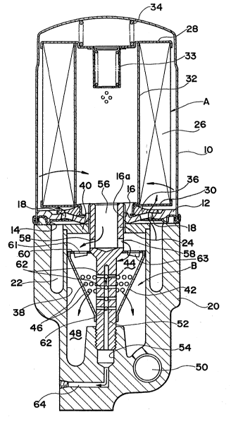
Referring first to FIG. 1 of the drawings, an oil filter
according to a first embodiment of the invention has a
housing 10 of substantially cylindrical shape having a lower
open end and an upper closed end. A base plate or disk 12 is
secured to an inner peripheral surface of the housing 10 at a
position near its lower end and is fixedly supported by means
of a ring member 14 of which outer edge is seamed with the
lower edge of the housing 10. The base plate 12 is formed
with a central opening defined by an upwardly projecting
circular wall 16 which has a threaded
- 5 -
.,.';~ .
.. .
2~ 049
inner surface 16a. An aperture 18 is provided in the base
plate 12 radially outward of the opening, communicating
with an inlet passage 22 formed in a mount block 20 to
which the base plate 12 and therefore the housing 10 are
attached. The mount block 20 is provided with a
separately formed sleeve 24 which extends into the opening
of the base plate 12 to threadedly engage with the inner
surface 16a of circular wall 16. The ring member 14 is
provided with a depression which is in tight contact with
the upper surface of mount block 20 at a position radially
outward the inlet passage 22 for preventing leakage of an
oil.
Arranged within the housing 10 are a separator unit
A for separating solid contaminants from the oil
circulating in a lubricating system of a machine. The
separator unit A is of usual type and comprises a filter
element 26, an upper and plate 28 and a lower end plate 30
both fixed to the element 26. The filter element 26 has a
hollow cylindrical shape and is typically formed of a
pleated sheet. A perforated plate 32 is attached to the
inner periphery of element 26 in order to prevent the
element from collapsing while allowing the oil to flow
into the central space within the unit A. The upper end
plate 28 extends radially inward to support a relief valve
33 and a spring 34 which is compressed between the top
wall of housing 10 and the upper end pla~e 28, thereby
holding the unit A in position. The relief valve 33 is
.. ~ , ,.
.,
: . '
2~)V~9
adapted to open and provide a bypass passage for the oil
when a pressure of oil is increased outside the filter
element 26 due to a clogging thereof, 80 ~hat the oil can
flow through the valve 33 into the space defined within
the element 26. On the other hand, the lower end plate 30
extends shightly beyond the perforated plate 32 where it
is bent downwardly to secure a check valve 36 that is
adapted to prevent a reverse flow of the oil from the
housing 10 into the inlet passage 22.
A second separation unit B is provided in the mount
block 20 for removing gaseous contaminants from the oil
that has passed through the first unit A. The second
separator unit B includes a recess 38 which is formed in
the center portion of mount block 20 and is closed by a
cover plate 40 the upper surface of cover plate 40 being
flùsh with the upper surface of mount block 20. The cover
plate 40 has an opening through which the sleeve 24
extends into the housing 10. A funnel-shaped cyclone 42
is disposed in the recess 38 and is fixed at its upper
edge to the wall defining the recess in a liquid-tight
manner. The cyclone 42 defines in cooperation with a
bottom plate 60 fixed thereto a chamber 44 adapted to
generate a vortical flow of the oil introduced therein .
from inlets 61 formed in the bottom plate 60. The inlet
61 is formed by punch press with providing a guide wall or
deflector 63 which extends in the circumferential ~ .
direotion of the bottom plate 60 so that the oil can flow -~
_ 7 _
. :. ~:
' :, ~'. .. .
-'
.'
2~049
into the chamber 44 with a vortical pattern. A plurality
of pores 46 are formed through the wall of cyclone 4Z to
connect the chamber 44 with a space 48 which is de~ined
between the cyclone 42 and the wall of recess 38 and
communicates with a first outlet passage 50 e~tending in
the mount block 20.
A removal pipe 52, which is an extension of the
sleeve 24 with a reduced diameter, extends in the chamber
44 along its axial center to project downwardly through
the lower open end of cyclone 42 that is closed by the
pipe 52. The lower end of pipe 52 is threadedly fitted in
a hole 54 formed in the mount block~20, thereby securing
the base plate 12 to the block 20. The sleeve 24 has
formed therein a vertical hole 56 opening into the space
within the unit A and outlets 58 formed through the wall
of sleeve at positions adjacent the lower end of vertical
hole 56 and slightly above the upper edge of the cyclone
42. The upper portion of pipe 52 in the chamber 44 is
formed with small orifices 62 through which a gas-rich oil
flows into the pipe 52 as described later. The pipe 52 is
connected via the blank space of hole 54 to a second
outlet passage 64 which extends in the mount block 20 and
is connected to, for example, an oil pan (not shown) for
storing the oil. On the other hand, the first outlet
passage 50 is connected to, for example, an engine (not
shown) to be lubricated.
When the oil is supplied by a pump (not shown) via
': -- ' ~ ' ' '' ' ' . ' ' ' ' ' ' ' . "
`: :
2~ 0~9
the inlet passage 22, it flows into the housing 10 through
the aperture 18 and the check valve 36. The oil then
passes through the filter element 26 from outside to
inside during which solid contaminants are removed from
the oil. The thus filtered oil flows in the space within
the perforated plate 32 and is introduced into the chamber
44 via the vertical hole 56 and outlets 58, the deflector
60 inducing the vortical flow. The oil flows downward in
the chamber 44 with the vortical pattern, generating a
centrifugal force which acts on the oil. Due to a
difference in density, the oil containing geseous
contaminants, i.e. gas-rich oil, is~separated and gathers
near the axial center of the flow where it is introduced
through the orifices 62 into the removal pipe 52 for
discharge into the oil pan via the second outlet passage
64. On the other hand, the remaining oil, which contains
little geseous contaminants, flows around the wall of
cyclone 42 and passes through the pores 46 into the space
48 for circulation in the lubricating system via the first
outlet passage 50.
In this way, solid and gaseous contaminants can
efficiently be separated and removed from the oil. When
it becomes necessary to replace the ~ilter element 26 for
removing solid contaminants with a new element due to
clogging after a long use, the housing 10 is rotated
relative to the mount block 20 whereby the circular wall
16 of base plate 12 is released from the engagement with
' ~
oss
the sleeve 24. Thus, the housing 10 together with the
separation unit A can be detached from the mount block 20
which retains the separatlon unit B. Thereafter, only the
filter element 26 on the assembly of the housing 10,
element 26 and base plate 12 can be replaced. If the
latter is desired, usual type oil filter, that is
available in the market, may be used without modification.
There has been known and available in the market an
oil filter of a so-called center bolt type in which a
center bolt extends axially through the housing for
attaching it to the mount block. Onè embodiment of the
invention as applied to the oil filter of such a type is
illustrated in FIG.2 in which those parts same as or
corresponding to the parts in FIG.1 are designated by the
same reference numeral but with an addition of "100".
A housing 110 accommodating the first separation
unit A rests on the peripheral edge of upper surface of a
mount block 120 with interposing a gasket in the form of
an O-ring 166 therebetween. The housing 110 is attached
to the block 120 by means of a center bolt 168 which
extends along a center axis of the housing and is
threadedly engaged at its lower end with a hole 154 in the
block 120. The upper end of center bolt 168 fitted in a
gasket 184 penetrates the top wall of the housing 110 to
provide an enlarged head 170 for fastening or loosening
the bolt 168.
- As in the above embodiment, the unit A for
.
..... :.
,,~
- ` 2~ 0~9
separating solid contaminants comprises a filter element
126 and upper and lower end plates 128, 130. A gas~et 186
is tightly fitted between the center bolt 212 and the
lower end plate 128. Provided around the bolt 168 is a
spring 134 which is compressed between the gaskets 184 and
186 for urging the unit A downwardly, whereby the lower
end plate 130 abuts through a sealing member 188 against
an end surface of a circular flange 172 to separate an
inlet passage 122 from a recess 138. A funnel-shaped
cyclone 142 is disposed within the recess 138 and fixed at
its upper vertical edge to the inner surface of flange
1~2. The upper open end of cyclone`142 is closed by a
dish-shaped cover member 174 which has a central opening
for the center bolt 168 with an 0-ring seal 1~6 fitted
around the bolt and an aperture 178 formed through the
bottom wall of cover member ad~acent its outer end.
Integrally provided with the cover member 1~4 is a
circular wall 180 extending downwardly from the bottom
wall adjacent the aperture 178 to the slant surface of
cyclone .142, defining a chamber lg4 within the cyclone
142. A plurality of inlets 158 are formed in the circular
wall 180 and accompanied with deflectors 160 extending in
a tangential direction of the wall 180 at the inlets 158,
so that the oil flowing into the chamber 144 may generate
a vortical pattern.
The center bolt 168 extends through the chamber 144
along its axis and is loosely fitted in the lower end
20~104g
portion of the cyclone 142 with interposing an O-ring seal
182 therebetween. A plurality of orifices 162 are formed in
the center bolt 168 to connect the chamber 144 with a removal
passage 152 which extends centrally in the lower portion of
bolt 168 and opens into the blank space of hole 154.
The oil supplied into the housing 110 via the inlet
passage 122 passes through the filter element 126 while
separating solid contaminants, and is then introduced into
the chamber 144 through the aperture 178 and the inlets 158.
The vortical flow of the oil in the chamber 144 results in a
separation of gas-rich oil which gathers around the center
bolt 168 and is removed into the passage 152 via orifices
162. The gas-rich oil is finally discharged in an oil pan
(not shown) through a second outlet passage 164 communicating
with the passage 152. On the other hand, the oil containing
little gaseous contaminants flows out of the cyclone 142
through pores 146 into a space 148 in the recess 138, and is
led to a first outlet passage 150 connected to an engine. It
will be understood that the housing 110 can be detached from
the mount block 120 by disengaging the center bolt 168 from
the hole 154.
~ 12 -
.-, EZ~
,: .
.