Note: Descriptions are shown in the official language in which they were submitted.
~~~~.9'~0
PATENT
EH-0025-PCT-P
ORBITAL AND/OR RECIPROCAL MACHINING
WITH A VISCOUS PLASTIC MEDIUM
TECHNICAL FIELD
This invention relates generally to a new and improved
method of honing, polishing,~reducing, or otherwise abrading,
workpiece surfaces, and more particularly relates to a unique
new process for working the surfaces of a workpiece utilizing a
visco-elastic abrasive medium in situ between the workpiece and
a displacer. One or more forms of relative motion between the
workpiece and displacer then forces flow of the medium across
the workpiece surface to be worked thereby effecting the
abrasion as desired.
BACKGROUND ART
Abrasive flow machining is a well known nontraditional
machining process whereby a visco-elastic medium, permeated
with an abrasive grit, is extruded through or past a workpiece
surface to effect an abrasive working of that surface. The
abrasive action in abrasive flow machining can be thought of as
analogous to a filing, grinding, lapping or honing operation
where the extruded visco-elastic abrasive medium passes through
or past the workpiece as a "plug." The plug then becomes a
self forming file, grinding stone or lap as it is extruded
under pressure through the confined passageway restricting its
flow, thereby working the selected surfaces of the workpiece.
While abrasive flow machining is somewhat similar to other
abrasion techniques wherein fluids are used as a medium to
carry an abrasive grit in suspension for similar abrasion
treatments, such as hydrodynamic machining, there are
considerable differences. In applications where fluids are
20019'0
PATENT
EH-0025-PCT-P
2
used, i.e. liquids or gases, very high velocities must be used
in order to effect any abrasive action, because high speed
impingement of the grit particles against the surface to be
abraded is the essential force in such processes. In the
present invention, as in other abrasive flow machining
processes, the visco-elastic abrasive medium is a semi-solid
plastic, forced through the restrictive passageway under
considerable pressure but with a relatively low velocity. The
semi-solid plastic medium must not only maintain the abrasive
particles in a uniform suspension, but it must further provide
a relatively firm backing for the abrasive grit to hold the
grit firmly against the passageway surfaces while the semi-
solid, visco-elastic medium and grit are extruded therethrough.
Hence, rather than impinging at high speeds on the surface to
be abraded, the grit is slowly and actively worked against the
surface to be abraded.
The prior art apparatus utilized in abrasive flow
machining, consists of a frame member holding two directly
opposed media chambers with the workpiece insertable
therebetween. The media chambers are plastic extruding,
positive displacement, expandable chambers which can
hydraulically or mechanically extrude abrading media therefrom
through the passageway of the workpiece and then into the other
media chamber. A removable workpiece fixture, designed to hold
the workpiece, is secured between the two media chambers. The
workpiece fixture must be designed to securely hold the
workpiece such that the workpiece surface to be worked is
exposed within the passageway between the two media chambers.
200~.9'~0
PATENT
EH-0025-PCT-P
3
If a surface to be abraded is merely a bore through the
workpiece, the fixture must serve to merely seal each end of
the bore to a media chamber so that the bore itself becomes a
sealed passageway between one media chamber to the other. On
the other hand, if the workpiece surface to be abraded is an
external surface, the fixture is usually more complex and must
be designed so that the workpiece and fixture together define
the essential restricted passageway so that the surface to be
abraded forms a portion of the passageway, and the medium will
abrade that surface as it is extruded through the passageway.
The extruding medium, consisting of a semisolid,
difficulty flowable, visco-elastic material permeated with a
abrasive grit, is contained in one of the media chambers, while
the other chamber is empty. To perform the process, the medium
is then extruded, hydraulically or mechanically, from the
filled chamber to the empty chamber via the restricted
passageway through or past the workpiece surface to be abraded,
thereby working the surface as desired. Typically, the
extruding medium is then extruded back and forth between the
chambers to the extent necessary to effect the degree of
abrasion desired. Counterbores, recessed areas and even blind
cavities can be abraded by using restrictors or mandrils to
direct the medium flow along the surfaces to be abraded. A
more detailed description of the basic prior art on abrasive
flow machining can be found in United States Patent Numbers
3,521,412 - McCarty, 3,634,973 - McCarty, 3,802,128 - Minear,
Jr., and 3,819,343 - Rhoades.
a
4
Subsequent to the development the basic abrasive flow machining
process, numerous modifications have been developed which renders
the process applicable to particular applications. While such prior
art techniques of abrasive flow machining are very effective,
particularly in the machining of surfaces within confined
passageways or surfaces which can be incorporated within a confined
passageway with a proper fixture, they do have their limitations,
particularly in the machining of large complex surfaces such as the
internal surfaces of large mold cavities, and the outer surfaces of
gear wheels and the like. In these applications, it has usually
been necessary to utilize rather large and complex fixtures,
restrictors or mandrils to define a restricted passageway along the
surface to be machined. If large surface areas are involved, the
volume of the visco-elastic abrasive medium becomes rather
excessive, requiring larger equipment with the attendant larger
expense and considerable difficulty is setting-up the workpiece in
a fixture to be so machined or otherwise abraded.
DISCLOSURE OF THE INVENTION
An aspect of the invention is as follows:
A method of treating a workpiece to abrade selected surfaces
thereof, comprising the steps of: providing a displacer member
adjacent to said workpiece, said displacer member having surfaces in
a facing spaced relationship to the surfaces of said workpiece to be
abraded to thereby form a media chamber between the surfaces of said
workpiece to be machined and said displacer member; introducing a
visco-elastic abrasive medium into said media chamber; imparting a
A
~.~~ l ~ ~
4a
relative motion between said workpiece and said displacer member
sufficient to cause said visco-elastic abrasive medium to be
extruded from one part of said media chamber to another thereby
causing a positive displacement of said visco-elastic abrasive
medium across the surfaces of said workpiece to thereby abrade said
workpiece surfaces; continuing said motion until said workpiece
surfaces are abraded to the extent desired.
By way of added explanation, this invention is predicated upon
the development of a new and inexpensive method for the working of
workpiece surfaces with a visco-elastic abrasive medium which does
not involve the direct extrusion thereof, and is particularly useful
in the working of large complex surfaces such as mold cavities, gear
wheels and the like. In this inventive process, a medium
displacement chamber is formed between the workpiece surface to be
machined and a displacer, which may be similar to a mandril
A
~0~19~0
PATENT
EH-0025-PCT-P
or restrictor as utilized in the prior art. The displacer
member is shaped to have surfaces in a facing spaced
relationship to the surfaces of said workpiece to be abraded to
thereby form a media chamber between the surfaces of said
5 workpiece to be machined and said displacer member. Instead of
extruding the visco-elastic abrasive medium through the chamber
however, the chamber is filled with a mass of the medium and is
preferable sealed therein. Then the displacer and/or workpiece
are put into relative motion so that the medium is forced to
move about within the medium chamber, i.e. extruded from one
area of the chamber to another, and its motion against the
surface of the workpiece will machine or otherwise abrade the
workpiece as it moves therepast.
As in conventional abrasive flow machining, the visco
elastic abrasive medium is ideally a rheopectic material having
the consistency of putty at room temperature with no pressure
applied. In the context of this invention, "rheopectic"
defines the property of a composition in which the viscosity
increases with time under shear or a suddenly applied stress.
Stated another way, this property of the abrasive media is
exactly the opposite of "thixotropy". A typical example of
such a material is silicone bouncing putty (borosiloxane).
Accordingly, the visco-elastic abrasive medium is displaced
positively against and across a portion of a workpiece which is
utilized as the displacement chamber or as the displacer, or as
both. In this context, the abrasive medium acts as a
positively displaced abrading tool. There is no need for
engagement, such as meshing, between the opposed surfaces, nor
~ooiq~o
6
is there a need for mating of these surfaces although, in practice,
it may be desirable to use such an arrangement.
Accordingly, it an object of an aspect of this invention to
provide a new and inexpensive process for honing, polishing,
reducing or otherwise abrading a workpiece surface utilizing a
viscoelastic abrading medium.
An object of an aspect of this invention to provide a new and
inexpensive process for honing, polishing, reducing or otherwise
abrading a workpiece surface utilizing a visco-elastic abrading
medium which does not involve the direct extrusion of the medium.
An object of an aspect of this invention to provide a new and
inexpensive process for honing, polishing, reducing or otherwise
abrading a workpiece surface which is ideally suited to the working
of large surface area not easily worked by conventional abrasive
flow machining.
BRIEF DESCRIPTION OF THE DRAWINGS
Figure 1 is a cross-sectional side view illustrating one
embodiment of this invention which involves orbital or horizontal
reciprocal relative motion or combinations thereof between the
displacer and workpiece.
Figure 2 is a cross-sectional top view of the embodiment shown
in Figure 1 shown with the section taken at line II-II, and depicts
an embodiment utilizing orbital relative movement, with or without
rotational movement.
Figure 3 is identical to Figure 2 except that it depicts an
embodiment utilizing a lateral reciprocal motion in several planes
of movement, again with or without rotational motion.
A
PATENT
EH-0025-PCT-P
7
Figure 4 is cross-sectional top views of another
application of this invention, in this case where the workpiece
is a gear, and utilizing the embodiment shown in Figures 1 and
2 incorporating both rotational and orbital relative movement
between the workpiece and displacer.
Figure 5 is a cross-sectional top view illustrating
another embodiment of this invention which involves only a
triangular orbital relative movement between the displacer and
workpiece.
Figure 6 is a cross-sectional side view illustrating
another embodiment of this invention which involves a vertical
relative reciprocal motion between the workpiece and displacer.
As illustrated, the displacer is in the fully withdrawn
position.
Figure 7 is identical to Figure 6 except that it
illustrates the displacer in the fully inserted position.
Figure 8 is a cross-sectional side view illustrating
another embodiment of this invention involving a vertical
relative reciprocal motion as utilized effect a more even
abrasion of the workpiece.
Figure 9 is a cross-sectional side view illustrating
another embodiment of this invention involving a vertical
relative reciprocal motion as utilized effect an uneven
abrasion of the workpiece.
BEST MODES OF CARRYING OUT THE INVENTION
Throughout the description of the invention, the term
"relative" motion or movement between the opposed surfaces is
used to indicate that either or both the workpiece and
~~C~19'~0
PATENT
EH-0025-PCT-P
8
displacer may be in motion to accomplish positive displacement
of the viscous abrasive medium. Further, this movement may be
gyratory, orbital, reciprocatory, or any combination of thereof
with or without the combination of rotary motion therewith, so
long as the motion effects a positive displacement of the
abrasive medium across the workpiece surface to be treated.
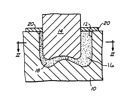
Reference to Figures 1 and 2 will illustrate one
embodiment of this invention in its simplest form utilizing
only orbital relative motion, wherein workpiece 10 could be a
die casting mold or the like having a mold cavity 12 therein to
be abraded. A displacer 14, having a profile smaller than
cavity 12, is adapted to be insertable within cavity 12 to
provide a medium chamber 16 formed between the entire surface
of cavity 12 and displacer 14. A visco-elastic abrasive medium
18 is deposited within medium chamber 16, and is sealed therein
by sealing ring 20, securely attached around displacer 14, when
displacer 14 is suitable inserted within cavity 12, as shown.
With displacer 14 and sealing ring 20 biased against the visco-
elastic abrasive medium 18, a relative orbital motion is
effected between workpiece 10 and displacer 14. This relative
orbital motion will then cause a relative translational motion
between the medium 18 and the contacting surfaces of workpiece
10 and displacer 14, thereby causing the surface of the cavity
12 to be abraded as desired. The relative orbital motion is
continued until the workpiece 10 is abraded to the extent
desired.
With reference to Figure 2, the circular arrows passing
over displacer 14 represents the orbital path of the axis
~0019'~0
PATENT
EH-0025-PCT-P
9
thereof. In this embodiment, the motion of the visco-elastic
abrasive medium 18a is caused by the relative orbital motion
between the workpiece 10 and displacer 14 which tends to push
or extrude the medium 18 around the cavity 12 as it is squeezed
from an area of the chamber of diminishing section into an area
of expanding section. In this embodiment, the relative orbital
motion can be combined with a relative rotational motion so
that in essence, with respect to the workpiece 10, the
displacer 14 revolves on its axis as it orbits within cavity
12.
In the embodiment described above, it should be apparent
that the visco-elastic abrasive medium 18 will serve to abrade
the outer surface of displacer 14 as well as the workpiece
surface of cavity 12. Accordingly, either piece could be
representative of the workpiece as well as the displacer. It
follows therefore, that Figures 1 and 2 could be representative
of an application whereby the outer and lower surfaces of a
cylindrical workpiece are abraded by utilizing a cavity
containing body as the displacer.
In a more practical application of the above described
embodiment the efficiency of the operation can be improved and
wear of the displacer surface minimized if the surface of the
displacer 14 is such that it resist flow of the visco-elastic
abrasive medium 18 therepast. This can readily be done by any
of several ways. For example, fin-like protrusions can be
incorporated on the surface of the displacer which will project
into the body of medium so that the medium is more or less
carried along with the motion of the displacer and the relative
~0~19"0
PATENT
EH-0025-PCT-P
displacement between the displacer and the medium is reduced
while enhancing the relative motion between the medium and the
workpiece. It is also known that the medium will tend to
adhere to porous or roughened surfaces as well as surfaces
5 coated with polyurethane, silicon rubber or like materials.
Accordingly, if the surface of the displacer 14 is made porous
or roughened, or is coated with polyurethane or silicon rubber,
the medium will tend to adhere thereto, so that when there is
relative movement between such a displacer and a workpiece
10 surface, the motion between the workpiece and medium is
enhanced at the expense of motion between the displacer and the
medium.
The embodiment depicted in Figure 3 is substantially like
that depicted in Figure 2 described above, except that there is
a relative lateral oscillatory motion between the displacer 12a
and the workpiece 10a, here again with or without rotational
motion. In this embodiment, the visco-elastic abrasive medium
18a is forced to flow back and forth within the chamber 16a by
the relative lateral oscillatory motion, which can be in two or
more planes as represented by the arrows imposed over the
displacer 14a.
In the two embodiments described above, it should be
apparent that the form of relative movement between the
displacer and the workpiece is not particularly critical,
particularly where the surface of the workpiece is uniform and
continuous as shown. Indeed, the orbital or reciprocal motions
as depicted in these two embodiments will have comparable
abrading effects on the workpiece.
CA 02001970 1999-07-16
- 11 -
In the embodiment shown in Figure 4 the principal of
the application is the same except that a more complex
workpiece surf<~ce is to be worked. As shown in Figure 4,
the workpiece 20 may be a gear or the like having
uniformly spaced gear-teeth 22 around the cylindrical
periphery thereof. The displacer 24 is an annular shaped
form which i,s positioned to encircle workpiece 20,
providing a chamber 26 therebetween. Displacer 24 is
preferably provided with a plurality of protrusions 25
extending inwardly, and having a size and spacing as can
be insertable between gear-teeth 22. When a visco-
elastic abrasi~se medium 28 is sealed within chamber 26, a
relative motion is imparted between workpiece 20 and
displacer 24. In this embodiment, the relative motion
between the workpiece 20 and displacer 24 is a
combination of rotational and orbital motion so that the
gear-teeth 22 will come close to meshing with protrusions
as workpiece 20 rotates and orbits, i.e. "rolls" along
the inner surf: ace of displacer 24, but leaving a small
20 gap so that the two components do not in fact come into
contact. Accordingly, when the chamber 26 is filled with
a visco-elastic abrasive medium 28, and workpiece 20 and
displacer 24 put into relative motion as described, the
medium 28 will not only be forced to revolve about
25 chamber 26 in a manner similar to that described above,
but the near meshing of gear-teeth 22 into protrusions 25
will cause the medium to flow into and out of the spaces
between the gear teeth 22 so that it will flow along the
surface of gear-teeth 22 to abrade the surface thereof as
desired. While a smooth surface on displacer 24 could be
provided, it slZOUld be readily apparent
~0019'~0
PATENT
E8-0025-PCT-P
12
that medium 28 would not be squeezed from the recesses between
gear-teeth 22, so that the abrasion would be concentrated on
the outer periphery of gear teeth 22, with little abrasion on
the inner surfaces thereof.
In the embodiment illustrated in Figure 5, a three
dimensional machining action is exemplified. Here, the
workpiece 30 has a triangular opening therethrough to be
machined. A mating but substantially smaller triangular-sided
displacer 32 is positioned within the triangular opening in
workpiece 30, having sufficiently smaller dimensions so that
there is sufficient space between the triangular opening and
the displacer 32 to form a medium chamber 34 therearound. The
workpiece 30 and/or the displacer 32 are mounted to a suitable
means (not shown) as will impart a relative triangular
translational motion between the workpiece 30 and displacer 32
as depicted by the arrow over displacer 32 so that the corners
of the displacer 32 will move into the corners of the workpiece
30. As already described, a visco-elastic abrasive medium is
deposited within the medium chamber 34 and sealed therein
before the triangular orbital motion is started. When the
motion is started, the medium is forced to flow within the
three-sided medium chamber as it is squeezed and extruded from
from between two opposing surfaces which are coming together
and into the space between two opposing surfaces that are
moving apart.
In the embodiment illustrated in Figures 7 and 8, the
principle of the abrasion action is substantially the same,
except that there is a vertical reciprocal relative motion
CA 02001970 1999-07-16
- 13 -
between the workpiece 40 and the displaces 42, such that
the visco-elastic abrasive medium is virtually squeezed
out of the media chamber 44 with each downward movement
of the displaces 42. In the embodiment as illustrated,
an elastic sleeve member 46, such as a length of heavy
rubber pipe, is secured around the upper periphery of
workpiece 40 and the lower periphery of displaces 42, and
there held by clamps 48. As shown in Figure 7, the
arrangement is set up in its starting position with the
displaces 42 i:n its fully upward position with the visco-
elastic abrasive medium disposed within the media chamber
44 such that t:he sides of media chamber are closed by the
resilient sleeve member 46. As the displaces 42
commences its downward relative motion into the cavity of
workpiece 40, the visco-elastic abrasive medium is
squeezed or extruded from the cavity or media chamber 44
moving upward between the vertical surfaces of workpiece
40 and displaces 42 thereby abrading the vertical
surfaces of workpiece 40. Since the visco-elastic
abrasive medium has no place to go as the media chamber
44 becomes progressively smaller, the pressure of the
medium forces the sides of elastic sleeve member 46 to be
stretched outward to take up the excess volume of the
visco-elastic abrasive medium, as illustrated in Figure
7. Subsequently, when the displaces 42 starts its upward
relative motion, elastic sleeve member 46 will force the
visco-elastic abrasive medium back into the expanding
media chamber, with the system eventually returning to
that as illustrated in Figure 6. This cycle is repeated
each time the displaces 42 reciprocates.
CA 02001970 1999-07-16
- 14 -
In the vertically reciprocating embodiment described
above, it should be apparent that there will be some
degree of uneven abrasive action on the workpiece 40 and
the displaces 42, since there will be progressively more
visco-elastic abrasive medium movement along the upper
vertical surfaces of the workpiece 40, and lower vertical
surfaces of th.e displaces 42, than there will be at the
opposite surfaces thereof or along the horizontal
surfaces. This result should be obvious because the
upper portion of the vertical cavity walls will be
abraded as soon as the displaces moves downward adj acent
thereto and will continue to be abraded as the displaces
continues to move downward. The lower portion of those
cavity walls, however, will not be significantly abraded
until the displaces moves adjacent thereto. Such an
uneven abrasive action can be utilized to an advantage in
some applications, such as the finishing of mold cavities
and other workpieces, where some degree of taper is
essential. This characteristic can be either minimized
or enhanced by the proper design of the displaces to
workpiece interface. As an example thereof, Figure 8
represents a displaces design as will minimize uneven
abrasion, while Figure 9 illustrates a design as utilized
to maximize uneven abrasion to the extent of radiusing
the upper corner of the cavity in the workpiece. With
reference to Figure 8, it can be seen that displaces 52
is provided with heavy collar or flange portion 54 around
the lower ext~__°emity thereof. Accordingly, as displaces
52 moves downward within workpiece 50 and extrudes the
visco-elastic abrasive medium upward along the side wall
of workpiece 50, the velocity of the medium will be
greatest in the narrowed volume adjacent to the flange
CA 02001970 1999-07-16
- 15 -
54. Behind the, flange 54, where the spacing between
workpiece 50 and displacer 52 is considerably increased,
the upward velocity of the medium is greatly reduced, and
the abrasive action on the workpiece side wall is
similarly gre<~tly reduced. In this situation, the
concentration of heavy abrasion adjacent to the flange 54
is uniform throughout the full travel length of the
flange 54.
Figure 9 illustrates a reverse situation where the
displacer 62 is designed to maximize abrasion at the
upper edge of the cavity surface in workpiece 60 to
effect a radiusing thereof. Because the entire side
surface of di;splacer 62 is angled with respect to the
side surface of the cavity within workpiece 60, the
abrasive action of the visco-elastic abrasive medium will
be concentrated at that area where its passage is most
restricted, in. this case the upper edge of the cavity.
The solid line is representative of the starting surface
of the cavit~~ side wall, while the dotted line is
representative of the form of the finished cavity side
wall.
In addition to the above discussed variations in the
design of the work;piece-displacer interface, there are
numerous other concepts that could be utilized to effect
differing abrasion requirements. Here too, differing
forms of motion in combination with vertical reciprocal
motion could be utilized to effect differing abrasion
requirements. In addition to combining an orbital, or
horizontal reciprocal motion with the vertical reciprocal
motion, the angle of the vertical reciprocal motion can
be varies so that it moves downward at an
2~19'70
PATENT
E8-0025-PCT-P
16
angle into the workpiece to be abraded, or the angle can be
slowly rotated so that displacer moves downward into the
workpiece at a constantly changing angle. Accordingly, the
variations seem almost countless, and are limited only by ones
imagination to formulate new variations of motion and displacer
design to satisfy a great variety of abrading requirements.
Typical parameter ranges for the embodiments illustrated
would include grit sizes of 6 microns to 16 mesh, gap distance
of 0.005-1.5 centimeters (0.002-0.500 inches), time treatments
of 5-60 minutes, revolutions, orbits or vibrations of 20 to
20,000, and amplitudes of vibration of 0.06-1.5 centimeters
(0.025-0.500 inches). Specifically, after substantially
filling the gap with a visco-elastic abrasive medium the
displacer of Figure 6 could be operated at 500 vibrations per
minute with an amplitude of 0.13 centimeters (0.05 inches) for
5 minutes and a gap of 0.013 centimeters (0.005 inches) would
be sufficient of a grit size of 10 microns.
It is preferable that the plastic carrier matrix have a
sufficient body at moderate pressure and low velocity to press
the abrasive particles against the work surface with sufficient
force to produce the results desired. One mixture successfully
used in the invention is MV70 Extrude-Hone media, comprising
50~ by volume of silicon carbide abrasive grit and 50~k by
volume of silicon bouncing putty (borosiloxane) carrier
(matrix) having a ratio of approximately 2:1 by weight.
By definition, silicone bouncing putty (borosiloxane)
exhibits many of the characteristics of a fluid. Under
pressure it becomes less flowable and more like a solid. It
2003.~'~0
PATENT
EH-0025-PCT-P
17
conforms exactly to the shape of whatever confines it and this
helps in abrading intricate shapes and details. It should be
noted that silicone bouncing putty (borosiloxane) is
particularly useful in the invention as it is well known that
this material becomes harder when subjected to sudden shear
force such as when squeezed in the gap between the opposed
surfaces as they are moved relative to one another. This
increased stiffness enhances abrasion of the workpiece by
holding the abrasive particles more firmly in place and
transferring the driving force of the working member to the
abrasive grains at the work surface.
A non-rheopectic abrasive medium suitable for use in some
situations is that described in U.S. Patent No. 3,819,343 -
Rhoades.
This invention may be utilized to hone or abrade machined
parts, die castings, forgings, sand castings, investment
castings and extruded shapes. It is applicable to all
materials such as steel, aluminum, brass, bronze, plastics,
glass and other compositions and materials as needed.
Obviously, the abrasive used in the carrier matrix will be
varied to suit the job. A satisfactory abrasive to use in
working on steel is boron carbide (BC) which is readily
obtained from the Norton Company in standard grit sizes.
Another abrasive which is useful for many applications is
aluminum oxide. Other abrasives might include diamond dust
silicon carbide, rouge, corrundum,garnet, aluminum, glass or,
in some unusual operations, softer material such as fiber or
shell material. Commonly, the abrasive will vary from about 2
2~9190
PATENT
EH-0025-PCT-P
18
to 4 grams of abrasive particles per gram of the matrix
material.
The above-mentioned visco-elastic honing media act as a
surface abrading tool and are unique for the reason that the
abrasive grit is held or contained in a random repositioning
arrangement in a plastic matrix. The grain particles in use in
the process of this invention are sharp until the sum of all
points or edges have been exposed many times, as opposed to the
traditional concept of an abrasive "stone" or lap wherein the
grain particle is fixed and presents one cutting point or edge
which is maintained until dulling causes removal by means of a
dressing operation.
The fastest cutting action, which is also consistent with
the most uniform results, occurs when the medium exhibits an
oily nonadhering contact with the work surface. It would
appear that when in this condition the medium has the greatest
opportunity to pass through the gap at a constant cross
sectional pace. This is contrary to a fluid flow which is
greatest through the center and supposedly "zero" along the
wall.
It should be apparent from the above described embodiments
of this invention that there are many possible variations that
could be utilized to effect many differing abrading
requirements. Accordingly, the present invention is not
limited to the preferred embodiments disclosed herein, and that
many modifications in construction, arrangement, use and
operation are possible within the true spirit of the invention.
Accordingly, the present invention is to be considered as
~oo~~~o
PATENT
EH-0025-PCT-P
19
including all such modifications and variations coming within
the scope of the appended claims.