Note: Descriptions are shown in the official language in which they were submitted.
- ~ --
2no2no7
INJECTION MOLDING APPARATUS AND METHOD
BACKGROUND OF INVENTION
1. Field of Invention
The present invention relates to apparatus and methods
for making injection molded thermoplastic parts, particularly
gas assisted injection molding of parts having a smooth outer
skin and a hollow core.
2. Prior Art
Various injection molding techniques have heretofore
been proposed to use less material and achieve weight and cost
reduction while maintaining structural properties and providing
a smooth outer surface or skin that does not require sanding
or other finishing. Blowing agents, including gas, can be used
to provide a porous, foamed or cellular core and in some cases
a hollow core. When gas is used to form a hollow core, the gas
can be injected into the plastic melt stream at the nozzle or
directly into the mold, preferably in a controlled manner to
achieve the desired core structure.
United States Hendry Patent No. 4,474,717 discloses
several apparatus and methods wherein gas is injected into the
mold by means of a gas injection probe. A small amount of
plastic is first injected into the mold to encapsulate a gas
injection probe and thereafter gas is injected through the
probe while injection of the plastic continues to form the
desired core structure. At the end of the molding operation
gas pressure in the mold is relieved by exhausting the mold
cavity through the probe which acts as a decompression valve.
A similar gas injection - decompression valve in the mold is
also disclosed in United States Sayer Patent No. 4,740,150. In
both the Hendry and Sayer paten'ts the gas injection probe or
nozzle is shown mounted in that half of the mold opposite the
200~7
mold half through which the plastic is injected, as from a
reciprocating screw injection molding machine. Although
injecting and/or exhausting gas into the mold cavity in the
manner taught by the Hendry and Sayer patents may well provide
thedesiredcore structure, modification of each mold is required
to accommodate the gas injection nozzle or probe. This may be
expensive and involves care in selecting the location of the
gas injection nozzle, particularly in multiple cavity molds and
in retrofitting existing molds.
Othergas injection techniques have also beenproposed
wherein the gas or a foaming agent is introduced into the melt
stream prior to the mold cavity e at the nozzle of the plastic
injectorasshownin United States Friedrich Patent No. 4,101,617
or into the cavity after plastic injection by a special manifold
as shown United States Olabisi Patent No. 4,136,220. Again,
modification of the nozzle or manifold may also be expensive
and require changing the nozzle or manifold for different
applications depending on the part being molded by that machine.
Other gas injection locations have also been
suggested. U. S. Patent No. 4,498,860 (Gahan) discloses an
inclined retractable piston mounted in a mold half that can
be extended to close off a reverse taper sprue passageway and
thereby cut off the sprue. A small pipe coaxial with the piston
is disclosed for injecting gas into the plastic material to
flow with the plastic through the mold space. Here again rather
elaborate modification of the mold is required to accommodate
the holderforthe spruecut-off piston. Theinclined orientation
of the gas injection tube would undoubtedly cause uneven
distribution of the gas in the plastic entering the mold and
otherwise detract from effective gas injection.
Whether gas is injected into the mold as in the Sayer
. r
-
2002007
and Hendry patents or into the melt stream before the mold as
in the Friedrich patent, the gas injection should be compatible
with different gas injection systems to precisely control
injection of the gas. This may require further modification
of the nozzle or the mold which in turn adds to expense,
particularlv ~here the gas injection system is installed as a
retrofit for an existing mold to make a previously solid part
into a hollow core part.
In retrofitting existing injection molding equipment
and molds, as well as with new equipment, various techniques
have been proposed to more precisely control the gas injection
and achieve the desired core structure repeatably over long
production runs. One approach is described in general terms
in the aforementioned United States Sayer Patent No. 4,740,150
and in British Patent Specification No. 2,139,548 referred to
therein, wherein a preselected or measured volume of pressurized
gas is injected into the mold during each molding cycle.
A process u~ing what may be generally termed as preset
pressure has also been proposed in Baxi European application,
Application No. 87304002.6, filed May 5, 1987, published December
12, 1987, Publication No. 0250080A2, Bulletin 87/52. With this
process, as contrasted to the preset volume technique, the
quantity of gas that is introduced into the mold is not directly
measured but only the pressure of the gas is controlled. A gas
supply source is provided along with gas pressurization means
for pressurizing the gas to a preset pressure which is at least
as great as the pressure at which the molten plastic material
is introduced into the mold. A storage chamber is provided for
storing gas at the preset pressure so that the gas is immediately
available for use when injection of the plastic material is
initiated. Gas pressure maintains the plastic against the
~ - 2002007
surfaces of the mold cavity as the plastic cools and until the
plastic can sustain the form dictated by the mold to provide
an essentially hollow part. As set forth in European Patent
Publication 0,250,080, prior to injection of the plastic, a
high pressure gas storage tank is fully charged at the pressure
preset for that molding operation. Just after plastic injection
is initiated.'.igh pressure gas from the storage tank is injected
into the plastic melt steam by a feed chamber in the nozzle.
The high pressure tank is charged and recharged by a pump
controlled by a pressure switch so that sufficient gas in the
high pressure tank is always available at the preset pressure.
Asahi Dow Ltd. Japanese Application No. 120318/1973, filed
October 25, 1973, published March 27, 1982, Publication No.
14968/1982, shows a similar arrangement for injecting gas via
a high pressure piston or ram and injection inlet at the nozzle.
Although the preset volume and preset pressure
processes described in the prior art may well provide improved
results as contrasted to gas injection that is not as precisely
controlled, both processes have disadvantages that detract from
precise and repeatable control of the gas injection. In the
constant volume process it isdifficult to maintain repeatability
over many molding cycles due to variations inherent with constant
volume cylinder and piston arrangements caused by wear and other
variations with time and extended use. In the preset pressure
method using a high pressure storage tank that must be
replenished, the preset pressure can and will vary during an
injection cycle as gas is released from the tank and replenished
by the pump.
Accordingly it is desirable to provide improved
methods and apparatus for injection molding of hollow parts
which overcome the foregoing and other difficulties while
providing better and more advantageous overall results.
20~2~
BRIEF SUMMARY OF THE INVENTION
; In accordance with the present invention new and
improved methods and apparatus are provided for producing a
hollow injection molded part.
More particularly, in accordance with one important
aspect of the present invention there is provided a method and
apparatus for making a plastic injection molded part with a
smooth surfa-e or skin wherein thermoplastic material is injected
as a molten stream into the mold cavity through a sprue bushing
fixed in the mold. Simultaneously, an unmeasured quantity of
inert gas is introduced through an adapter into the molten
stream at the sprue bushing substantially coaxially with the
melt stream and at a pressure sufficient to penetrate the
thermoplastic material to form a gas cavity in the molten
material in the mold. For retrofitting an existing mold, an
adapter can be added to the existing sprue bushing. For new
molds the sprue bushing is modified at the nozzel end.
In accordance with another aspect of the present
invention, during plastic injection the gas is maintained at a
high pressure, preset, constant and adequate to maintain the
plastic against the mold surface until it is self-supporting.
The gas is exhausted from the mold, back through the sprue
bushing and adapter, before the mold is opened. Adequate preset
high pressure is maintained at the gas supply by a large cylinder
having a positive displacement member therein that is controlled
----- by a pressure sensor in the gas pressure line to the mold to
maintain preset adequate gas pressure within the cavity during
injection and cooling.
The principal object of the present invention is to
overcome, or at least minimize, the disadvantages of prior art
gas assisted injection molding and provide methods and apparatus
for gas assisted injection molding that produce a superior
plastic part having a hollow cavity therein and a smooth outer
~ :
z~ 7 ~
,-
;~
surface and reduced sink marks and part warp and which are
effective, efficient and economical and provide greater -
flexibility using conventional injection molding equipment.
:~ .
BRIEF DESCRIPTION OF THE DRAWINGS
The above objects and other features and advantages
of the present invention will be apparent from the following
detailed description, appended claims and accompanying drawings
in which:
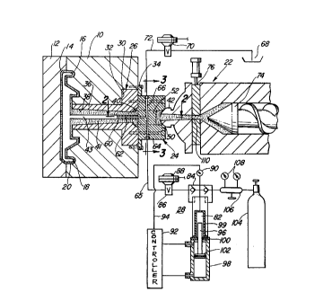
FIG. 1 is a fragmentary elevational plan view, partly
in cross section, schematically illustrating a mold with a sprue
bushing,a spruebushing adaptor,a reciprocating screwinjection
molding machine and a pressurized gas supply system;
FIG. 2 is an enlarged fragmentary sectional view taken
on lines 2-2 of FIG. l;
FIG. 3 is an enlarged fragmentary sectional view taken
on lines 3-3 of FIG. l; and
FIG. 4 schematically illustrates a further embodiment
of the present invention applied to a mold having four openings
in the mold cavity.
It will be understood that the drawings described
above merely illustrate a preferred embodiment of the present
invention and that other embodiments are contemplated within
the scope of the claims hereinafter set forth.
DETAILED DESCRIPTION OF THE DRAWINGS
Referring generally to the molding apparatus shown
in FIG. 1, a stationary mold half 10 and a moveable mold half 12
are shown in their closed position defining a mold cavity 14
for molding a plastic part 16 having an outer shell 18 a hollow
::
zoo~oo~ ~
core 20. Plastic is injected into cavity 14 through a sprue
bushing adapter 24, and a sprue bushing 26. Gas from a supply
system designated generally at 28 is introduced into the melt
stream at sprue passage 38 via adapter 24. In the embodiment
being described adapter 24 has been retrofitted to an existing
mold already having a conventional sprue bushing 26. Existing
molds are retrofitted when it is desired to convert molding of
a solid part to molding the same part with a hollow core such
as core 20.
Referring to FIGS. 1-3 in greater detail bushing 26
has a flanged head 30 mounted in a recess 32 in mold half 10 by
a press fit and by a retaining plate 34 bolted on mold half 10.
A bushing sleeve 36 integral with head 30 extends through mold
half 10 and has an outwardly tapered sprue passage 38 opening
into cavity 14 at the left end as viewed in FIG. 1. Sleeve 36
may also be press fitted in mold half 10. Sprue passage 38 opens
at its narrow end in head 30 at a hemispherical recess 40 that
provided a seat for a nozzel 42 of injection molding machine
22 prior to retrofit. At the completion of an injection, passage
36 contains a sprue in the area generally designated at 41 and
the sprue will have a gas channel 43 therethrough.
As is generally well known sprue bushings such as
bushing 26 provide inexpensive protection of the mold so that
damage occurs at the bushing which can be replaced inexpensively.
To this end, sprue bushing 26 typically is made of hardened
steel to withstand the impact of the nozzle, both during setup
and repeated injection cycling as the injection forces are
applied at the interface between bushing 26 and nozzle 42.
Sprue passage 38 conventionally has a ground and
highly polished finish to minimize friction with the melt and
thereby minimize frictional heating of the plastic that would
:
-7-
2~0;~ )7
cause degradation and burn spots in the finished product.
Repeated injection through the sprue passage 38 will, over
extended use, scratch and scorch the surface due to the
abrasiveness of the plastic material. This wear and surface
imperfection may be pronounced with glass filled plastic, for
example. A worn sprue passage, particularly at high injection
speeds, also causes turbulance and frictional flow at the walls,
creating undesirable pressure drops, interfering with proper
filling of the mold and impairing the flow of the plastic to
the mold extremities. In any event, conventional sprue bushings
provide an inexpensive way to repair the damage by replacing
the bushing. Although bushing 36 is illustrated as unheated,
it should be understood that the present invention is equally
applicable to heated sprue applications.
Sprue bushing adapter 24 compreses a steel body 50
having an integral torpedo like web 52 transverse of a through
passage 54 in body 50 splitting passage 54 into two aperatures
56 at the torpedo web. Body 50 is also hardened steel and has
a nozzle seat 51 and at the inlet end of passsage 54. Body 50
is bolted on bushing 26 at 58 and may also be silver soldered at
the interface with head 30 and recess 40 to eliminate flash.
Web 50 has an integral needle-like gas injection probe or nozzle
60 extending coaxially within sprue passage 38 and having a gas
passage 62 therein. ~dapter 24 has opposed radial gas inlet
and exhaust passages 64, 66 that extend through web 52 and
communicate at their inner ends at a T connection with passage
62 in nozzle probe 60. Inlet passage 64 is connected at its
.,. . ~ .
outer end to gas supply system 28 via a high pressure line 65. ;~
Exhaust passage 66 is connected to a decompression baffle 68 via ;-~
a solenoid operated valve 70 and line 72. Preferably exhaust ~'~
passage 66 has a larger diameter, than passage 64, say twice
~ )20~)7 i- ~
-
as large, so as not to get plugged if plastic is sucked back
when cavity 14 isdecompressed. Although probe 60 is illustrated
projecting slightly into sprue passage 38, it can be longer or
shorter, depending on the specific application. In one
application the probe opened generally in line with the juncture
of recess 32 and sprue passage 38 and in another application
extended nearly to cavity 14. In both cases, however, the
passage 62 was coaxial with the sprue bushing to inject gas
coaxially into the melt stream in the direction material flow.
Inject on molding machine 22 has a conventional
reciprocating screw 74 and cylinder operated shut-off valve 76.
In FIG. 1, screw 74 is shown at the end of its stroke just prior
to closing of the valve 76 with part 16 substantially fully
formed.
Pressurized gas is provided to sprue bushing adapter
24 during the injection stroke via a line 75 from a high pressure
chamber 82 through a check valve assembly 84 and a valve 86
operated by solenoid 88. The gas pressure in chamber 82 is
monitored by a gas pressure indicator-sensor 90 that provides
an electrical output signal to controller 92 via lead 94 when
the gas pressure falls below a present pressure. When gas in
chamber 82 is delivered to pressure line 75 through check valve
assembly 34 and valve 86, piston rod 96 is moved by an hydraulic
cylinder 98 which in turn is operated by controller 92 to
decrease the volume of chamber and maintain constant pressure.
Rod 96 projects into chamber 82 but has no sliding seals on the
chamber walls 99. Rather rod 82 extends downwardly through the
walls of cylinder 98 and chamber 82 and wet metallic seals 100 to
a piston 102 in cylinder 98. Low pressure gas is supplied to
chamber 82 from a supply tank 104 via reducing valve 106 and
check valves 84. The gas is preferably nitrogen.
~ :
~OC~Z007
.
Prior to the start of the molding cycle, valves 70
and 86 are closed and inert gas is stored in chamber 82 by
activating controller 92 and hydraulic cylinder 98 to retract
rod 96 and piston 102 down as viewed in FIG.l. This draws
relatively low pressure gas from tank 104, into the empty gas
chamber 82. The gas will continue to flow into chamber 82 until
the pressure in the chamber equals the pressure of the gas
entering from the supply tank 104, which is set by pressure
reducing valve 100 and indicated by pressure gages 108. The
gas pressure in chamber 82 may be relatively low at say 150 to
250 psi. Check valve assembly 84 prevents gas from returning
to tank 104. Cylinder 98 is then actuated to extend rod 96
into chamber 82, compressing the gas in chamber 82 to a desired
preset high pressure, for example 2000 psi and higher, as set
and indicated at pressure indicator-sensor 90. In general, the
gas pressure is set to be at least greater than the plastic
injection pressure at sprue bushing 26 and cavity 14. At the
desired pressure required, the piston 102 will stop in response
to the control signal at lead 94 and stay in the up position
until such time, during the subsequent injection operation when
the pressure drops below the required preset gas pressure. With
chamber 82 fully charged to the desired present pressure, and
the valves 70, 84, 86 closed, the molding cycle is in the start
position.
To initiate the molding cycle, the molding press
clamping unit (now shown) is closed, holding mold halfs 10 and
12 closed under a clamping force which is in excess of the
plastic melt and gas injection pressures Under the control
of the injection cycle controller (not shown) for machine 22,
nozzle shut-off valve 76 is opened and screw 74 is activated to
ram molten plastic 110 through nozzle 42, adapter 24, sprue
; :
X~ 32007 ~: -
bushing 26 a~d into the mold cavity 14. As the molten plastic
enters the sprue bushing 26 past the gas injection probe 60,
valve 86 is immediately opened by the cycle controller, allowing
high pressure gas from chamber 82 to flow through line 65, into
passages 64 and 62 where it is in~ected into the melt stream in
the sprue passage 38. Preferably gas injection is initiated
so that the outlet end of nozzle probe 50 is encapsulated with
molten plastic just before the gas flow starts in a manner
similar to that disclosed in the above identified U.S. Hendry
Patent No. 4,474,717. During plastic injection exhaust valve
70 remains closed.
As t:.e gas enters the melt stream in the sprue passage
38, the higher gas pressure pushes the molten plastic rapidly
to mold cavity 14 and against the cavity walls forming the
hollow core 20 as the plastic cools. The pressure of the gas
entering the melt stream during plastic injection and maintained ~;
in cavity 20 via gas channel 43 during cooling is constant and
does not vary significantly during the molding cycle. When the
gas pressure in chamber82 starts todrop, the pressure indicator-
sensor 90, actuates controller 92 which moves piston 102 upward
to extend rod 96 further into chamber 82 to maintain gas
pressure at the preselected level in chamber 82 and core 20.
When screw 74 finishes its forward movement the gas
flow will continue for a short period to pack molten plastic ~-
against the mold surfaces. Valve 86 is then closed by the cycle
controller. For a period of time set by the controller cycle
(not shown), this gas pressure is held constant until the molten
plastic shell 16 in the mold cavity 14 has cooled sufficiently
to be self-supporting. The gas exhaust val~e 70 is then opened
by the cycle controller to decompressjgas from cavity 14, back
through the open gas channel 43 in sprue 41, passages 54, 66,
Z~)~Z6~07
.
line 72 and vent the exhausted gas to the ambient atmosphere
via baffle 68. The mold can subsequently be opened and the
molded part 16 removed from the mold.
During the decompression time at cavity 11 and between
molding cycles, cylinder 98 retracts piston 102 and rod 98.
Chamber 82 is recharged and then rod 96 is extended until the
gas pressure in chamber 82 reaches the desired setting at
indicator on the sensor 90. The system is then ready for a
repeat cycle, with valves 86 and 70 closed.
With the arrangement described, the gas injection
probe 60 opens in the sprue bushing 36 coaxial with sprue passage
38 in the same d;rection as the flow of the melt stream. This
allows the use of a standard sprue bushing opening at the mold
without altering the standard sprue bushing or opening design.
This is particularly important in a retrofit since the sprue
bushing configuration need not change including where the sprue
passage 38 opens into the cavity. Hence, variation in plastic
flow parameters are not introduced from standard sprue design.
Anotheradvantage ofgas injection at the sprue bushing
is the~elimination of a cold slug that would be present if the
gas is injected and exhausted at the nozzle. When gas is
exhausted through the nozzle it cools the nozzle tip slightly
causing freeze up and cold slugs.
Considering further advantages of coaxial gas
injection of the sprue bushing in the direction of material
flow, after the gas inlet has been encapsulated by the melt
stream, as the plastic and gas injection continue, an envelope
is formed which moves into the mold cavity 14 and expands into
the cavity extremities, all while the envelope is sufficiently
fluid to expand under the gas pressure. Once the envelope fills
0~)7
the cavity to form shell 18, particularly with constant pressure
maintained inside the shell, the shell is packed against the
wall until such time as it is self supporting. Coaxial injection
of the gas illtO the melt stream at the sprue bushing provides
uniform distribution of the gas and gas pressure forces in the
melt stream and the envelope as it expands in the mold cavity.
Coaxial gas injection at the sprue bushing also insures that
the gas enters the melt stream where it is always vicose.
Coaxial injection of the gas at the sprue bushing in the direction
of flow of the melt stream also minimizes turbulance in the
melt stream which could result in isolated bubbles in the final
part.
Although gas injection at the sprue bushing has been
described in the preferred embodiment in connection with the
constant pressure gas delivery system 28, the advantages are
useful with other gas delivery systems, for example of the types
disclosed in the above identified prior art.
Similarly, although gas injection at the sprue bushing
has been described for retrofitting an existing mold it is
equally advantageous with new molds. For new mold applications,
inexpensive standard sprue bushings can be used and the adapter
24 fastened to the sprue bushing and preferably silver soldered
at interfaces to prevent flash. Where special sprue bushings
are required part of the adapter can be manufactured as an
integral part of the bushing. However, for retrofitting existing
molds or for new mold applications the gas injection mechanism
is part of the sprue bushing as contrasted to being in the
nozzle or directly in the mold. Hence, no significlant
modification of either the mold or the injection molding machine
is required. If the sprue bushing or the adapter gets worn or
damaged, it can simply be removed and replaced.
-13-
2~ Q7
Although the sprue bushing is preferred for many
applications, it will be understood that for some applications
the mold does not need to have a sprue bushing. The adapter 24
to provide gas injection would then be mounted on the mold to
convey the melt stream to the cavity so that the gas and melt --~
,., .. ~ .. , . - .
stream enter the mold cavity together. In such applications
the part would have some portion, in the nature of a sprue,
where the plastic is injected and which is either nonfunctional,
part of the runner system or some other portion that is later
removed from the finished parts. Hence in the broader sense,
the present invention contemplates use of the adapter to inject
gas into the melt stream downstream and independent of the
nozzle at a sprue or sprue like portion of the part or part
runners.
FIG. 4 shows a further embodiment of the present
invention where the mold cavity (not shown) has four hot sprues
120 commonly known as hot drops. Each hot drop sprue 120 is
connected by hot runners 122, 123 to a main sprue bushing 124
that would normally receive plastic from the nozzle of the
injection molding machine. By mounting an adapter like adapter
24 at bushing 124, gas can be introduced into the melt stream
for distribution to each of the four hot drop sprues 120. To
even further insure even gas distribution to each of the hot
drop sprues, the gas injection probe can be fashioned to branch
into and extend through runners 123, 122 to each of the hot
drop sprues 120 as indicated by tubes 126 shown in dotted lines
in FIG. 4. The tubes 126 open in the melt stream at each hot
drop sprue 120 coaxially therewith and in the direction of
material flow into the mold.
The gas delivery system 28!also has advantages over
the prior art delivery systems ide~ntified-above. Gas delivery
)~ .
Z~Z007
system 28 maintains constant pressure during injection and
cooling in the mold to insure that the part is packed in full
contact with the cavity wall until the part is self supporting.
Constant pressure is achieved because as soon as any gas is
depleted from ch~mber 82, rod 96 is extended, instantaneously
and automatically, into the chamber 28 displacing the depleted
gas and maintaining the pressure constant. This is in contrast
to constant volume systems where the gas pressure drops off
during injection and prior art attempts to achieve substantially
constant pressure by pistons, pumps and the like.
Chamber 82, rod 96 and the stroke of piston 102 are
selected so that chamber 82 contains more than enough gas for
each injection and rod 96 never bottoms out on the chamber
walls. Consequently, once chamber 82 is pressurized to the
desired preset pressure, the pressure can be maintained constant
throughout injection by displacing the gas as it is used. This
is also in contrast to ~sing a piston in a gas compression
cylinder because more than sufficient pressurized gas for each
injection is stored in chamber 82. Rod 96 does not require
piston rings or other dry sliding seals in chamber 82.
Introduction of lubricants into the gas would impair the surface
finish or create unwanted surface and other bubbles in the part.
Although seal 100 is wetted by hydraulic fluid in cylinder 98,
the design of such metal seals to prevent hydraulic fluid from
leaking into chamber 82 is well known. Since no additional heat
is generated in chamber 82 by friction of moving seals, longer
life and more reliable operation is achieved.
As indicated earlier, gas delivery system 28 i8 a
high pressure system. Although the preset pressure will vary
depending on the molding parameters for each application,
generally gas pressures in the range of 2,000 to 7,000 psi and
. . ..
2~
even higher are contemplated, the qas injection pressure is
selected to be above the melt pressure where thegas is injected.
Typically, general purpose polymers such as polyproplyene and
polyethylene are at the lower end of the range, say 1,800 psi
in the sprue bushing 26 where the gas would be injected at a
slightly higher pressure in excess of 2,000 psi. With glass
and mica filled nylon, ABS, and Lexan, for example, at the upper
end of the range higher melt pressures of 3,500 to 7,000 psi
might be present and the gas pressure preset at indicator-sensor
90 would again be above the melt pressure.
Although gas injection at sprue bushing 26 can be
used with various gas delivery systems and gas delivery system
28 can be used to inject gas at locations other than the sprue
bushing, the combination of gas injection at the sprue bushing
using the constant gas pressure of gas delivery system 28 is
preferred. The two features are particularly compatible to
achieve a better molded part. The melt stream is still highly
viscose at the sprue bushing and at pressures that allow gas
injected at constant pressures to achieve effective coring of
the molded partand smoothsurfaces thatdo notrequirefinishing.
It will be understood that the injection molding
apparatusand method havebeendescribed hereinaboveforpurposes
of illustration and are not intended to indicate limits and
modifications of the present invention, the scope of which is
defined by the following claims.
-16