Language selection

Search

Patent 2002569 Summary

Third-party information liability

Some of the information on this Web page has been provided by external sources. The Government of Canada is not responsible for the accuracy, reliability or currency of the information supplied by external sources. Users wishing to rely upon this information should consult directly with the source of the information. Content provided by external sources is not subject to official languages, privacy and accessibility requirements.

Claims and Abstract availability

Any discrepancies in the text and image of the Claims and Abstract are due to differing posting times. Text of the Claims and Abstract are posted:

  • At the time the application is open to public inspection;
  • At the time of issue of the patent (grant).
(12) Patent Application: (11) CA 2002569
(54) English Title: DEVICE FOR INSPECTING THE INNER WALL OF A BODY
(54) French Title: DISPOSITIF D'INSPECTION DE LA PAROI INTERNE D'UN CORPS
Status: Deemed Abandoned and Beyond the Period of Reinstatement - Pending Response to Notice of Disregarded Communication
Bibliographic Data
(51) International Patent Classification (IPC):
  • G08B 21/00 (2006.01)
  • G01N 21/954 (2006.01)
(72) Inventors :
  • OBDEIJN, MARCELLINES J. J.
(73) Owners :
  • HEUFT-QUALIPLUS B.V.
(71) Applicants :
  • HEUFT-QUALIPLUS B.V.
(74) Agent: SMART & BIGGAR LP
(74) Associate agent:
(45) Issued:
(22) Filed Date: 1989-11-09
(41) Open to Public Inspection: 1990-05-28
Availability of licence: N/A
Dedicated to the Public: N/A
(25) Language of filing: English

Patent Cooperation Treaty (PCT): No

(30) Application Priority Data:
Application No. Country/Territory Date
8802933 (Netherlands (Kingdom of the)) 1988-11-28

Abstracts

English Abstract


ABSTRACT
The invention relates to the inspection of the
inside of a body, for example the inner surface of a metal
container such as a preserves can.
The best possible inspection is ensured with light-
ing from the same direction as that from which the inspection,
for example with a video camera, takes place. The invention
therefore provides a device for inspecting the inner surface
of a hollow body such as a metal container with a cylindrical
standing wall and a bottom, which device comprises:
positioning means for placing the body at a chosen
position;
a light source which is placed relative to the
positioning means such that it can light the said inner sur-
face at least approximately uniformly; and
an inspection means, for example a video camera,
which is placed relative to the positioning means such that
it can inspect the said inner surface,
whereby the direction of lighting and the direction
of inspection of each portion of the said inner surface at
least approximately coincide.


Claims

Note: Claims are shown in the official language in which they were submitted.

CLAIMS
1. Device for inspecting the inner surface of a
hollow body such as a metal container with a cylindrical
standing wall and a bottom, which device comprises:
positioning means for placing said body at a chosen
position;
a light source placed relative to said positioning
means such that it can light the said inner surface at least
approximately uniformly; and
an inspection means for example a video camera,
placed relative to said positioning means such that it can
inspect the said inner surface,
whereby the direction of lighting and the direction
of inspection of each portion of the said inner surface at
least approximately coincide.
2. Device as claimed in claim 1, characterized in
that the light source is at least approximately annular and
is disposed around the inspection means.
3. Device as claimed in claim 1, characterized by
a semi-transparent mirror disposed such that the (virtual)
images from the light source and the inspection means substan-
tially coincide.
4. Device as claimed in any of the foregoing claims,
characterized by a mirror formed, for example in frusto-coni-
cal form, such that the inspection means can inspect the
inner surface of the body with enlarged angle of aperture.
5. Device as claimed in claim 4, characterized in
that the mirror has dimensions such that via the mirror only
lighting and inspection of the standing wall of the inner
surface can take place and that lighting and inspection of
the bottom of the inner surface is directly performed.
6. Device as claimed in any of the claims 1-3,
characterized by at least three inspection means, each with
a light source added thereto, which inspection means together
can observe the total inner surface for inspection.

Description

Note: Descriptions are shown in the official language in which they were submitted.


2002569
X Sch/gn/5 Heuft
DEVICE F~R INSPRCTING THE INNER WALL OF A BODY
The invention relates to the inspection of the
inside of a body, for example the inner surface of a metal
container such as a preserves can.
For the inspection of the bottom of such a can a
video camera can ~e placed above the can for inspection and
the interior of the can may be lighted more or less diffusely
by means of a continuously or stroboscopically operating
light source.
For the standing inner wall of a preserves can such
a method of inspection is sometimes less suitable. ~he purpose
of the invention is to cause the inspection to be performed
such that de~ection of faults can take place with the greatest
possible reliability and with simple means.
The best possible inspection is ensured with light-
ing from the same direction as that from which the inspection,
for example with a video camera, takes place. The invention
therefore provides a device for inspecting the inner surface
of a hollow body such as a metal container with a cylindrical
standing wall and a bottom, which device comprises:
positioning means for placing the body at a chosen
position;
a light source which is placed relative to the
positioning means such that it can light the said inner sur-
face at least approximately uniformly; and
an inspection means, for example a video camera,
which is placed relative to the positioning means such that
it can inspect the said inner surface,
whereby the direction of lighting and the direction
of inspection of each portion of the said inner surface at
least approximately coincide.
~ he device can for example display the feature
that the light source is at any rate approximately annular
and is disposed around the inspection means. Use can be made
- : . ,., , . ~ .- . -,
. .- -. : . : ,; -:: . .
,, , - :~
: ' ' ' ' ' ~ ~ '

Z0~32569
of a number of light-emitting diodes which are disposed around
the objective lens of a video camera or also of a single
light source which is connected by means of light conductors
to a crown disposed around the said lens and in which the
light conductors end. An annular light source is hereby ob-
tained. Vse can also be made of a semi-transparent mirror
arranged such that the (virtual) images of the light source
and the inspection means substantially coincide.
In order to be able to inspect the standing inner
surface of, for example, a cylindrical container with the
greatest possible resolving power and thereby with the great-
est possible detection accuracy, use can be made of a mirror
formed, for example in frusto-conical form, such that the
inspection means can inspect the inner surface of the body
with enlarged angle of aperture. In a particular embodiment
the device displays the feature that th0 mirror has dimensions
such that via the mirror only lighting and inspection of the
standing wall of the inner surface can take place and that
lighting and inspection of the bottom of the inner surface is
directly performed.
Attention is drawn to the fact that, depending on
the form of a body for inspection and the eventual requirement
of a user to be able to inspect a determined portion of the
inner surface with greater detection accuracy, use can be
made of a mirror with adapted curvature.
A particular embodiment of the invention can be
characterized by at least three inspection means each with a
light source added thereto, which inspection means together
can observe the total inner surface for inspection. The said
at least three light sources can be embodied as a single
light source which, whether by means of light conductors or
with mirrors, causes the lighting of each portion of the
inner surface to take place from substantially the same direc-
tion as that in which the optical axis extends of each inspec-
tion means, in particular video camera.
: ., . :. - ~. -
,: ~ .,:
;' ' , ' ' ~ :

20~2S69
The invention will now be elucidated with reference
to several embodiments. In the drawing:
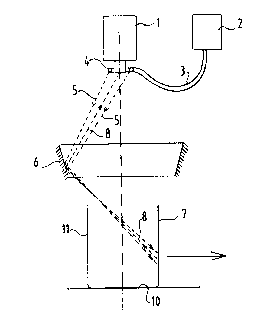
figure 1 shows a schematically represented first
embodiment;
figure 2 shows a schematic video image obtained
with the disposition according to figure 1:
figure 3 shows another embodiment;
figure 4 is yet another embodiment in schematic
vertical view; and
figure 5 is a schematic top view of the disposition
according to figure 4.
Figure 1 shows a video camera 1 and a light source
2 which gives off light by means of an optical conductor 3
via an end crown 4 of the light conductors. The light 5 coming
from these light conductors 4 is radiated into a container 7
via a conical mirror 6. The light 8 coming from the lighted
zone can be observed from approximately the same direction by
the video camera 1. The drawn rays 5, 8 indicate one lighting
and inspection zone only by way of example.
Figure 2 shows a video image 9. The video camera 1
"sees" the bottom of the can directly, as well as the standing
inner wall 11. The video camera 1 further inspects the inner
wall 11 via the conical mirror 6. This image zone is desig-
nated in figure 2 by 11'. It wil] be apparent that the use of
the conical mirror 6 achieves as it were an optical enlarge-
ment of the standing wall whereby the resolving power of the
optical system is better utilized. This is to the benefit of
the detection sensitivity.
By making use of a curved mirror instead of the
conical mirror 6 a still further effective enlargement can be
achieved.
Figure 3 shows a disposition wherein a light source
12 lights the inner surface 11 of the can 7 via a semi-trans-
parent mirror 13. The light source 12 is placed in relation
to the video camera 1 and the semi-transparent mirror 13 such
that the optical centre point of the lens system of the ca~era
1 coincides with the effective location of the light source
.. ` . ' . .: : "
;. ' ' ' :, '
,`~: , . . '-
~: ' ` , . ` , ' . '` ' ' , , ' ` . ' ' ' ` ` ':
.' :, ' ' ` . ' . ''' , .
' :`' '' ~ ' ' ' . , :
:: `' ` : .~, ,
. .

2002569
of the lamp 12.
Figure 4 shows an arrangement wherein a stroboscopic
lamp 14 lights the inside 11 of the can 7 via a three-sided
pyramid 15 via a concave mirror 16. The video camera 1 is
disposed relative to the mirror 16 such that here too the
lighting direction and the inspecting direction of the video
camera at least approximately coincide.
Figure 5 shows a top view from which can be seen
that three video cameras 1, 1' and 1'' are present, whereby
the total inner surface 11 of the can 7 can be inspected at
once. It is apparent that the embodiments according to figures
1 and 3 can inspect the entire inner surface with only one
video camera, while the arrangement according to figures 4
and 5 needs three cameras therefor. It is however noted that
the resolving power of the arrangement according to figures 4
and 5 can be correspondingly greater. The one or the other
arrangement may be preferred, depending on the desired sen-
sitivity of detection.
It is generally noted that the form of the mirrors
used can be chosen with a view to the desired result.
The use of the semi-transparent mirror according to
figure 3 can have the drawback that the quantity of light
available is effectively reduced. As compensation use could
be made for example of a stronger light source.
*****
: .- -,, , ~ . . . .
'.' ' ' - , ~, '
: ., . , :
, ., : .
: . . .~ . . .
, -

Representative Drawing
A single figure which represents the drawing illustrating the invention.
Administrative Status

2024-08-01:As part of the Next Generation Patents (NGP) transition, the Canadian Patents Database (CPD) now contains a more detailed Event History, which replicates the Event Log of our new back-office solution.

Please note that "Inactive:" events refers to events no longer in use in our new back-office solution.

For a clearer understanding of the status of the application/patent presented on this page, the site Disclaimer , as well as the definitions for Patent , Event History , Maintenance Fee  and Payment History  should be consulted.

Event History

Description Date
Inactive: IPC from MCD 2006-03-11
Inactive: Abandon-RFE+Late fee unpaid-Correspondence sent 1996-11-11
Inactive: Adhoc Request Documented 1996-11-11
Application Not Reinstated by Deadline 1993-05-09
Time Limit for Reversal Expired 1993-05-09
Inactive: Adhoc Request Documented 1992-11-09
Deemed Abandoned - Failure to Respond to Maintenance Fee Notice 1992-11-09
Application Published (Open to Public Inspection) 1990-05-28

Abandonment History

Abandonment Date Reason Reinstatement Date
1992-11-09
Owners on Record

Note: Records showing the ownership history in alphabetical order.

Current Owners on Record
HEUFT-QUALIPLUS B.V.
Past Owners on Record
MARCELLINES J. J. OBDEIJN
Past Owners that do not appear in the "Owners on Record" listing will appear in other documentation within the application.
Documents

To view selected files, please enter reCAPTCHA code :


To view images, click a link in the Document Description column. To download the documents, select one or more checkboxes in the first column and then click the "Download Selected in PDF format (Zip Archive)" or the "Download Selected as Single PDF" button.

List of published and non-published patent-specific documents on the CPD .

If you have any difficulty accessing content, you can call the Client Service Centre at 1-866-997-1936 or send them an e-mail at CIPO Client Service Centre.


Document
Description 
Date
(yyyy-mm-dd) 
Number of pages   Size of Image (KB) 
Claims 1990-05-27 1 40
Abstract 1990-05-27 1 26
Drawings 1990-05-27 2 29
Representative Drawing 1990-05-27 1 5
Descriptions 1990-05-27 4 157
Fees 1991-12-23 1 24
Correspondence 1992-02-27 1 37