Sélection de la langue

Search

Sommaire du brevet 2002569 

Énoncé de désistement de responsabilité concernant l'information provenant de tiers

Une partie des informations de ce site Web a été fournie par des sources externes. Le gouvernement du Canada n'assume aucune responsabilité concernant la précision, l'actualité ou la fiabilité des informations fournies par les sources externes. Les utilisateurs qui désirent employer cette information devraient consulter directement la source des informations. Le contenu fourni par les sources externes n'est pas assujetti aux exigences sur les langues officielles, la protection des renseignements personnels et l'accessibilité.

Disponibilité de l'Abrégé et des Revendications

L'apparition de différences dans le texte et l'image des Revendications et de l'Abrégé dépend du moment auquel le document est publié. Les textes des Revendications et de l'Abrégé sont affichés :

  • lorsque la demande peut être examinée par le public;
  • lorsque le brevet est émis (délivrance).
(12) Demande de brevet: (11) CA 2002569
(54) Titre français: DISPOSITIF D'INSPECTION DE LA PAROI INTERNE D'UN CORPS
(54) Titre anglais: DEVICE FOR INSPECTING THE INNER WALL OF A BODY
Statut: Réputée abandonnée et au-delà du délai pour le rétablissement - en attente de la réponse à l’avis de communication rejetée
Données bibliographiques
(51) Classification internationale des brevets (CIB):
  • G08B 21/00 (2006.01)
  • G01N 21/954 (2006.01)
(72) Inventeurs :
  • OBDEIJN, MARCELLINES J. J.
(73) Titulaires :
  • HEUFT-QUALIPLUS B.V.
(71) Demandeurs :
  • HEUFT-QUALIPLUS B.V.
(74) Agent: SMART & BIGGAR LP
(74) Co-agent:
(45) Délivré:
(22) Date de dépôt: 1989-11-09
(41) Mise à la disponibilité du public: 1990-05-28
Licence disponible: S.O.
Cédé au domaine public: S.O.
(25) Langue des documents déposés: Anglais

Traité de coopération en matière de brevets (PCT): Non

(30) Données de priorité de la demande:
Numéro de la demande Pays / territoire Date
8802933 (Pays-Bas (Royaume des)) 1988-11-28

Abrégés

Abrégé anglais


ABSTRACT
The invention relates to the inspection of the
inside of a body, for example the inner surface of a metal
container such as a preserves can.
The best possible inspection is ensured with light-
ing from the same direction as that from which the inspection,
for example with a video camera, takes place. The invention
therefore provides a device for inspecting the inner surface
of a hollow body such as a metal container with a cylindrical
standing wall and a bottom, which device comprises:
positioning means for placing the body at a chosen
position;
a light source which is placed relative to the
positioning means such that it can light the said inner sur-
face at least approximately uniformly; and
an inspection means, for example a video camera,
which is placed relative to the positioning means such that
it can inspect the said inner surface,
whereby the direction of lighting and the direction
of inspection of each portion of the said inner surface at
least approximately coincide.

Revendications

Note : Les revendications sont présentées dans la langue officielle dans laquelle elles ont été soumises.


CLAIMS
1. Device for inspecting the inner surface of a
hollow body such as a metal container with a cylindrical
standing wall and a bottom, which device comprises:
positioning means for placing said body at a chosen
position;
a light source placed relative to said positioning
means such that it can light the said inner surface at least
approximately uniformly; and
an inspection means for example a video camera,
placed relative to said positioning means such that it can
inspect the said inner surface,
whereby the direction of lighting and the direction
of inspection of each portion of the said inner surface at
least approximately coincide.
2. Device as claimed in claim 1, characterized in
that the light source is at least approximately annular and
is disposed around the inspection means.
3. Device as claimed in claim 1, characterized by
a semi-transparent mirror disposed such that the (virtual)
images from the light source and the inspection means substan-
tially coincide.
4. Device as claimed in any of the foregoing claims,
characterized by a mirror formed, for example in frusto-coni-
cal form, such that the inspection means can inspect the
inner surface of the body with enlarged angle of aperture.
5. Device as claimed in claim 4, characterized in
that the mirror has dimensions such that via the mirror only
lighting and inspection of the standing wall of the inner
surface can take place and that lighting and inspection of
the bottom of the inner surface is directly performed.
6. Device as claimed in any of the claims 1-3,
characterized by at least three inspection means, each with
a light source added thereto, which inspection means together
can observe the total inner surface for inspection.

Description

Note : Les descriptions sont présentées dans la langue officielle dans laquelle elles ont été soumises.

2002569
X Sch/gn/5 Heuft
DEVICE F~R INSPRCTING THE INNER WALL OF A BODY
The invention relates to the inspection of the
inside of a body, for example the inner surface of a metal
container such as a preserves can.
For the inspection of the bottom of such a can a
video camera can ~e placed above the can for inspection and
the interior of the can may be lighted more or less diffusely
by means of a continuously or stroboscopically operating
light source.
For the standing inner wall of a preserves can such
a method of inspection is sometimes less suitable. ~he purpose
of the invention is to cause the inspection to be performed
such that de~ection of faults can take place with the greatest
possible reliability and with simple means.
The best possible inspection is ensured with light-
ing from the same direction as that from which the inspection,
for example with a video camera, takes place. The invention
therefore provides a device for inspecting the inner surface
of a hollow body such as a metal container with a cylindrical
standing wall and a bottom, which device comprises:
positioning means for placing the body at a chosen
position;
a light source which is placed relative to the
positioning means such that it can light the said inner sur-
face at least approximately uniformly; and
an inspection means, for example a video camera,
which is placed relative to the positioning means such that
it can inspect the said inner surface,
whereby the direction of lighting and the direction
of inspection of each portion of the said inner surface at
least approximately coincide.
~ he device can for example display the feature
that the light source is at any rate approximately annular
and is disposed around the inspection means. Use can be made
- : . ,., , . ~ .- . -,
. .- -. : . : ,; -:: . .
,, , - :~
: ' ' ' ' ' ~ ~ '

Z0~32569
of a number of light-emitting diodes which are disposed around
the objective lens of a video camera or also of a single
light source which is connected by means of light conductors
to a crown disposed around the said lens and in which the
light conductors end. An annular light source is hereby ob-
tained. Vse can also be made of a semi-transparent mirror
arranged such that the (virtual) images of the light source
and the inspection means substantially coincide.
In order to be able to inspect the standing inner
surface of, for example, a cylindrical container with the
greatest possible resolving power and thereby with the great-
est possible detection accuracy, use can be made of a mirror
formed, for example in frusto-conical form, such that the
inspection means can inspect the inner surface of the body
with enlarged angle of aperture. In a particular embodiment
the device displays the feature that th0 mirror has dimensions
such that via the mirror only lighting and inspection of the
standing wall of the inner surface can take place and that
lighting and inspection of the bottom of the inner surface is
directly performed.
Attention is drawn to the fact that, depending on
the form of a body for inspection and the eventual requirement
of a user to be able to inspect a determined portion of the
inner surface with greater detection accuracy, use can be
made of a mirror with adapted curvature.
A particular embodiment of the invention can be
characterized by at least three inspection means each with a
light source added thereto, which inspection means together
can observe the total inner surface for inspection. The said
at least three light sources can be embodied as a single
light source which, whether by means of light conductors or
with mirrors, causes the lighting of each portion of the
inner surface to take place from substantially the same direc-
tion as that in which the optical axis extends of each inspec-
tion means, in particular video camera.
: ., . :. - ~. -
,: ~ .,:
;' ' , ' ' ~ :

20~2S69
The invention will now be elucidated with reference
to several embodiments. In the drawing:
figure 1 shows a schematically represented first
embodiment;
figure 2 shows a schematic video image obtained
with the disposition according to figure 1:
figure 3 shows another embodiment;
figure 4 is yet another embodiment in schematic
vertical view; and
figure 5 is a schematic top view of the disposition
according to figure 4.
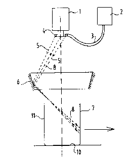
Figure 1 shows a video camera 1 and a light source
2 which gives off light by means of an optical conductor 3
via an end crown 4 of the light conductors. The light 5 coming
from these light conductors 4 is radiated into a container 7
via a conical mirror 6. The light 8 coming from the lighted
zone can be observed from approximately the same direction by
the video camera 1. The drawn rays 5, 8 indicate one lighting
and inspection zone only by way of example.
Figure 2 shows a video image 9. The video camera 1
"sees" the bottom of the can directly, as well as the standing
inner wall 11. The video camera 1 further inspects the inner
wall 11 via the conical mirror 6. This image zone is desig-
nated in figure 2 by 11'. It wil] be apparent that the use of
the conical mirror 6 achieves as it were an optical enlarge-
ment of the standing wall whereby the resolving power of the
optical system is better utilized. This is to the benefit of
the detection sensitivity.
By making use of a curved mirror instead of the
conical mirror 6 a still further effective enlargement can be
achieved.
Figure 3 shows a disposition wherein a light source
12 lights the inner surface 11 of the can 7 via a semi-trans-
parent mirror 13. The light source 12 is placed in relation
to the video camera 1 and the semi-transparent mirror 13 such
that the optical centre point of the lens system of the ca~era
1 coincides with the effective location of the light source
.. ` . ' . .: : "
;. ' ' ' :, '
,`~: , . . '-
~: ' ` , . ` , ' . '` ' ' , , ' ` . ' ' ' ` ` ':
.' :, ' ' ` . ' . ''' , .
' :`' '' ~ ' ' ' . , :
:: `' ` : .~, ,
. .

2002569
of the lamp 12.
Figure 4 shows an arrangement wherein a stroboscopic
lamp 14 lights the inside 11 of the can 7 via a three-sided
pyramid 15 via a concave mirror 16. The video camera 1 is
disposed relative to the mirror 16 such that here too the
lighting direction and the inspecting direction of the video
camera at least approximately coincide.
Figure 5 shows a top view from which can be seen
that three video cameras 1, 1' and 1'' are present, whereby
the total inner surface 11 of the can 7 can be inspected at
once. It is apparent that the embodiments according to figures
1 and 3 can inspect the entire inner surface with only one
video camera, while the arrangement according to figures 4
and 5 needs three cameras therefor. It is however noted that
the resolving power of the arrangement according to figures 4
and 5 can be correspondingly greater. The one or the other
arrangement may be preferred, depending on the desired sen-
sitivity of detection.
It is generally noted that the form of the mirrors
used can be chosen with a view to the desired result.
The use of the semi-transparent mirror according to
figure 3 can have the drawback that the quantity of light
available is effectively reduced. As compensation use could
be made for example of a stronger light source.
*****
: .- -,, , ~ . . . .
'.' ' ' - , ~, '
: ., . , :
, ., : .
: . . .~ . . .
, -

Dessin représentatif
Une figure unique qui représente un dessin illustrant l'invention.
États administratifs

2024-08-01 : Dans le cadre de la transition vers les Brevets de nouvelle génération (BNG), la base de données sur les brevets canadiens (BDBC) contient désormais un Historique d'événement plus détaillé, qui reproduit le Journal des événements de notre nouvelle solution interne.

Veuillez noter que les événements débutant par « Inactive : » se réfèrent à des événements qui ne sont plus utilisés dans notre nouvelle solution interne.

Pour une meilleure compréhension de l'état de la demande ou brevet qui figure sur cette page, la rubrique Mise en garde , et les descriptions de Brevet , Historique d'événement , Taxes périodiques et Historique des paiements devraient être consultées.

Historique d'événement

Description Date
Inactive : CIB de MCD 2006-03-11
Inactive : Abandon.-RE+surtaxe impayées-Corr envoyée 1996-11-11
Inactive : Demande ad hoc documentée 1996-11-11
Demande non rétablie avant l'échéance 1993-05-09
Le délai pour l'annulation est expiré 1993-05-09
Inactive : Demande ad hoc documentée 1992-11-09
Réputée abandonnée - omission de répondre à un avis sur les taxes pour le maintien en état 1992-11-09
Demande publiée (accessible au public) 1990-05-28

Historique d'abandonnement

Date d'abandonnement Raison Date de rétablissement
1992-11-09
Titulaires au dossier

Les titulaires actuels et antérieures au dossier sont affichés en ordre alphabétique.

Titulaires actuels au dossier
HEUFT-QUALIPLUS B.V.
Titulaires antérieures au dossier
MARCELLINES J. J. OBDEIJN
Les propriétaires antérieurs qui ne figurent pas dans la liste des « Propriétaires au dossier » apparaîtront dans d'autres documents au dossier.
Documents

Pour visionner les fichiers sélectionnés, entrer le code reCAPTCHA :


Pour visualiser une image, cliquer sur un lien dans la colonne description du document. Pour télécharger l'image (les images), cliquer l'une ou plusieurs cases à cocher dans la première colonne et ensuite cliquer sur le bouton "Télécharger sélection en format PDF (archive Zip)" ou le bouton "Télécharger sélection (en un fichier PDF fusionné)".

Liste des documents de brevet publiés et non publiés sur la BDBC .

Si vous avez des difficultés à accéder au contenu, veuillez communiquer avec le Centre de services à la clientèle au 1-866-997-1936, ou envoyer un courriel au Centre de service à la clientèle de l'OPIC.


Description du
Document 
Date
(aaaa-mm-jj) 
Nombre de pages   Taille de l'image (Ko) 
Revendications 1990-05-27 1 40
Abrégé 1990-05-27 1 26
Dessins 1990-05-27 2 29
Dessins représentatifs 1990-05-27 1 5
Description 1990-05-27 4 157
Taxes 1991-12-23 1 24
Correspondance 1992-02-27 1 37