Note: Descriptions are shown in the official language in which they were submitted.
2 0 0 2 7 ~ 3 23422-117
The invention relates to a device for connecting
accessory parts to formwork panels, compensating members and such-
like formwork members having stiffening webs or stiffening profiles
on their side remote from the forming surface. The device has an
essentially U-shaped cross section, the U-arms having fastening
locations for accessory parts such as booms or the like, and in
the position of use the U-crosspiece butts against a stiffening
profile of the formwork.
Formwork for circular constructions is known from
German Patent Specification No. 33 33 619, in which a chain of ties
adjustable in length is provided on the girders shoring the forming
surface. These ties in each case engage the girders of the form-
work panels by way of connecting pieces having an approximately
U-shaped cross section. These connecting pieces have fastening
locations for individual ties in their U-arms remote from the
formwork.
However these connecting pieces require further
coupling members for engaging the stiffening girders or stiffening
profiles, such coupling members being approximately U-shaped and
embracing the stiffening girders. However, it is not possible for
any accessory parts, such as stays directed towards the base,
brackets or the like, to be fasten~d with these connecting pieces
because they remain firmly connected to the individual ties.
The object underlying the invention is to create a
device of the kind mentioned at the outset, with which any accessory
parts such as booms, brackets, stays and the like can be fastened
'' 2032723
234422-117
to formwork panels quickly, simply and without any difficulty,
whilst it is possible for the stiffening webs or stiffening pro-
files to be selectively oriented either vertically or horizontally.
This seemingly contradictory object is accomplished
in a device of the kind mentioned at the outset in that at least
one of the U-arms has an extension extending over at least part
of its length and beyond the U-crosspiece on that side of the U-
arms which faces the forming surface in the position of use. This
extension is provided as protection against torsion and is adapted
to be placed against a longitudinal side face of the stiffening
profile and against the edge or bend at the transition from a
rearward web to the longitudinal side face of said stiffening
profile. The U-crosspiece of the device has at least one hole for
the passage of a shank of a fastening member, said fastening member
having a head or the like projecting radially beyond the shank,
at least to one side, and being adapted to be inserted into the
stiffening profile, from the side remote from the forming surface,
through an opening in the stiffening profile, and to be anchored
to the latter with its head. At the end of the fastening member
remote from its head it is provided with a counter-stop for
anchorage to the U-shaped device.
In a seemingly inconsistent manner at least one of
the U-arms of U-shaped device projects beyond the U-crosspiece,
but thereby permits torsion-proof coupling onto the stiffening
profile with the aid of the fastening member. Therefore any
accessory parts can in turn be fastened to this device without any
difficulty, and without any additional measures for such
2002723
protection against torsion.
This invention relates to a device for connecting
first and second formwork components to one another,
comprising a joining element which includes a pair of spaced
legs each having a first portion and a second portion, and a
crosspiece connecting said legs to one another, said cross-
piece being arranged such that said first portions project
beyond a first side of said crosspiece and said second
portions project beyond an opposite second side of said
crosspiece to thereby permit said second portions to embrace
part of the first formwork component and prevent relative
rotation of the first formwork component and said joining
element when the first formwork component and said joining
element have a first relative orientation, at least one of
said second portions having a shoulder for abutment with the
first formwork component in a second relative orientation of
the first formwork component and said joining element so as to
prevent relative rotation of the first formwork component and
said joining element when the first formwork component and
said joining element have said second relative orientation;
and a fastening element for securing the joining element to
the first formwork component, said fastening element including
first means for urging said joining element and the first
formwork component towards one another and second means for
establishing a connection with said joining element, and at
least one of said first portions being provided with
connecting means for establishing a connection with the second
formwork component, said fastening element comprising a shaft
-- 3
23422-117
B
-
2002723
and said first means including a head on said shaft for
abutment with the first formwork component so as to urge the
latter towards said joining element, said head projecting
radially outward of said shaft and being hammer-shaped so that
said head can be passed through a slot in the first formwork
component when said head has a first orientation and can
engage the first formwork component behind the slot when said
head is rotated from the first orientation to a second
orientation, and said second means being spaced from said
head.
This invention also relates to a device for
connecting first and second formwork components to one
another, comprising a joining element which includes a pair of
spaced legs each having a first portion and a second portion,
and a crosspiece connecting said legs to one another, said
crosspiece being arranged such that said first portions
project beyond a first side of said crosspiece and said second
portions project beyond an opposite second side of said
crosspiece to thereby permit said second portions to embrace
part of the first formwork component and prevent relative
rotation of the first formwork component and said joining
element when the first formwork component and said joining
element have a first relative orientation, at least one of
said second portions having a shoulder for abutment with the
first formwork component in a second relative orientation of
the first formwork component and said joining element so as to
prevent relative rotation of the first formwork component and
said joining element when the first formwork component and
- 3a -
23422-117
B
-
2002 723
said joining element have said second relative orientation;
and a fastening element for securing the joining element to
the first formwork component, said fastening element including
first means for urging said joining element and the first
formwork component towards one another and second means for
establishing a connection with said joining element, and at
least one of said first portions being provided with
connecting means for establishing a connection with the second
formwork component, said crosspiece being provided with
receiving means for said fastening element.
This invention further relates to a device for
connecting first and second formwork components to one
another, comprising a joining element which includes a pair of
spaced legs each having a first portion and a second portion,
and a crosspiece connecting said legs to one another, said
crosspiece being arranged such that said first portions
project beyond a first side of said crosspiece and said second
portions project beyond an opposite second side of said
crosspiece to thereby permit said second portions to embrace
part of the first formwork component and prevent relative
rotation of the first formwork component and said joining
element when the first formwork component and said joining
element have a first relative orientation, at least one of
said second portions having a shoulder for abutment with the
first formwork component in a second relative orientation of
the first formwork component and said joining element so as to
prevent relative rotation of the first formwork component and
said joining element when the first formwork component and
- 3b -
23422-117
B
~ -
2002723
said joining element have said second relative orientation;
and a fastening element for securing the joining element to
the first formwork component, said fastening element including
first means for urging said joining element and the first
formwork component towards one another and second means for
establishing a connection with said joining element, and at
least one of said first portions being provided with
connecting means for establishing a connection with the second
formwork component, the first formwork component including a
stiffener having a pair of spaced arms and a transverse
element connecting the arms to one another, the transverse
element having first receiving means for said fastening
element, and the first receiving means being spaced from each
of the arms by a predetermined distance as considered in a
direction from one of the arms to the other, said crosspiece
having second receiving means for said fastening element, and
said second receiving means being spaced from said shoulder by
said predetermined distance as considered in a direction
parallel to said legs and said crosspiece so as to permit
alignment of the first receiving means and said second
receiving means when said shoulder abuts the first formwork
component.
This invention relates to a device for connecting
first and second formwork components to one another,
comprising a joining element which includes a pair of spaced
legs each having a first portion and a second portion, and a
crosspiece connecting said legs to one another, said
crosspiece being arranged such that said first portions
- 3c -
23422-117
B
2002723
project beyond a first side of said crosspiece and said second
portions project beyond an opposite second side of said
crosspiece to thereby permit said second portions to embrace
part of the first formwork component and prevent relative
rotation of the first formwork component and said joining
element when the first formwork component and said joining
element have a first relative orientation, at least one of
said second portions having a shoulder for abutment with the
first formwork component in a second relative orientation of
the first formwork component and said joining element so as to
prevent relative rotation of the first formwork component and
said joining element when the first formwork component and
said joining element have said second relative orientation;
and a fastening element for securing the joining element to
the first formwork component, said fastening element including
first means for urging said joining element and the first
formwork component towards one another and second means for
establishing a connection with said joining element, and at
least one of said first portions being provided with
connecting means for establishing a connection with the second
formwork component; and a locking element arranged to bear
against said fastening element and against said joining
element so as to lock said fastening element to said joining
element.
This invention also relates to a device for
connecting first and second formwork components to one
another, comprising a joining element which includes a pair of
spaced legs each having a first portion and a second portion,
- 3d -
23422-117
B
-
2032 723
and a crosspiece connecting said legs to one another, said
crosspiece being arranged such that said first portions
project beyond a first side of said crosspiece and said second
portions project beyond an opposite second side of said
crosspiece to thereby permit said second portions to embrace
part of the first formwork component and prevent relative
rotation of the first formwork component and said joining
element when the first formwork component and said joining
element have a first relative orientation, at least one of
said second portions having a shoulder for abutment with the
first formwork component in a second relative orientation of
the first formwork component and said joining element so as to
prevent relative rotation of the first formwork component and
said joining element when the first formwork component and
said joining element have said second relative orientation;
and a fastening element for securing the joining element to
the first formwork component, said fastening element including
first means for urging said joining element and the first
formwork component towards one another and second means for
establishing a connection with said joining element, said
second means comprising a slit, and at least one of said first
portions being provided with connecting means for establishing
a connection with the second formwork component; and a locking
element for releasably locking said fastening element to said
joining element, said locking element comprising a wedge
receivable in said slit.
This invention further relates to a device for
connecting first and second formwork components to one
- 3e -
23422-117
,.~
. .
2002723
another, comprising a joining element which includes a pair of
spaced legs each having a first portion and a second portion,
and a crosspiece connecting said legs to one another, said
crosspiece being arranged such that said first portions
project beyond a first side of said crosspiece and said second
portions project beyond an opposite second side of said
crosspiece to thereby permit said second portions to embrace
part of the first formwork component and prevent relative
rotation of the first formwork component and said joining
element when the first formwork component and said joining
element have a first relative orientation, at least one of
said second portions having a shoulder for abutment with the
first formwork component in a second relative orientation of
the first formwork component and said joining element so as to
prevent relative rotation of the first formwork component and
said joining element when the first formwork component and
said joining element have said second relative orientation;
and a fastening element for securing the joining element to
the first formwork component, said fastening element including
a shaft, first means for urging said joining element and the
first formwork component towards one another and second means
for establishing a connection with said joining element, and
said first means including a head carried by said shaft, said
fastening element further comprising a locking member for
engagement in a slot of the first formwork component so as to
prevent rotation of said fastening element, and said locking
member being mounted on said shaft adjacent to said head, at
least one of said first portions being provided with
- 3f -
23422-117
20G2723
connecting means for establishing a connection with the second
formwork component.
This invention relates as well to a device for
connecting first and second formwork components to one
another, comprising a joining element which includes a pair of
spaced legs each having a first portion and a second portion,
and a crosspiece connecting said legs to one another, said
crosspiece being arranged such that said first portions
project beyond a first side of said crosspiece and said second
portions project beyond an opposite second side of said
crosspiece to thereby permit said second portions to embrace
part of the first formwork component and prevent relative
rotation of the first formwork component and said joining
element when the first formwork component and said joining
element have a first relative orientation, at least one of
said second portions having a shoulder for abutment with the
first formwork component in a second relative orientation of
the first formwork component and said joining element so as to
prevent relative rotation of the first formwork component and
said joining element when the first formwork component and
said joining element have said second relative orientation,
each of said first portions having a first end face directed
towards said second portions and a second end face directed
away from said second portions, and each of said first
portions being provided with a chamfer between the respective
end faces; a fastening element for securing the joining
element to the first formwork component, said fastening
element including first means for urging said joining element
- 3g -
23422-117
B~'
2002 723
and the first formwork component towards one another and
second means for establishing a connection with said joining
element, said second means comprising a slit disposed between
said first portions when said fastening element urges the
first formwork component and said joining element towards one
another, at least one of said first portions being provided
with connecting means for establishing a connection with the
second formwork component; and a locking element receivable in
said slit to lock said fastening element to said joining
element, each of said first portions being provided with
cutouts for said locking element and with connecting means for
establishing a connection to the second formwork component,
and said chamfers being spaced from said cutouts and said
connecting means.
The use of an extension extending over only part of
the length of the U-arms has the significant advantage that
the device can be fixed to the stiffening profiles also when
it is turned through 90~, i.e. with U-arms running
approximately at right angles to the longitudinal extent of
the stiffening profiles. Therefore these stiffening profiles
can run both horizontally and vertically and the device
according to the invention can be used for such formwork
panels as are to be usable in an orientation rotated through
90~, or which have intersecting stiffening profiles.
The fastening member for anchoring the device to a
stiffening profile may have a hammerhead which in one position
of orientation is adapted to be inserted through an oblong
hole in the cross web of the stiffening profile, and in the
- 3h -
23422-117
~'
200;2723
twisted condition - e.g. rotated through 90~ - engages behind
the edges of the oblong hole. This permits the device, and a
stiffening profile provided with corresponding oblong
openings, to be coupled particularly quickly and effectively.
For particularly effective protection against
torsion, together with the possibility of being able to
conduct forces and moments of commensurate magnitude into the
stiffening girders, and of being able to implement the device
with equal benefit in two positions rotationally displaced
through 90~, it is appropriate if both U-arms of the device
have extensions projecting beyond the U-crosspiece, and if
these extensions are shortened
23422-117
B
- 2002723
23422-117
relative to the total length of the U-arms so that they, together
with the U-crosspiece, form a shoulder - preferably an approximate-
ly steplike one - and are located beyond the ad~acent region of
the hole for the fastening member. In one fitting position, these
two extensions of the U-arms may engage over the longitudinal sides
of the stiffening profile and thus provide good and very secure
protection against torsion in both conceivable directions of
rotation, which permits the transfer of high forces and moments.
In a position rotationally displaced through 90~, the shoulders
of the shortened U-arms can bGth be placed against a common long-
itudinal side of a stiffening profile, which again provides pro-
tection against torsion and the possibility of transferring
moments, the distance of the two extensions from one another and
from the fastening member producing effective and torsion-proof
anchorage of the device onto the stiffening profile, the fastening
member thereby being secured in position relative to the stiffen-
ing profile at at least three points. This arrangement and
configuration of the device is therefore particularly desirable.
The shoulder between the U-crosspiece and the
extension of the U-arms may be placed against the longitudinal side
of the stiffening profile, and may be situated at that distance
from the hole for the fastening member which the oblong hole or
suchlike opening in the stiffening profile has from the edge of
the longitudinal web of this profile. It automatically follows
from this that the means protecting against torsion of the device
take effect in both fitting positions rotationally displaced
-' Z002723
23422-117
through 90~, because when fixed by the fastening member they butt
against the longitudinal side of the stiffening profile in each
case.
The better the device is urged against a stiffening
profile, the more effective is the protection against torsion. It
may be appropriate for this purpose if the counter-stop serving
for the fastening member and acting upon the U-crosspiece of the
device is adapted to be braced against the latter. This counter-
stop may engage the shank of the fastening member in a releasable
manner. In this way the counter-stop can also be affixed subse-
quently, when the fastening member and its head have been inserted
through the opening in the stiffening profile and twisted.
A transverse slit through the shank of the fasten-
ing member at the end thereof remote from the head, and a wedge
adapted to be inserted into the transverse slit, may be provided
as the counter-stop. In the position of use, the transverse slit
preferably extends right into the hole in the crosspiece of the
device. Thereby a concrete solution is simply provided for bracing
the counter-stop against the U-crosspiece of the device. The
wedge only has to be driven in deep enough to exert pull on the
shank, and thereby also on the head of the fastening member, in
order to urge the U-crosspiece of the device against that of the
stiffening profile.
In order to minimize the length of the fastening
member and thereby the overall size of the device, it is advan-
tageous if, in the position of use, the transverse slit in the
2002723
23422-117
shank of the fastening member is disposed between the U-arms of
the device on that side of the U-crosspiece which is remote from
the forming surface, and that the U-arms of the device have open-
ings at the level of the transverse slit for passage of the
anchoring wedge therethrough. The wedge can therefore be inserted
through these openings in order to reach its position of use in
the transverse slit of the shank of the fastening member.
In a further desirable embodiment of the device,
the cross section of the transverse slit for the wedge is arranged
on the shank of the fastening member at an angle - preferably 45~
- relative to the hammerhead of the latter, and the openings in
the U-arms of the device are arranged so as to be displaced in
such a way and/or extend laterally in such a way that the wedge
passes at an angle from the opening in one arm, through the anchor-
ing slit of the fastening member, to the other opening. The
wedge can therefore be driven in with a slanting fit in such a
manner as to be held in its position of use by gravity. This not
only makes fitting easier, but also counteracts any unintentional
loosening.
In a further advantageous embodiment the openings
for the wedge in the U-arms of the device extend laterally in such
a way, or so many openings are provided side by side, that the
wedge can be inserted from both sides at an angle to the surface
of the U-arms, in at least two positions preferably rotationally
staggered through 90~. This allows application of the device to
stiffening profiles in two positions varying by 90~, depending on
~- 2002723
23422-117
whether the stiffening profiles run approximately vertically or
horizontally. In each of these cases the wedge can pass from top
to bottom at an angle as opposed to horizontally, or even from
bottom to top.
The fastening locations for the releasable attach-
ment of accessory parts may take the form of recesses, preferably
holes, and may be arranged on the U-arms of the device, in spaced
relationship to the openings for the anchoring wedge. Mention is
however made at this point that a nut may also be provided by way
of a thread on the shank as a counter-stop, should the U-arms
not offer sufficient room for the openings for the wedge on the one
hand and for the fastening locations on the other hand.
A fastening location may be provided on each U-arm
and both fastening locations may preferably be of the same shape
and in a corresponding position, in particular taking the form of
bores for a bolt or the like. The latter can then traverse a por-
tion of an accessory part disposed between the two U-arms and can
be anchored to the U-arms on both sides of the engaged portion of
the accessory part.
The fastening member of the device is secured par-
ticularly simply and well if the surfaces of the head of the
connecting bolt which face the inside of the U-cross web of the
stiffening profile slant outwardly from the shank to conform with
a bead-like or channel-like depression of the U-cross web of the
stiffening profile. This at the same time increases the rigidity
of the stiffening profile, so that it better lends itself all to
~ 2002723
23422-117
the attachment of accessory parts by way of the inventive device.
It is expedient if the extensions of the U-arms
are integral therewith. The U-crosspiece of the device may be
fitted, particularly welded, between the U-arms and extensions
thereof, and its surface which rests against the outer web of the
stiffening profile in the position of use, may appropriately be
approximately flush with the non-extended area of the U-arms. This
produces a rigid design, particularly of the U-shaped part of the
device according to the invention.
Mention is made that the hole for the fastening
member is appropriately a bore, because this can be made particular-
ly simply and also accommodates a correspondingly simple round
shank of the fastening member. However this bolt-like fastening
member may have between its shank of preferably round cross
section and the angular surfaces arranged in a roof-shaped manner
on the underside of its head, a square area as protection against
torsion, the square area serving to engage the recess in the cross
web of the stiffening profile. This makes it easier for the trans-
verse slit for the anchoring wedge to retain its position after
the head of the fastening member has been inserted and fixed, and
thus makes it easier for the wedge to be inserted at an angle from
th~ side.
In order to save weight, the U-arms of the device
may be slanted between their end faces and their edges remote from
the crosspiece, the slants being beyond the openings for the
anchoring wedge and the holes for fastening accessory parts.
2002723
23422-117
A device, with which any accessory parts can be
attached to formwork members having corresponding stiffening webs
and stiffening profiles, whilst these accessory parts may be ad-
justable props, platform brackets, climbing brackets, supporting
jacks, base stays or booms, results from the features and steps
described above being combined singly or severally. The device
can be fitted in two positions, preferably rotationally displaced
through 90~, so that the device together with its U-arms and
fastening locations can in each case be oriented in such a way as
is required to attach the accessory parts, regardless of whether
the stiffening profiles of the formwork panels are oriented ver-
tically or horizontally. This device can also be arranged on floor
formwork with corresponding stiffening profiles. An efficient
and firm connection between the accessory parts and the formwork
member is produced in every position of attachment, it being pos-
sible for not only forces, but also moments to be transferred,
owing to the good protection against torsion.
The invention with its principal features is des-
cribed more specifically below in one exemplified embodiment with
the aid of the drawings in which,
Figure 1 is an exploded view of the device according
to the invention before being fitted to a horizontally oriented
stiffening profile of a vertical formwork panel/ and before having
an accessory part, in this case an adjustable prop, attached to it,
Figure 2 is a rear view of the device in the fitted
condition, the horizontal stiffening profile and the accessory
2002723
23422-117
part being omitted in the interest of clarity, but an oblong hole
in the stiffening profile being indicated,
Figure 3 is a section through the U-crosspiece of
the device and through that area of a stiffening profile which is
proximate to this device, as well as a view of a U-arm and the
extension thereof extending over only part of the length as pro-
tection against torsion,
Figure 4 is a side view of the entire device in an
orientation for engaging a vertical stiffening girder or stiffen-
ing profile and
Figure 5 is a top view of the device in a position
fitting a vertical stiffening profile, and in a position in which
the two extensions extending over only part of the length of the
U-arms of the device engage over the longitudinal side faces of
the stiffening profile as protection against torsion.
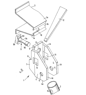
A device designated generally as 1 serves for
connecting accessory parts, for instance an adjustable prop 2, to
formwork panels, compensating members or suchlike formwork members
which are not shown in any detail in the drawings, and which have
stiffening webs,girders or stiffening profiles 3 on their side
averted from the forming surface. These stiffening profiles 3
are illustrated in complete cross section by way of example in
Figure 1, and in Figures 3 and 5 with regard to the portion co-
operating with the device.
It becomes clear by reference to Figure 1 and parti-
cularly Figure 5 that the device 1 has an essentially U-shaped
cross section and its U-arms 4 have fastening locations 5 for
-- 10 --
' 2002723
23422-117
accessory parts such as booms, adjustable props 2 or the like. In
the position of use the U-crosspiece 6 butts against the stiffening
profile 3 of the formwork, as illustrated in Figures 3 and 5.
In comparing Figures 2 and 3 on the one hand with
Figures 4 and 5 on the other hand it is apparent that engagement
can be made to a profile 3 by the device 1 in two different posi-
tions rotationally displaced through 90~, or that fixation to
profiles 3 varying 90~ in orientation is possible. At the same
time the device 1 is well protected against torsion relative to
the profile 3, so that the forces and moments to be transferred
can be adequately conducted.
This is achieved by providing the U-arms 4 with an
extension 7, in each case extending along part of their length and
beyond the U-crosspiece 6 on that side of the U-arms which faces
the forming surface in the position of use. These extensions 7
are provided as protection against torsion in both fitting posi-
tions. In accordance with Figures 3 and 5, these extensions 7 are
adapted to be placed in two different ways against the longitudinal
side face 3a of the stiffening profile 3 and against the edge or
bend at the transition from web 3b to the longitudinal side face
3a of the stiffening profile 3.
Additionally, the U-crosspiece 6 of the device 1
has a hole 8 for the passage of a shank 9a of a fastening member 9
also having a head 9b projecting radially beyond this shank 9a at
least to one side, and in the exemplified embodiment to two sides.
This fastening member 9 is adapted to be inserted into the
- 2002723
23422-117
stiffening profile 3, head 9b foremost, from the side remote from
the forming surface, through an opening 10 in the form of an
oblong hole in the stiffening profile 3, and to be anchored to the
latter with its head 9b in the manner shown in Figures 3 and 5.
The fastening member 3 has at the end remote from the head 9b, a
counter-stop yet to be described for anchorage to the U-shaped
device 1.
The fastening member 9 therefore has a hammerhead 9b
for anchoring the device 1 to a stiffening profile 3. In the one
orientation the hammerhead 9b is adapted to be inserted through
the oblong hole 10 in the cross web 3b of the stiffening profile
3 and then twisted through 90~ in the illustrated embodiment to
engaging behind the edges of the oblong hole 10, as indicated by
dashed lines in Figure 2.
In comparing Figures 3 and 5 it is apparent that both
U-arms 4 of the device 1 have extensions 7 stretching beyond the
U-crosspiece 6 and that these extensions are shortened relative
to the total length of the U-arms 4 in an identical manner and
so as to be of identical size. Together with the U-crosspiece 6
the extensions 7 form an approximately steplike shoulder 11 (cf.
particularly Figures 3 and 4) and are situated beyond the neigh-
bouring region of the hole 8 for the fastening member 9.
As shown in Figure 5 the extensions 7 can, with their
own longitudinal expanse, directly engage the longitudinal sides
3a of the stiffening profile 3 as protection against torsion when
the U-arms 4 and the stiffening profiles 3 have a conforming
- 12 -
2002723
23422-117
direction of orientation. In a fitting position turned through
90~, in accordance with Figures 1 to 3, the shoulder 11 between
U-crosspiece 6 and extension 7, or rather the shoulder 11 between
the non-extended area of the U-arms 4 and extension 7 of the U-
arms, can serve to prevent torsion against the longitudinal side
3a of the stiffening profile 3, as will be clearly apparent from
Figure 3. The shoulders 11 are situated at that distance from the
hole 8 for the fastening member 9 which the oblong hole 10 in the
stiffening profile 3 has from the longitudinal webs 3a of the
latter or the beginning thereof adjacent to the cross web 3b.
Therefore, the shoulders 11 produce the desired protection against
torsion and rest against the profile 3 in the position in which the
U-arms 4 of the device 1 are applied to the profile 3 when they
are rotationally displaced through 90~ relative to the longitudinal
direction of the latter.
The previously mentioned counter-stop for the fasten-
ing member 9 is adapted to be braced against the U-crosspiece 6 of
the device 1 and against the fastening member, in order to urge
the device 1 firmly against the profile 3 and to render operative
the means protecting against or resisting torsion. It is advan-
tageous if this counter-stop engages the shank 9a of the fastening
member in a releasable manner. In the illustrated embodiment it
is contemplated that a transverse slit 9c through the shank 9a of
the fastening member 9 at the end thereof remote from the head 9b
is provided, and that a wedge 12 fitting and being adapted to be
inserted into this transverse slit 9c is provided as the counter-
- 13 -
2002723
23422-117
stop. In the position of use, the transverse slit 9c extends
approximately into the hole 8 in the crosspiece 6 of the device
1. It is thereby ensured that, as the wedge 12 is driven in, the
narrow side thereof facing the U-crosspiece 6 comes to rest against
the U-crosspiece 6 and with the opposite narrow side can exert
the desired pull on the shank 9a.
So that the device 1 does not become too large in
size, and so that the lever arms applied to the profiles 3 by the
device are not too great, the transverse slit 9c in the illustrated
embodiment is disposed between the U-arms 4 and the U-arms 4 of
the device 1 have openings 13 at the level of the transverse slit
9c for the anchoring wedge 12. These openings extend sufficiently
far towards the formwork that the surface of the U-crosspiece 6
remote from the forming surface lies within the clearance of
openings 13, so that the wedge 12 can rest against this surface of
the U-crosspiece 6.
It is, however, also conceivable that the wedge may
rest against the corresponding edge boundaries of the openings 13,
particularly if and when the slit 9c does not extend right into
the hole 8 or even beyond it.
It is evident from Figure 2 that the cross section
of the transverse slit 9c for the wedge 12 is arranged on the shank
9a of the fastening member 9 at an angle of approximately 45~
relative to the hammerhead 9b of the latter. The openings 13 in
the U-arms 4 extend laterally in such a way that the wedge 12
passes at an angle from one arm 4, through the anchoring slit 9c,
- 14 -
~- 2002723
23422-117
to the other arm 4 and opening 13 thereof. The wedge can therefore
be arranged so as to pass from top to bottom at an angle in both
possible orientations of the device 1. This makes fitting easier,
because initial insertion of the wedge is aided by gravity.
Furthermore the position of use is also maintained and secured
better by gravity, and a wedge 12 is prevented from unintentionally
dropping out. In addition, a retaining pin 14 may be provided at
the narrow end of the wedge 12.
The openings 13 extend laterally in the longitudinal
orientation of the U-arms 4 to such an extent that the wedge 12
can be inserted from both sides, at an angle to the surface of the
U-arms 4, in two positions displaced 90~ from each other, so that
it is unnecessary to pay any attention to the position of the
transverse slit 9c when the fastening member 9 is inserted before-
hand. Instead of correspondingly enlarged recesses or openings
13, several openings 13 side by side could also be provided in
order to permit these two angular positions of the wedge 12.
In the illustrated embodiment, the fastening loca-
tions 5 take the form of recesses or holes and are arranged on
the U-arms 4 of the device 1, in spaced relationship to the open-
ings 13 for the anchoring wedge 12. Figure 1 makes it clear that
a fastening location 5 is provided on each U-arm 4 and both
fastening locations 5 are of the same shape and in corresponding
locations. Both fastening locations take the form of, e.g. bores
for a bolt, which also passes through corresponding bores 15 in
the adjustable prop which, in turn, can be fitted between the two
-- 15 --
- 2002723
23422-117
U-arms 4. Therefore the coupling area and corresponding fastening
location 15 of this adjustable prop 2 or of any other accessory
part can be inserted between the U-arms 4 and anchored there using
a bolt through all the fastening locations 5 and 15. The adjust-
able prop can then absorb or transfer forces and moments which
can be conducted by the device 1 into the profiles 3 in a desirable
manner, without any risk of twisting or deflection. Conversely,
forces emanating from the profiles 3 and the formwork panels can
thus be transferred by way of the device 1 to such adjustable prop
2 or the like.
Although other solutions are also possible, the illus-
trated embodiment contemplates that the extensions 7 of the U-arms
4 are integral therewith. The U-crosspiece 6 of the device 1 is
fitted and welded between the U-arms 4 and extensions 7 thereof,
its surface resting against the web 3b of the stiffening profile 3
in the position of use preferably being approximately flush with
- or according to Figure 4 even jutting out slightly from - the
non-extended area of the U-arms 4.
In the illustrated embodiment the hole 8 for the
fastening member 9 is a bore, which is particularly easily made.
Figure 1 shows that the bolt-like fastening member
9 has between its shank 9a of round cross section and the angular
surfaces arranged in a roof-shaped manner on the underside of
its head 9b, a square area 9d as protection against torsion or
twisting the square area 9d engaging the recess 10 in the cross
web 3b of the stiffening profile 3. The angular surfaces on the
- 16 -
-- 2002723
. 23422-117
head 9b as well as this squared area 9d therefore stabilize the
position of the fastening member 9, and thereby that of the wedge
and of the entire device 1, and thus improve the transfer of forces
and moments.
It is furthermore apparent from Figure 1 that the U-
arms 4 of the device 1 may be slanted between their end faces 4a
and their edges 4b remote from the crosspiece 6, the slanted
edge being beyond the openings 13 for the anchoring wedge 12 and
the holes 5 for fastening accessory parts 2. Weight is thereby
saved and inconvenient projection of the device 1 relative to the
profiles 3 and accessory parts 2 is limited as much as possible.
A device 1 serves for connecting accessory parts 2
to formwork panels, compensating members or suchlike formwork
members having stiffening webs or stiffening profiles 3 on their
side remote from the forming surface. The device 1 has an essen-
tially U-shaped cross section, the U-arms 4 having fastening
locations 5, preferably bores, for accessory parts 2 such as booms,
adjustable props, platform brackets or the like, and, in the
position of use, the U-crasspiece 6 butting and being drawn tight
against a stiffening profile 3 and primar:ily against a cross web
3b provided on the latter. At least one of the U-arms 4, prefer-
ably both U-arms 4, has an extension 7 extending over part of its
length and beyond the U-crosspiece 6 on that side of the U-arms
which face the forming surface in the position of use, such
extension being provided as protection against torsion and being
adapted to abut the longitudinal side face 3a of the stiffening
2002723
23422-117
profile 3 and the transition from the rearward web 3b to the longi-
tudinal side face 3a. The U-crosspiece 6 of the device 1 has at
least one recess or hole 8 - possibly even one open at the edge -
for a fastening member to engage, preferably for the shank 9a of
a fastening member 9 to pass through. It is thereby possible for
the device 1 to be anchored - in a torsion-proof position and in
two orientations rotationally displaced through 90~ - to a stiffen-
ing profile 3, so that the forces and moments encounted can be
transferred well.
One embodiment of significance to the invention is
apparent primarily in Figure 5 and also in Figure 2. According to
these, the extensions 7 are set somewhat at an angle to one another
in comparison to the parallel U-arms 4, so as to conform to the
trapezoidal shape of the stiffening profile 3 and the corresponding
slanting orientation of the cross section of the side webs 3a of
the stiffening profile 3. The inside dimensions of these exten-
sions 7, set somewhat at an angle to one another, correspond to
the outside dimensions of the two longitudinal webs 3a of the
stiffening profile 3.
It is also apparent in the Figures that, in the posi-
tion of use, the narrower area of the wedge 12 traverses a U-arm
and recess 13 thereof, but the wider area of the wedge passes by
the outside of the opposite U-arm and end face thereof or is
even supported against the latter. It is therefore not necessary
for the wedge to traverse both recesses 13 simultaneously, but
always only one of them selectively.
- 18 -