Note: Descriptions are shown in the official language in which they were submitted.
200289~
HIGH SPEED CONTACT SEALER
BACKGROUND OF THE INVENTION
This invention relates to apparatus for the
manufacture of elongated tubular film products from length of
flexible, flat films, and more particularly, to a high speed
contact sealer.
Consumer products such as meat products and
especially sausage are formed in elongated, closed end tubes
known as chubs. Chubs and similar containers have been formed
serially from filled, elongated tubes of film. The elongated
tubes of film have been formed by machinery from rolled
lengths of flexible, flat film. Such machinery of the past
has been valuable, but limited in high speed capacity.
Known machines for manufacturing closed film product
from flat film include intermittent heating units such that
flat film ls formed over a formlng shoulder lnto rolled film
having an overlapping seam, which rolled film ls then paused
in its movement. With the fllm paused, a heatlng bar ls
brought to bear against the seam of the film. The heating bar
seals the seam. After such heating, the film is advanced to a
distance such that a next section of unsealed film is
available for heating again.
SUMMARY OF INVENTION
In a principal aspect, the present invention
constltutes improved apparatus for the manufacture of a length
61368-855
2002894
of closed fllm product form a length of flexlble, flat fllm
comprlslng, in combination: (a) a support frame; (b) a form
member supported at one end by the frame and extendlng as a
cantllever beam, generally horlzontally, and deflnlng an axls;
~c) a fllm form collar surroundlng the form member, sald fllm
form collar constructed to fold the sldes of a flat strlp of
fllm one over the other to thereby deflne a seam of a closed
fllm product, surrounding the form member; (d) means mounted
on the frame, for transportlng the closed fllm product axially
on the form member, sald means for transportlng comprlslng
flrst and second transport members posltloned on opposlte
sldes of the form member and contlnuously frlctlonally
engageable wlth film on the member and movable to transport
the film therewith axially on the form member, and sald means
for transportlng further comprlslng means for synchronously
driving the first and second transporting means; and (e) heat
seal means mounted on the frame and lncluding a solid, closed
loop, movlng band posltlonable over the seam to engage the
seam for heat and pressure transfer to the fllm, sald heat
seal means further comprlslng means for drlvlng the movable
band ln synchronlzation wlth the flrst and second transport
means for slmultaneous movement of the seam wlth the film on
the form member; (f) means for posltlonlng the closed loop,
movable band over the seam to engage the seam; the flrst and
second transport members belng posltloned axlally ln posltlons
substantlally axially centered on the closed loop, moving band
of the heat seal means.
61368-855
2002894
- 2a -
A principal obiect of the invention ls an apparatus
capable of speed not previously achieved and including 500
feet per mlnute of product.
These and other objects, aspects and advantages of
the invention will be described in relation to the preferred
embodiments of the lnventlon, under the heading Detailed
Descriptlon Of The Preferred Embodlments, as follows.
BRIEF DESCRIPTION OF THE DRAWINGS
In the followlng Detailed Descriptlon of the
Preferred Embodlments, two preferred embodlments of the
inventlon are described. These two embodiments are depicted
in the accompanylng drawlng, the flgures of whlch are each as
follows
FIG. 1 is a side elevation view of the apparatus of the
first preferred embodiment;
FIG. 2 ls a plan vlew of the apparatus of the flrst
preferred embodiment;
FIG. 3 ls an exlt-end elevatlon view of the apparatus of
the first preferred embodiment;
61368-855
~ zoo~
- 3 -
FIG. 4 ia a schematic, perspective view of the
apparatus of the rirst preferred embodiment;
FIG. 5 is a view of the product formed from the
film handled by the apparatus of the fir~t preferred
s embodiment;
FIG. 6 i8 a cross-section of the product of FIG.
5, excluding contents, ~howing the ~eam sealed by the
apparatus;
FIG. 7 is an exploded per~pective view of a
form-tube-to-fill-tube ~olnt of the apparatus of the
rirst preferred embodiment;
FIG. 8 i8 a cross-section Or a film tension
regulator of the ~irst pre~erred embodiment, the cross-
section being taken along line 8-8 in Figure 9;
FIG. 9 i8 a perspective view of the film tension
regulator of the first preferred embodiment;
FIG. 10 is a collection Or three schematics view
of a flag and an eye mark employed in the first
preferred embodiment to synchronize the first preferred
embodiment with a rotary stuffing machine used in
a~sociation with the ~irst preferred embodiment, with
the flag and mark in condition Or ~ynchronization at
the top of Figure 10, with the flag and mark in
condition reguiring less drag from the film tension
regulator of Figure~ 8 and 9 in the middle of Figure
10, and with the flag and mark in condition requiring
more drag at the bottom of Figure 10;
FIG. 11 is a partial perspective view of the
~ore tube, heat ~ealing unit and transport mechanism of
the first preferred embodiment;
FIG. 12 is a partial perspective view of the
heat sealing unit, transport mechanism,
and film advancing mechanism of the first preferred
embodiment;
Z00~8~
- 4 -
FIG. 13 ia a ~ide elevation view, similar to
Flgur- 1, of the ~ d and more preferred embodiment
ot the invention;
FIG. 14 i8 a broken, partially cross-sectioned
view of the ~upport ~tructure of the heat sealing unit
of the ~econd preferred embodiment;
FIG. 15 1~ a partial, ~ldo elevation view of a
spring-loaded bearing bloc~ of the heat sealing unit of
the second preferred embodiment;
FIG. 16 i8 a cross-sectional view of film about
the form tube of the s~:~n~ preferred embodiment;
FIG. 17 i8 an exploded perspective view of a
form-tube-to-fill-tube ~oint of the ~econd preferred
embodiment of the invention, similar to Figure 7;
FIG. 18 i8 a cross-section of a film tension
regulator of the ~econ~ preferred embodiment, similar
to Figure 9;
FIG. 19 is a side elevation view of an inner
ring of the film tension regulator of the second
preferred embodiment;
FIG. 20 is an end elevation view of the inner
ring of Figure 19;
FIG. 21 i~ a cro~s-section view of a closed-loop
belt of the film advancing mechanism of the second
preferred embodiment of the invention, depicting the
~hape of the preferred shirring finger of the belt;
FIG. 22 is a perspective, detail view of an
idler roller ad~ustment of the first and second
pr-ferred embodiments, and a dot scanner of the second
preferred embodiment of the invention;
FIG. 23 i5 a perspective, detail view of a
plate-locating pin and toggle clamp as~ociated with a
plate 26 of the first preferred embodiment and the
second preferred embodiment;
20028~4
-- 5 --
FIG. 24 is a broken, end view of a film loading
and ad~ustment mechanism of the second preferred
embodiment; and
FIG. 25 is a broken, side view of the mechanism
of Flgure 24.
DETATT~n n~-CCRIPTION OF THE ~ ~KK~U EMBODIMENT
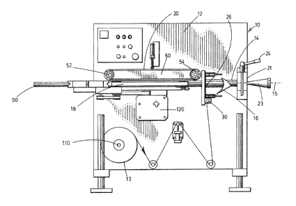
Referring to Figure 1, the first preferred
embodiment of the invention i~ one form of an improved
apparatus 10 for the manufacture of a length of closed
film product from a length of flexible, flat film 13.
The apparatus comprises, in combination, (a) a support
frame 12, (b) a form member 14 supported at one end by
the frame 12 and extending as a cantilever beam,
generally horizontally, and defining an axis 15; (c) a
film form collar 16 ~urrounding a section of the form
member 14, said film form collar 16 constructed to
fold the sides of the flat strip of film 13 one over
the other around the form member 14; (d) a transport
mechanism 18, mounted on the frame 12, for transporting
the closed film product axially along the form member
14; and (e) a h-at seal mechanism 20 mounted on the
frame 12 and positionable over the seam to engage the
seam for heat and pressure transfer to the film 13 and
simultaneous movement of the seam with the film 13 on
the form member 14.
A chuck 21 holds in cantilever fashion, and in
cG.._entric fashion, a meat product di~charge horn 23
and opposite thereto, the form member 14 in the form of
a forming tube. The chuck 21 includes a quick release
mechani~m 24 for rapid opening of the chuck, and
ther~by, change~ of the horn 23, the forming tube 14,
or both.
Ad~acent the chuck 21, the film form collar, or
"forming" collar 16 is held by a plate 26 and forms
Z00~8~
fl-xible, flat film 13 around the form member 14. The
forming collar 16 i8 arranged horizontally to receive
flexible, flat film 13 and form the film 13 so that
the film 13 exits the collar wrapped about the form
member 14, horizontally. The formed film 11 (see FIG.
6) i9 in the shape of a continuous cylinder, with one
longitudinal side of the film overlapped over the other
side of the film to define a seam 17.
The plate 26 i~ accurately machined and nests on
a set of locator pins mounted on plate supporting
brackets 29, such as pin 27 in Figure 23. The locator
pins are located about the brackets to abut points
along the periphery of the plate and provide for
concentric alignment of the forming collar or
"~houlder" 16 with the forming tube 14. The locator
pin~ are ne~ting pin~ and the plate nest~ again~t the
pin~. B~cause of the ne~ting, the plate automatically
and naturally comes to rest in a concentric position.
Release features are as~ociated with the plate 26 which
support the forming collar 16. The release features
allow for quick changes of the forming collar 16 to
adapt to films of different size~. Toggle clamps 28
(~ee FIG. 2 and FIG. 23) mounted on the plate
supporting brack-t provide the quick release of the
collar 16.
An idler roller 30 below the plate 26 allows the
ad~ustment of film tension on the forming shoulder 16.
Uniform tension and forming is maintained. Tension is
a matter of the stiffnQss of the particular film in
use. The idler roller 30 is located vertically
beneath the form fill shoulder 16 on ad~usting brackets
such as bracket 31 (cee FIG. 22) on the plate
supporting brackets 29 of the support frame.
Ad~ustment is vertical, through manual loosening of
bracket fasteners such as machine bolts, manual
Z0028~4
v-rtical positioning of the ad~usting brackets and
manual re-tightening of the fasteners. The ad~u~ting
brackets ars keyed to maintain vertical alignment so
that the axis of the idler roller 30 is always parallel
to the incoming surfaco of the forming shoulder 16.
After film 13 passes through the forming
shoulder or collar 16, lt continue~ on the form fill
tube in the region of contact heat sealing. A pair of
drive belts 40, 42 (FIG. 4) are positioned on opposite
sides of the tube along the longitudinal axis of the
tube. The drive belt~ draw the film forward along the
forming tube. The belts propel the film forward by
maintaining pre6sure contact on two ad~acent surfaces
on opposite sides of the film along the forming tube.
Floatable carriage arrangements such as 43 having
spring pressure maintain pressure uniformly along the
length based upon initial pressure pre~et in the
device.
The belts 40, 42 are not heated. The film is
engaged by friction of the rubber belt material against
the film. The belts are of ~light sponge nature to
conform to the shape of the forming tube. Opposed
drive belts are considered necessary to prevent film
skewing and improve film uniformity of tension. The
belts are driven through a drive shaft from below
through gear boxes and pulleys. A single mechanical
drive shaft drives both belts through the gear boxes
and drive pullefs. Single drive synchronizes the
b-lts. The belts are timing belts which prevent
slippage and continue complete control over the
longitudinal speed of the film as it pA~eE through the
region of the forming tube.
A heating unit 50 include~ a continuous closed-
loop band wrapped about two spaced pulleys 52, 54. The
lower surface of the belt, when placed in contact with
~002894
- 8 -
th- seam of the film, transfers heat to the seam,
thereby ~ealing the seam. The belt, two-spaced drive
pulley~ and heating unit therebetween are mounted above
the form filled tube in the heat sealing region. The
mounting i8 pivotal and provides for plaeement of the
lower surface Or the belt on the seam through pivoting
of the heating unit downward, and retraction of the
unit upward, under machine control.
A polytetrafluoroethylene (PTFE, trademark
TeflonR) cover 60 (FIG. 7) i8 placed on the form filled
tube beneath the film in the heat sealing area. The
PTFE cover surrounds the entire cireumference of the
form filled tube. The PTFE cover extends along the
form filled tube a length equal to the complete length
of the heat sealing unit.
Beneath the PTFE cover i8 a silicon padding 70.
The pad provides for slight deformation of the film
under the pressure of the heat sealing unit. The
pressure and slight deformity creates an area of
surface contact, as opposed to line contact, of the
heat sealing belt against the film seam. The heat
sealing belt is flat. The belt would normally come in
line eontact with the rounded tub~, but for the pad 70.
Line contact would result. The silicon, spongy
material is in a ~trip along the forming tube and does
not extend eireumferentially fully about the tube. The
deformation of the silicon strip converts the otherwise
line eontaet of the flat heat sealing belt against the
round tube to surface contact of the flat belt to a
flattened portion of the silieon pad and PTFE cover
about the tube. In addition to providing surface
eontaet of the tape against the film, the silicon
pres~ure pad distributes pressure and eliminates non-
uniformitiec of mechanical component~.
Z002(~
g
The closed-loop heat sealing belt i8 heated.
Ths belt moves in synchronization with the drive belts.
A ~-t of heaters are contained within the framework of
the heating unit. The heaters extend the entire length
of the framework, and are electric resistance heaters.
The entire ma~s of the framework is heated. The mass,
in turn, through contact with the belt, heats the belt.
Heat is transferred from the belt to the film.
The belt is a ~tainless steel band, PTFE coated
on the outside. The thickness of the belt and the
radius of the pulley~ of the heating unit are
interdependent, for maximum life of the belt, due to
the criticality of pulling stress, bending stress and
temperature effect~. The following eguation yields
pulley diameter if belt thickness i~ pre-selected, or
yield~ belt thickness if the pulley diameter is pre-
chosen.
/3 1-5 ~33btHD/V~aX) (1 - v~)(Dmin)
20 which
Tf - temperature factor
Sy - yield ~tress of the belt material at
room temperature, p~i
t - thickness of metal belt, inch
Hp - horsepower to drive metal belt
Vmax ~ maximum liner velocity of belt ft/min
E - modulus of elasticity psi
Dmin ~ smallest pulley diameter inch
b - width of metal belt
v - poisson's ratio
This equation offers 106 - 107 cycle life time
for most metal belt materials and the fatigue life of
200289~
-- 10 --
the belt is guite suitable for the application of the
eontaet sealer.
The preferred heat sealing unit with a sealing
ability up to 500 feet/minute needs approximately 1/5
driving horse power, and belt width of .25" for general
packaging. With ~ueh parameters, the equation
simplifies as follows:
Sy- Tf/3 - t (1 ~ V~)(Dmin)
For 301 high speed yield stainless steel, the following
parameters have the following values:
Sy ~ 260 k~i
Tf - .86
v - .3
E - 26 x 106 psi
The material of the metal belt ean be changed to others
such as 17-7 pH stainless steel, beryllium copper, 304
cold rolled stainless steel and the like, but for 301
high speed yield stainless steel, the relationship of
pulley diameter and belt thickness is as follows:
Sy- Tf/3 - 74533 ' 90t78 + 28.57 x 10⁶t
Dmin ' 28 57 x 106t2 inch
200Z89~
-- 11 --
D I A . I~CIl
~1. S ' 30~ ~l/CI~ Y~-0
Sr~NL~SS sr~L/
.0- /
.S
3.0
2.S'
2.0~
2 3 4 5 c 7 o~ 9 /o
BEL T T~lC~ SS /~ I~IL .
The flexible, flat film 13, when heat sealed,
absorb~ heat energy at a specific rate dependent upon
its materials. The film also requires a specific
amount of pres6urQ during fusing, also dependent upon
its materials. From these properties and from the
setting of a desired film speed, the length of the
heating unit i~ determined. The length of the heat
seal unit of the preferred embodiment is approximately
twenty inches, and the speed capability of the unit, as
intended, is approximately 500 feet per minute.
In contrast with prior art devices, the heat
sealing unit of the invention and especially the
preferred embodiment transfers heat to the film
continuously, continuously sealing the seam of the
film. Intermittent operation is not required, and is
avoided .
The pressure by which the closed-loop tape is
brought to bear against the film and the underlying
PTFE coating and silicon strip is determined by a
pneumatic cylinder. The pressure applied by the
cylinder is adjustable. Once a specific film is placed
~ Z00289~
- 12 -
for operation in th- machine, a constant pressure is
maintained. Ad~ustment is made only from film to film.
The amount of force to be brought to bear against the
film is directly determined by the film type, and is
available as a recommendation of the film
manufacturer.
The pulleys of the heating unit are driven by a
drive arrangement on the discharge end of the heating
unit. A timing belt is driven by the same driving
mechanism as drives the drive belts. The heat sealing
unit and the drive belts are synchronistically driven
for uniformity of speed of the drive belts and the heat
sealing tape. The heat sealing unit and the drive
belts are independently clutched, to provide for setup
of the machinery. In setup, the drive belts are placed
and film propelled along the forming tube. The heat
sealing unit is then brought to bear.
The film 13 has a tendency to shrink under
heating. The pressure of the heat sealing tape against
the seam prevents shrinkage in the area of the seam.
The film draws tightly about the tube. The forming
tube i8 sized to accommodate the shrinkage.
Because of the length of the heating unit and
the fact that it is heated, the heating unit has a
tendency to eYp~n~ longitudinally during operation.
Accommodation of expansion is provided in the mounting
of the heat sealing unit at its input end.
Accommodation is provided by a mounting which allows
the heat sealing unit and the mounting member attached
thereto to slide longitudinally along a cooperating
mounting member. Binding and buckling is prevented.
Mounting of a bracket attached to the heat sealing unit
along a longitudinally aligned pin is one possible form
of such a mounting.
Z002~39~
- 13 -
As most preforrQd, the heating unit includes
four embedded heaters. Heated material coats the
interface between the heaters and the heating unit
mass, to prevent oxidation and maintain the level of
heat energy reguired to sufficiently heat the heat
unit. All four heaters are provided electricity
through one circuit and temperature is controlled
through one thermocouplQ. Thermal mass of the heater
i8 chosen for thermal inertia such that control
variations in the apparatus are compensated as to the
seal of the seam by the thermal inertia of the heating
unit. Sealing i~ maintained despite such control
variations. Additionally, in sQtup, the he~ting unit
is preheated. When first brought to bear against the
fllm the heating unit loses heat energy. The inertia
of the heating unit allows the control circuitry of the
heating unit to add heat energy to the heating unit
sufficient to compensate for the initially lost heat
energy before so much heat energy i5 lost that the seal
of the seam i~ also lo~t.
A collar 80 interposes a fill pipe 90 and the
form tube. The fill pipe extend~ coaxially from the
form tube. The collar is split for placement about the
fill tube. The collar centers the fill tube with the
form tube. A plurality of openings are spaced
circumfarentially about the collar, and provide air
passage from the atmosphere to within the form tube.
Air pressure is equalized on both sides of the collar
to prevent a vacuum effect inhibiting forward motion of
the film as it leaves the form tube.
A casing brake mechanism (not shown) is adjacent
the remote end of the fill tube.
Between the heat sealing region of the form tube
and the casing brake, and along the fill tube, a film
advancing mechanism 100 includes two opposed, closed-
~ 2002894
- 14 -
loop belts 102, 104 having shirring fingers such as 108
foroed thereon. The transport mechanism (i.e., the
b-lt~ 40, 42) advances closed, sealed film from the
heat sealing region, and a~sures no back flow of film
into the heat sealing region. The ~hirring fingers are
flexible, and in positions of interference with the
fill tube. The shirring fingers sweep film along the
fill tube and allow the film to accumulate ad~acent the
casing brake for allowing the seal area to cool. The
two belts of the advancing r~ch~n~sm are synchronously
driven with the drive unit of the apparatus and the
heat sealing unit thereof. The shirring fingers, or
paddle blades, extend outwardly relative to the belts,
and are paired from belt to belt to be slightly
staggQred in relationship to each other as they advance
film along the fill tube. The belt~ are driven about
pulleys, the outer periphery of which are textured for
positive driving contact against the belts. Slippage
is prevented. A random stagger of the shirring fingers
is sufficient. The belts and pulleys Or the advancing
mechanism are po~itioned closely ad~acent the heat
sealing unit.
A supply of flat film 13 i8 rolled on a mandrel
110 (FIG. 4) below the heat sealing unit. The mandrel
or spool upon which the roll is placed is not driven,
but is braked to allow for the prevention o~ overspin
upon termination of machine operation. All driving of
th- film is under power of the driving units adjacent
the heat sealing unit. The mandrel is expandable to
lock the film roll to the mandrel shaft. Gross lateral
alignment of the film on the shaft is provided by the
manual placement and locking of the film on the shaft.
The film passes from the mandrel over an idler bar for
tension, then to an ad~ustable roller, which provides
for ad~ustment of tension of the film. The film as
2002894
- 15 -
rolled i8 not neeessarily uniformly tensioned, and
ad~ustment for tension for uniformity is desirable.
Laek of uniformity will skew the film. The ad~ustable
roller is a skewing roller, ad~ustable vertically about
a pivot to ad~ust tension laterally. The film
continues over another fixed roller and then upward
into the tensioning roller previously mentioned in
assoeiation with the forming eollar.
The earriage assembly 120 (see FIGS. 1, 2) for
the drive belts 40, 42 is aligned about the axis of the
form tube. An ad~u~ting nut allows eentering of the
carriage assembly relative to the axis. A hand crank
which rotates opposed lead serews then provides
movement of both drive units simultaneously inward and
outward relative to the form tube. Ad~ustment of
tension of the belt on the film against the form tube
is provided. Thus, both centering and drive pressure
ad~ustmQnt are provided.
The apparatus of the invention is employed with
a rotary platform maehine including a plurality of
clippers which rotate past the elosed, tubular film
exiting the apparatus of the invention, and form chubs
from the film and pumped internal material.
Registration and tensioning of film with the elippers
is provided by a film tension regulator as in Figures 8
and 9. The distanee between elippers is set slightly
longer than the desired length of the elosed film, the
l-ngth preferably being indieated by registration marks
202 (Figure 11) at regular intervals on the film.
Outside the filling horn i9 a PTFE ring 204 (Figure 8).
The outside diameter of the ring 204 i5 always less
than the fin~shed tube diameter (85 to 98 percent).
About the outside circumference of the Teflon ring is a
housing eontaining an O-ring 206 in a eaptive area.
About the out~ide of the captive area i~ an enlarged,
- 2002894
- 16 -
annular chamber. Air supplies are connected to the
chamber at several locations. The inside diameter of
the O-ring and ad~acent housing assembly inner, annular
edge i~ alway~ larger than 100 percent of finished tube
diameter. As the film passes through the space between
the ring 204 and the o-ring, a sensing circuit
determines when film i~ not on registration with the
clipper. An air pre~sure is supplied to the chamber
behind the 0-ring through a pneumatic circuit,
pressurizing the outside of the O-ring and displacing
it inwardly toward the film and ring. A compressive
force is applied to the film by pinching it to the
ring. By controlling the time of the compressive
force, stretch of the film is controlled. A feedback
circuit of the machinQ including a sen~or 210 (Figure
8) and a sensor on the rotary machine (not shown)
monitors the position of the clippere in space relative
to the flow of film into the rotary machine. If an
indicator mark on the film "reads" as it passes the
tensioning devico in synchronization with a flag on the
machine, then the film and clippers are in correct
relation~hip. The flag on the machine is indicated by
"CNT Flag" in Figure 10. A correct case is indicated
at the top. A case of clipper lateness relative to the
film iB indicated in the middle of the figure. A case
of clippers being early is indicated at the bottom.
With a late clipper, tension on the film is reduced.
With an early clipper, tension is increased.
Referring to Figure 13, the second and more
preferred embodiment of the invention is another form
of an improved apparatus 210 for the manufacture of a
length of closed film product from a length of
flexible, flat film 13. As with the first preferred
apparatu~ 10, the apparatus 210 includes a support
frame 12, a form member 14; defining an axis 15, a form
2002894
eollar 16, and a transport meehanism 18. The frame 12,
m~iber 14, eollar 16 and mechAn~sm 18 of the apparatus
210 are substantially identieal to like numbered
eomponents of the apparatus 10.
The apparatus 210 differs from the apparatus 10
in sQveral partieular~. First, a film loading and
ad~ustment mechanism 130 provide~ ~or advantageous
loading and ad~ustment o~ the film spool. A loc~ing
hub (not shown) is loeated on a mandrel 110 for loeking
the film spool on the mandrel. The hub includes three
eccentric member~ spaeed equally about the hub which
extend outward radially from the hub a~ the spool
rotates, to contact the spool core and wedge lock it
into position. Referring to Figures 24 and 25, a
cantilevered loading and adjustment support bracket 132
extends horizontally from the frame 12, transversely to
the form tube axis 15. The bracket 132 supports a
similarly extending film guide assembly 133, including
a pair of horizontally spaced guide arms such as arm
134 mounted along a film guide sleeve 135. The guide
arms are ad~ustably movable along the sleeve for
increasing and decreasing the distance between the
arms, to accommodate wider and narrower film spools.
The guide arms are also releasably swung upward (not
shown), away from the film spool for ease of mounting
of the spool on the mandrel 110. The sleeve is
laterally movable a]ong the assembly for ad~usting the
lateral or transvarse loeation of the eenterline of
spools.
The guide arms are ad~ustably movable and
releasably ~wung by manual release of split, clamping
ends 136 of the arms via handwheels 137, whieh drive
clamping screws such as screw 138; manual movement of
the arms; and manual re-tightening of the split
clamping ends via the handwheels. The sleeve 135 is
Z002894
- 18 -
lat-rally movable under action of internal screw
thread~ mating with external threads on a rotatable,
laterally fixed rod 139. Rotation of the rod 139 via a
handwheel 140 cause~ lateral movement of the sleeve.
Film guide roller~ 141 on cantilevered ends of the arms
ride the edge~ of the film core, after the film spool
is placed and the arms located about the spool.
A variety of film paths are available in
threading of the film on the apparatus 210.
Additional roller~ are mounted by bracket beneath the
carriage assembly 120 for greater variation of
threading. Additionally, a pivotable film fQstoon 142
includes rollers mounted on cantilevered festoon arms
144. The motion of the festoon i~ damped by a
pneumatic damper 146. As the apparatus 210 begin~
operation, the fe~toon rises to accommodate a lag in
the speed of the ~pool relative to the speQd of the
film under action of the tran~port mechAnism. As
speeds match between the fllm at the transport
mechanism and exiting the spool, the festoon lowers.
Referring to Figure 16, the forming tube 227 of
the second preferred embodiment has an outer diameter
slightly undersized (exaggerated in Figure 16 for
clarity) relative to the diameter to which the film is
to be formed. Opposed flats are located on the
forming tube 227, for improved contact by the drive
belts of the transport mech~nism. The flats are PTFE
coated. In an arc adjacent the band of the heating
unit, the forming tube is not undersized.
As the film moves onto the forming tube, after
leaving the forming collar, the film edges overlap a
greater distance than ultimately desired. To size the
film, the film is passed over a sizing ring, of
ceramic, which has the diameter desired for the film.
The sizing ring is juxtaposed immediately adjacent the
2()02894
-- 19 --
eontact point of the band of the heating unit, such
that immediately upon sizing of the fiim, the film
overlap is under pressure of the band, and bogins to
seal.
In tho aroa of the heat soal meehanism 220 of
the seeond preferred apparatu~ 210, and referring to
Figures 13 and 14, the heating unit 50 i~ mounted via a
slide mechA~ism 212 for linear, vertieal movement
betwoen po~itions of operation and retraction. When in
operation, the heating unit has its closed-loop band in
contact with the seam of film pa~sing along the form
~ilm tube. Vertical slidQ guide rods such as 214
extend from a plate 215 through a guido block 216. The
rods are slidable in th- bIock 216 and fastened to the
plate 215. The plate 215 is fixed to the hoating unit
250, the guide block 216 i8 rixed to a mounting bracket
213 to the frame 12, and under action of a vertically
acting slide cylinder 217, the rods, plate and heating
unit are driven vertieally upward and downward under
command of the apparatus control while~ the guide block
216 remains stationary. An end stop ad~ustment 218
provides for ad~ustment of tho torminal downward
position of tho hoating unit 250, to accommodate
variou~ film thickne~ses. The ond stop ad~ustment is
comprised of a threaded column faatened to the plate
215, pA~e~ loosely through an ad~ustment bloek 219 on
the guide bloek 216, and mounted by a pair of
v-rtically ad~ustable locking nuts. A pin-and-slot
parallol ad~ustmQnt between the heating unit 250 and
slide mQchanism 212 provides for parallel ad~ustment of
the heating unit 250 relative to the form member 14.
In the heating unit 250, as in the heating unit
50 of the apparatus 10, a continuous closed-loop band
or belt is wrapped about two spaced pulleys 52, 54. In
the unit 250, phenolic disks are mounted to the
Z002894
- 20 -
baek~idQs of the pullQys to insulatQ the pulley drive
m-chanism from h~at of the band transmittQd to the
pull-y~. Th- drive pulley 221, ~hown in Figure 12, i8
a glass reinforeed LQxanR pulley which insulatQs from
h~at of the band transferred along th~ drive shaft.
RefQrring to Figure 15, thQ idler pulley 54 in the
unit 250 is mounted to a spring-loaded bearing block
223. The bloek spring-biases the idler pulley 54 to
tighten the closQd-loop band, and is movable by spring
tQnsion, and by band tQnsion against 6pring ten~ion, to
maintain con~tant band ten~ion while the band
undergoQs temperature variations.
The hQating unit 250 includQs a central,
stainlQss st~el bloek 225, aa in Figure 15.
Electrieal rQsistanee h~aters are loeated within the
bloek 225, and brought into eontaet with the block by
heat ~ink compound. The exterior of the block 225
includes lateral heat shields, and a peripheral band
contaet faee whieh i~ nickel plated, PTFE impregnated,
and polishQd. The band is also PTFE eo~ted for eontact
with thQ band eontaet face. This combination of
matQrials provide~ for a lubricated contact of the
band with th~ band eontaet faee.
ThQ band eontaet faee has a width not greater
than the width of the band eontaet faee, and the face
i- di~tane~d from the eQntral portion of the bloek 225
bu a narrow-noekQd faee ~upport seetion. If film
blllows, at the sides of the moving band, the film
doQs not eontaet the bloek 225 due to the narrow-necked
fae~ support sQetion. This absenee of contact avoids
random heating and tearing of the film.
Ad~aeent the forming tube to fill tube union,
the forming tube is cutaway, as at loeation 229 in
Figure 17. The cutaway foreshortens the forming tube
relative to the heating unit, which has been found to
2C~2~9~
- 21 -
obvlate drag of the fllm on the formlng tube, and ellmlnatlng
skewlng of the fllm.
Static electrlclty between the lnner surface of the
movlng fllm and the PTFE coated formlng tube ls ellmlnated as
follows. Copper, conductlve staples are located along the
formlng tube, wlth crowns of the staples exposed along the
exterlor of the formlng tube. The legs of the staples extend
through the TeflonR coatlng, lnto contact wlth the metal tube
ltself. The tube ls grounded to the frame of the machlnery.
Standard englneerlng technlques are applled to other sources
of statlc electrlclty.
As ln Flgures 18-20, the PTFE rlng 324 of the fllm
tenslon regulator of the second preferred embodlment lncludes
a ramped portlon 326. The portlon 326 provldes for a smooth
transltlon of fllm off the flll tube and over the PTFE rlng.
The fllm tenslon regulator of each embodlment of the
lnventlon accompllshes reglstratlon of the fllm exltlng the
embodlment wlth a rotary platform machlne. A representatlve
rotary platform machlne ls dlsclosed ln U.S. Patent No.
4,821,485.
Speeds of the selected embodlment of the lnventlon
and the accompanylng rotary machlne are matched by a
controller whlch takes lnput from a sensor 328 and a sensor on
the rotary platform machlne. The sensor 328 recognlzes an eye
mark on the fllm as the eye mark passes the sensor. A slgnal
ls sent as each eye mark passes, and the controller
malntalns a count of the slgnals. The sensor of the rotary
.- f~
~ 61368-855
.
2002g~4
- 21a -
platform machine ls also statlonary, and recognlzes flags on
the machlne as they pass. A slgnal ls sent and a count
malntained. The two counts are compared, and any
'- -' li
,~
61368-855
2002894
- 22 -
dlrr-rence cau~-- an increase or decrea6e in speed of
th- lnvented device Thus, the rotary machine is the
ma~ter, and the invented device is the slave
Two prererred ~mbodiments of the invention are
now described To particularly point out and
distinctly claim the sub~ect matter regarded as
invention, the ~ollowing claims conclude this
specification