Note: Descriptions are shown in the official language in which they were submitted.
200.'21 1 ~9
A METHOD FOR PRODUCING CARBON-COATED OPTICAL FIBER
BACKGROUND OF THE INVENTlON
FIELD OF THE INVENTION
The present invention relates to a method for producing optical
fiber coated with a carbon layer.
PRIOR ART
Quartz-based optical fibers have been widely used for
communications cables. Hydrogen coming into contact with these fibers
disperses therein, and the molecular vibrations of the hydrogen lead to
greater absorption losses. In addition, the hydrogen diffused therein
may react with P2O3, GeO2, or B2O3, which are contained in the fiber as
dopants, and forming compounds with one or more OH groups.
Absorption by the OH group also increases absorption losses. One way
to solve these problems is to add a liquid-phase composition which can
absorb hydrogen in the fiber (Japanese Patent Application kokai No. 61 -
251808). However, this method is impractical: the produced fiber has a
limited capacity for hydrogen absorption and is structurally complex.
Corning Glass (International Wire & Cable Symposium Proceedings
1987, pages 241-244, and Journal of Lightwave Technology, Vol. 6, No.
2, February 1988, pages 240-244) and AT&T (Electronic Letters, 13th
October 1988 Vol. 24, No. 21, pages 1323-1324, and OFC '88/Tuesday
Afternoon/23) have recently disclosed that coating the fiber with
carbon by chemical vapor deposition (CVD) can enhance its resistance to
hydrogen. In the methods, an uncoated optical fiber prepared in a
spinning furnace is led to a hot CVD furnace, and then hydrocarbon
compounds are thermally decomposed to form a carbon layer on the
surface of the uncoated optical fiber in the CVD furnace. In the hot CVD
process, aqueous molecules absorbed on the surface of the uncoated
fiber are however dispersed in the core of the uncoated optical fiber,
and reacted with dopants which have been previously dispersed
therein. Accordingly, transmission loss is greatly increased in the
wavelength of 1.39 ~lm depending on the absorption of OH groups.
Also, aqueous molecules absorbed on the surface of the optical
fiber is reacted with the optical fiber at high temperature in steps of
forming carbon-coated layer on the surface of the optical fiber to form
- 1 - ~
200~1 1 ~
silanol groups. Also, hydrogen radicals, which are produced by
thermally decomposing the original hydrocarbon compound, cut the
siloxane bonds of composition of the optical fiber to form silanol groups.
The silanol groups erode the surface of the optical fiber to lead to
degrade mechanical properties thereof.
Furthermore, aqueous molecules absorbed on the surface of the
optical fiber lead to degrade deposition rate for carbon coating.
SUMMARY OF THE INVENTION
Accordingly, it is an object of the present invention to provide a
method for producing carbon-coated optical fiber having excellent
hydrogen-resistance and mechanical properties.
According to an aspect of the present invention, there is provided
a method for producing carbon-coated optical fiber comprising
(a) thermally decomposing a halogenated hydrocarbon
compound to obtain a thermal decomposate of the halogenated
hydrocarbon, and
(b) depositing the thermal decomposate on a surface of an
uncoated optical fiber to form at least one carbon coating layer on the
surface thereof.
DETAILED DESCRIPTION OF THE INVENTION
Halogenated hydrocarbons including ones which contain at least
one chlorine atom in molecule thereof, and/or ones whose hydrogen
atoms are totally substituted by halogen atoms can be used as starting
materials for thermally decomposition.
Typical Examples of such halogenated hydrocarbons containing at
least one chlorine atom include 1,2-dichloroethane, 1,1,1-
trichloroethane, 1,1,2,2-tetrachloroethane, 1,2-dichloroethylene,
monochlorobenzene, and the like.
Typical Examples of such halogenated hydrocarbons whose
hydrogen atoms are totally substituted by halogen atoms include
fluoride-containing halogenated hydrocarbons such as CF4, CClF3,
CC12F2, CC13F, CBrF3, C2C12F4, C2Br2F4, C2ClFs, C2F6, and the like.
The above-described halogenated hydrocarbons are thermally
decomposed to form chlorine radicals. The chlorine radicals react with
hydrogen atoms of aqueous absorbed on the uncoated surfaces of the
optical fiber to remove aqueous molecules from surfaces thereof.
200~1~9
Accordingly, the mechanical properties of the carbon-coated optical
fiber according to the present invention are improved because the
formation of silanol groups are regulated by removing aqueous
molecules to prevent the surfaces of the uncoated optical fibers from
erosion during the carbon layer deposition process.
Furthermore, removing aqueous molecules from the surface of the
optical fibers prevents aqueous molecules from diffusion from the
surface of the optical fibers to core thereof. Accordingly, the
transmission loss of the optical fibers caused by OH groups of aqueous,
which absorb energy of a specific wavelength, e.g., 1.39 ~,lm, is decreased
because the formation of the OH groups is reduced by virtue of the
remove of aqueous.
Also, all of halogen radicals generated by thermal decomposition
of halogenated hydrocarbons have sufficiently chemical reactivities, and
serve to remove compounds absorbed on the surface of the optical
fibers and to clean up thereon. Accordingly, the deposition of the
carbon coat is accelerated to increase the spinning rate of the optical
fibers .
In particular, fluorine radicals having high chemical reactivities
can remove fine flaws over the surface of the optical fibers by virtue of
etching operation thereof during deposition of the carbon coat. In this
case, mechanical strength of the optical fibers produced according to the
present invention are improved.
The carbon coat formed on the surface of the optical fibers
according to the present invention has properties of preventing
hydrogen from penetration from the outer surface to the inner one
thereof. Accordingly, high hydrogen-resistance of the optical fibers are
improved by virtue of the carbon coat thereof.
BRlEF DESCRIPTION OF THE DRAWINGS
The present invention will now be illustrated with reference to
the accompanying drawings wherein:
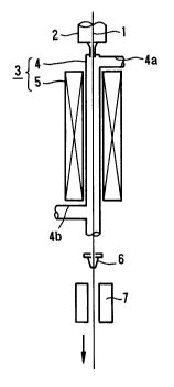
Fig. 1 is a perspective view showing an apparatus for producing
the carbon-coated optical fiber which is preferably used in the method
according to the present invention, and
Fig. 2 is a diagram showning the relationship between the
spinning rate of the optical fiber and the carbon coat thickness when
various starting compounds are used.
20()3119
DESCRIPTION OF THE PREFRRED EMBODIMENTS
In Fig. 1, reference numeral 1 denotes an uncoated optical fiber
which is produced by spinning a precursor (not shown) under heat in a
spinning furnace denoted by reference numeral 2. The uncoated optical
fiber 1 is then led to a hot CVD furnace 3, which is disposed beneath the
spinning furnace 2, and is subjected to coating a carbon layer over the
surface of the uncoated optical fiber 1 by CVD to form a carbon-coated
optical fiber.
The furnace 3 comprises a reactor tube 4 having substantially
cylindrical shape for performing and accelerating CVD reaction, and a
heater 5 for heating the reactor tube 4 to regulate CVD reaction. The
reactor tube 4 has an upper tube 4a for feeding a starting material for a
carbon layer to the reactor tube 4, and a lower tube 4b for exhausting
unreacted gasses to the ambient air. The heater 5 is disposed around
the reactor tube 4 so as to cover the surface of the reactor tube 4 with a
constant clearance between the reactor tube 4 and the heater 5. Typical
Examples of the heater 5 include a resistance heater, induction heater,
infrared heater and the like. Further, a type, which produces plasma by
high frequency waves or microwaves to ionize and decompose the feed
materials, may be used as the heater 5. Specifically, the heater 5 can be
selected from the above described groups depending on a temperature
region for heating the reactor tube 4 and for thermally decomposing the
feed compounds fed to the reactor tube 4.
The optical fiber is fed to the hot CVD furnace at a predetermined
rate so as to be passed on axes thereof. Simultaneously, the reactor
tube 4 is heated by the heater 5 at a predetermined temperature, and
the construction materials for carbon layer are fed through the upper
tube 4a to the reactor tube 4.
As previously described, typical Examples of the feed compounds
fed to the reactor tube 4 include halogenated hydrocarbon compounds
containing at least one chlorine atom in molecule thereof, and ones
whose hydrogen atoms are totally substituted by halogen atoms. In the
formers, halogenated hydrocarbon compounds are preferably of 15
carbon atoms or less in molecule thereof in the views of the properties
of the carbon layer over the uncoated optical fiber 1 and the carbon
deposition rate. The latters are easily handled because they are
- 4 -
2003~19
.
incombustible and because decomposition temperature thereof are
lower than that of the other.
The feed compounds may be fed in a gaseous state, or diluted
with inert gases such as argon gas and the like. The feed rate is
suitably determined depending on the type of the feed compounds and
the inner temperature of the reactor tube 4, and generally in the range
of from 0.2 to 1.0 I/min. The inner temperature of the reactor tube 4 is
determined so as to be included in a thermal decomposition
temperature region of the feed compounds, and generally in the range
of from 500 to 1200C, depending on the type of the feed compounds
and the spinning rate. When the inner temperature is below 500C,
thermal decomposate of the feed compounds is not performed and
accelerated. When the inner temperature is in excess of 1200C, large
quantities of soot is generated as a by-product, and simultaneously a
structure of the obtained carbon layer becomes similar to graphite
structure. In this case, the optical fiber having high hydrogen-
resistance cannot be unfortunately obtained. In order to prevent soot
from the formation thereof, the inner temperature of the reactor tube 4
may be kept so as to be slightly below the thermal decomposition
temperature of the feed compounds. Specifically, the deposition is
performed at a temperature which is slightly below the thermal
decomposition temperature.
The uncoated optical fiber thus coated with the carbon layer is
then led to a resin coating unit 6 for coating a resin layer over the
surface of the carbon layer thereof and a setting unit 7 for setting the
resin layer, these units 6 and 7 being continuously disposed at the
lower portion of the hot CVD furnace 3 so as to be coaxial with the hot
CVD furnace 3. Resins used as a material of the protective resin layer
include ultraviolet-setting resins, thermosetting resins and the like. The
setting methods used in the setting unit 7 are determined depending on
the kinds of the resins. The resin layer formed over the carbon layer
serves to protect the optical fiber and carbon layer thereof.
It is noted that although a single carbon layer is coated over the
surface of the uncoated optical fiber in the above embodiment, plural
carbon layers may be continuously coated over the uncoated optical
fiber. Also, although a single resin layer is coated over the surface of
2003119
the carbon layer, plural resin layers may be coated over the uncoated
optical fiber.
EXAMPLE
(Example 1 )
A resistance furnace provided with a 40 mm i.d. quartz tube was
disposed at the lower portion of a spinning furnace. Then, a 30 mm o.d.,
single-mode optical fiber precursor with a core impregnated with GeO2
as a dopant was placed in the spinning furnace, and was spun at 20
mm/min into 125 llm o.d. optical fiber at 2000C. l,l,l-trichloroethane
vapor as the feed compound, diluted with argon gas to about 5% by
volume was then charged at about 3 I/min into the reactor tube which
was heated and maintained at 1 000C by the resistance furnace,
thereby coating the uncoated optical fiber with a carbon-coating layer.
The carbon coated optical fiber was then passed through urethane
acrylate resin solution (Young's modulus: 50 kg/mm2, elongation: 60%)
sealed in a die pot to thereby coat the carbon-coated optical fiber with
the ultraviolet-setting resin. The resin was then hardened by exposure
to ultraviolet light. The final product had an o.d. of about 250 llm.
(Example 2)
The same procedure as described in Example 1 was repeated,
except that monochlorobenzene diluted with argon gas to about 5% by
volume was used as the feed compound charged to the reactor tube.
(Example 3)
The same procedure as described in Example 1 was repeated,
except that 1,2-dichloroethane diluted with argon gas to 5% by volume
was used as the feed compound charged to the reactor tube.
(Example 4)
The same procedure as described in Example 1 was repeated,
except that 1,1,2,2-tetrachloroethane diluted with argon gas to 5% by
volume was used as the feed compound charged to the reactor tube.
20031~9
(Example 5)
The same procedure as described in Example 1 was repeated,
except that 1,2-dichloroethylene diluted with argon gas to 5% by
volume was used as the feed compound charged to the reactor tube.
(Comparative Example 1)
The same procedure as described in Example 1 was repeated,
except that methane diluted with argon gas to 5% by volume was used
as the feed compound charged to the reactor tube and it was
decomposed at 1400C.
(Comparative Example 2)
The same procedure as described in Example 1 was repeated,
except that benzene diluted with argon gas to 5% by volume was used
as the feed compound charged to the reactor tube.
(Comparative Example 3)
The same procedure as described in Example 1 was repeated,
except that ethylene diluted with argon gas to 5% by volume was used
as the feed compound charged to the reactor tube.
(Test Example l)
Twenty fibers of each of the products prepared in Examples 1
through 5 and Comparative Examples 1 through 3 were subjected to
tensile stress at a gauge length of 3 m and a strain rate of 10% per
minute, and the fracture probability was plotted against tensile strength
using a Weibull type plot to determine tensile strength at a fracture
probability of 50%. The results are shown in Table 1.
(Test Example 2)
A 500 m long fiber of each of the products prepared in Examples
1 through 5 and Comparative Examples 1 through 3 was tested for its
absorption loss at predetermined wavelengths by an apparatus for
measuring absorption losses of optical materials at given wavelengths.
Table 1 shows the loss at 1.39 llm for each of the fibers, at which
wavelength absorption loss caused by the OH group occurs.
2003119
Table 1
Fracture Transmission
Strength (F 50) Losses *l
Sample (kg) (dB/km)
Example 1 4.9 3.8
Example 2 5.5 0.8
Example 3 5.0 1.5
Example 4 5.7 0-5
Example 5 5.4 0.7
Comparative Example 1 1.8 70
Comparative Example 2 2.9 53
Comparative Example 3 2.5 42
* 1: Transmission losses measured at 1.39 ~lm .
As shown in Table 1, the optical fibers of Examples 1 through 5 have a
higher mechanical strength and lower absorption loss than the others.
It has been thus confirmed that the method of the present invention
produces mechanically stronger and more hydrogen resistant optical
fibers .
(Example 6)
A resistance furnace was set up underneath a spinning furnace for
spinning an optical fiber material into an uncoated optical fiber. Then, a
30 mm o.d., single-mode optical fiber material with a core impregnated
with GeO2 as a dopant was placed in the spinning furnace, where it was
spun at 60 m/min into 125 llm o.d., single-mode optical fiber at 2000C.
1 ,2-dichloro- 1 ,2-difluoroethylene vapor as the feed compound, diluted
with argon gas to about 5% by volume. was then charged at about 3
I/min into the reaction tube which was heated by the resistance furnace
and maintained at 1000C, thereby coating the uncoated optical fiber
with a carbon-coating layer. The carbon-coated optical fiber was then
passed through urethane acrylate resin solution (Young's modulus: 70
kg/mm2, elongation: 60%) sealed in a die pot, thereby coating the
carbon-coated optical fiber with the ultraviolet-setting resin. The resin
- 2003 1 1 9
was then hardened by exposure to ultraviolet light. The final product
had an o.d. of about 300 I,lm.
(Example 7)
The same procedure as described in Example 6 was repeated,
except that 1 ,2-dichloro- 1,1 ,2,2-difluoroethane was used as the feed
compound charged to the reactor tube.
(Example 8)
The same procedure as described in Example 6 was repeated,
except that l-chloro-1,2,2-trifluoroethylene was used as the feed
compound charged to the reactor tube and it was decomposed at 800C.
(Example 9)
The same procedure as described in Example 6 was repeated,
except that dichlorodifluoromethane was used as the feed compound,
and it was decomposed at 1 200C and the optical fiber material was
spun at 90 m/min.
(Example 10)
The same procedure as described in Example 6 was repeated,
except that trichlorofluoromethane was used as the feed compound
charged to the reactor tube.
(Comparative Example 4)
The same procedure as described in Example 6 was repeated,
except that benzene was used as the feed compound charged to the
reactor tube.
(Comparative Example S)
The same procedure as described in Example 6 was repeated,
except that benzene was used as the feed compound charged to the
reactor tube and the optical fiber material was spun at 10 m/min.
(Comparative Example 6)
The same procedure as described in Example 6 was repeated,
except that 1,2-dichloroethane was used as the feed compound charged
to the reactor tube and the optical fiber material was spun at 20 m/min.
g
2003~19
(Comparative Example 7)
The same procedure as described in Example 6 was repeated,
except that chlorodifluoromethane was used as the feed compound
charged to the reactor tube and the optical fiber material was spun at
30 m/min.
(Test Example 3)
The same procedure as described in Test Example 1 was repeated
for 20 fibers of each of the products prepared in Examples 6 through 10
and Comparative Examples 4 through 7, and fracture probability was
plotted against tensile strength in a Weibull type plot to determine
tensile strength at a fracture probability of 50%. In addition, the
thickness of the carbon-coating layer deposited on each of the optical
fibers was determined by a scanning electron microscope. The results
are shown in Table 2.
Table 2
Carbon-
Coating
Fracture Layer
Strength Thickness
Sample (kg) (~)
Example 6 6.0 10 0 0
Example 7 5.8 900
Example 8 6.1 500
Example 9 5.6 500
Example 10 5.9 1 100
Comparative Example 4 3.5 Essentially None
Comparative Example 5 1.5 900
Comparative Example 6 3.9 500
Comparative Example 7 3.9 600
- 10 -
` ` 2003~19
As shown in Table 1, the optical fibers of Examples 6 through 10
produced by the method of the present invention have higher
mechanical strength and a carbon-coating layer thick enough to prevent
penetration of hydrogen into the fiber body.
Further, each of the fibers produced in Examples 6 through 10
was allowed to stand in a hydrogen atmosphere. Transmission loss both
before and after the hydrogen exposure was measured. This test
confirmed that each fiber had good hydrogen resistance properties
because no difference in transmission loss was observed before and
after the test.
(Test Example 3)
The same procedure described in Example 6 was repeated, except
that each of benzene, chlorodifluoromethane and dichloro-
difluoromethane was used as the feed compound charged to the reactor
tube, and it was decomposed at 1200C, and the optical fiber material
was spun at 10, 30, 50, 70 and 90 m/min. Thickness of the carbon-
coating layer was determined by a scanning electron microscope. The
results for the respective samples appear in Fig. 2.
As shown here, use of a halogenated hydrocarbon compound
whose hydrogen atoms were totally replaced by halogen atoms as the
feed compound charged to the reactor tube accelerated the deposition of
the carbon-coating layer, with the result that a carbon-coating layer of a
sufficient thickness to prevent penetration of hydrogen was produced at
an increased spinning rate.