Language selection

Search

Patent 2003186 Summary

Third-party information liability

Some of the information on this Web page has been provided by external sources. The Government of Canada is not responsible for the accuracy, reliability or currency of the information supplied by external sources. Users wishing to rely upon this information should consult directly with the source of the information. Content provided by external sources is not subject to official languages, privacy and accessibility requirements.

Claims and Abstract availability

Any discrepancies in the text and image of the Claims and Abstract are due to differing posting times. Text of the Claims and Abstract are posted:

  • At the time the application is open to public inspection;
  • At the time of issue of the patent (grant).
(12) Patent Application: (11) CA 2003186
(54) English Title: QUICK-CHANGE WHEEL LANDING GEAR
(54) French Title: TRAIN D'ATTERRISSAGE A ROUES A MONTAGE RAPIDE
Status: Deemed Abandoned and Beyond the Period of Reinstatement - Pending Response to Notice of Disregarded Communication
Bibliographic Data
(51) International Patent Classification (IPC):
  • B64C 25/00 (2006.01)
  • B64C 25/02 (2006.01)
(72) Inventors :
  • DAVIS, CHARLES EDWARD (United States of America)
  • DUPPSTADT, JAY ROBERT (United States of America)
(73) Owners :
  • BELL HELICOPTER TEXTRON INC.
(71) Applicants :
  • BELL HELICOPTER TEXTRON INC. (United States of America)
(74) Agent: KIRBY EADES GALE BAKER
(74) Associate agent:
(45) Issued:
(22) Filed Date: 1989-11-17
(41) Open to Public Inspection: 1990-06-08
Examination requested: 1996-08-07
Availability of licence: N/A
Dedicated to the Public: N/A
(25) Language of filing: English

Patent Cooperation Treaty (PCT): No

(30) Application Priority Data:
Application No. Country/Territory Date
PCT/US88/04319 (United States of America) 1988-12-08

Abstracts

English Abstract


13
QUICK CHANGE WHEEL LANDING GEAR
ABSTRACT OF THE DISCLOSURE
A quick change wheel landing gear assembly (10) is
provided as a replacement for a skid landing gear system
on a vertical take-off and lending aircraft. The wheel
landing gear assembly (10) includes a pair of spaced-
apart fore and aft longitudinal tubes (16, 18) attached
to a pair of short, spaced-apart cross tubes (20, 22)
that are adapted to mount on the structural saddles (12,
14) used to mount the skid landing gear on the underside
of the aircraft. The longitudinal tubes (16, 18) are
connected together at the forward end for mounting a
fully swiveling nose gear (26) thereto. Aft main gear
wheels (30, 32) are mounted on cantilever landing gear
legs (34, 36) that extend laterally from the
longitudinal tubes (16, 18) adjacent the aft cross tube
(22). Landing loads on the landing gear may be absorbed
by resilient springs (25), deflection of the gear legs
(34, 36) and the aft cross tube (22), torsion of the
fore and aft longitudinal tubes (16, 18), or any
combination of these actions. Resilient springs (25)
are used in the landing gear assembly (10) to attenuate
fatigue stresses in conjunction with the deflection of
the longitudinal (16, 18) and cross tubes (20, 22) of
the gear assembly (10). The wheel landing gear assembly
(10) is designed to be mounted on existing aircraft
structural saddles and to retain many of the desirable
features of a said landing gear system, including low
cost and easy maintenance.


Claims

Note: Claims are shown in the official language in which they were submitted.

9
WE CLAIM:
1. A wheel landing gear assembly for a vertical
take-off and landing aircraft, comprising:
a cross tube adapted for mounting the gear assembly
on the underside of the aircraft;
a pair of fore and aft tubes attached to said cross
tube, said fore and aft tubes extending generally
parallel to the longitudinal axis of the aircraft when
the gear assembly is mounted on the aircraft;
a pivotable nose gear mounted at the forward ends
of said fore and aft tubes;
a cantilever main gear leg mounted to and extending
laterally outward from the aft end of each of said fore
and aft tubes; and
a main gear wheel mounted on the laterally
extending end of each of said main gear legs.
2. The landing gear assembly of Claim 1, wherein:
said fore and aft tubes converge together forward
of said cross tube and attach to a pivot bearing; and
a spring assembly connects said pivotable nose gear
to said pivot bearing.
3. The lending gear assembly of Claim 1, wherein
an elastomeric bearing connects each of said cantilever
main gear legs to its respective fore and aft tube
adjacent said cross tube.
4. The landing gear assembly of Claim 3, wherein
aircraft landing stresses are absorbed by deflection of
said main gear legs, resilience of said elastomeric
bearings, and torsion of said fore and aft tubes.

10
5. A quick change tricycle landing gear assembly
for a vertical take-off and landing aircraft,
comprising:
a pair of fore and aft tubes adapted for extending
generally parallel to a longitudinal axis of the
aircraft;
a forward cross tube and an aft cross tube attached
to said pair of fore and aft tubes, said cross tubes
adapted for mounting of the underside of the aircraft;
a pivotable nose gear attached to a forward end of
said fore and aft tubes;
a cantilever main gear leg mounted to and extending
laterally outward from each of said fore and aft tubes
adjacent said aft cross tube; and
a main gear wheel mounted on the laterally
extending end of each of said main gear legs.
6. The landing gear assembly of Claim 5, further
comprising an elastomeric bearing mounted between each
of said main gear legs and said fore and aft tubes.
7. The landing gear assembly of Claim 6, wherein
said fore and aft tubes converge together forward of
said forward cross tube and terminate at a pivot bearing
attached thereto for mounting said nose gear.
8. The landing gear assembly of Claim 7, wherein
said nose gear comprises dual wheels mounted on said
pivot bearing by means of a spring assembly.
9. The landing gear assembly of Claim 8, wherein
aircraft landing stresses are absorbed by resilience of
said nose and main wheels, resilience of said spring
assembly mounting said nose gear to said pivot bearing,
deflection of said fore and aft tubes and said cross

11
tubes, deflection of said main gear legs, resilience of
said elastomeric bearings, and torsion of said fore and
aft tubes.

12
10. A quick change tricycle landing gear assembly
adapted for replacing a skid landing gear system on a
helicopter, the assembly comprising:
a pair of fore and aft tubes adapted for extending
generally parallel to a longitudinal axis of the
helicopter;
a forward cross tube and an aft cross tube attached
to said pair of fore and aft tubes, said cross tubes
adapted for mounting on the skid gear structural saddles
on the underside of the helicopter;
said fore and aft tubes converging together
downward and forward of said forward cross tube and
terminating at a pivot bearing attached thereto;
a pivotable nose gear comprising dual wheels
mounted to said pivot bearing by means of a spring
assembly;
a cantilever main gear leg mounted to and extending
laterally outward from each of said fore and aft tubes
adjacent said aft cross tube;
an elastomeric bearing mounted between each of said
fore and aft tubes and said corresponding main gear leg;
and
a main gear wheel mounted on the laterally
extending end of each of said main gear legs.
11. The landing gear assembly of Claim 10, wherein
helicopter landing stresses on said landing gear
assembly are absorbed by said spring assembly and said
elastomeric bearings, deflection of said main gear legs,
and torsion of said fore and aft tubes.

Description

Note: Descriptions are shown in the official language in which they were submitted.


- 2~3~
QUI~ C~NGE W~EL LANDING ~R
~ECHNICAL FIELD
This lnvention rslates to alrr~raft landing gear
systems and, in partlcular, to a quick change wheel
landing gear assembly provided as ~n ~lternate system
for a helicopter havlng a skld la~ding gear ass0mbly~
.
.. . .

86
~ACXGROUND O~ THE INVENTION
In helicopters and other vertlcal take-off and
landing alrcraft, varlous surface engaging systems may
be used depending upon the operatlonal requirements for
landlng the alrcraft. For example, helicopter landing
gear systems may comprlse skids, skls, wheels, or
~loats. ~n those systems, the energy of the shock and
stress encountered ~y the landlng gear when lt engages
the surfaca may be absorbed by restlient springs,
bending rods, torsion bars, air-filled bodles, or
various comblnatlons of these shock absorbing devices.
In some hellcopter operatlonal envlronments, lt is
highly desirable to be able to selertlvely change the
helicopter landlng gear conflguration. In particular,
it is sometlmes necessary to modify a helicopter having
a skld landlng gear assembly by providlng landing gear
wheels to facilitate moving the aircraft on $he gr~und.
secause of the critlcal nature of weight added to
helicopters, wheel landing gear systems provlded as add-
ons to landing sklds are undeslrable. However, it is
deslrable to provide a wheel landlng gear system that
replaces landing skids quickly without requirlng any
special structural provlsions. Th~s, thera is a need
for an alternate wheel landlng gear assembly that
raplaces a hellcopter's 5kld landlng gear and may be
lnstalled quickly uslng the same structural saddles used
for the skid landing gear assembly.
,

3 2~0~8~
SUMM~RY 0~ T~E INVENTION
The present lnventlon comprlses a wheel landing
gear assembly deslgned as a qulck rhange replacement for
a skld l~ndlng gear assembly on a hellcopter. The wheel
S landing gear assembly attaches to the hellcopter ~t th~
same structural saddle used for th~ attaGhing skld
landing gear to the alrcraft. Therefore, the present
invention provides an alternate wheel landing gear
assembly for a hallcopter wlthout addlng speclal landing
gear support structure othsr than mlnor brace and brake
fittlngs. Furthermor~, the ~ulck change wheel landlng
gear assembly provldss a ready means for back-flttlng
existlng skld gear helicopters wlth ~ wheel landing gear
system. Thus, new helicopters can be bullt without
costly and heavy addltional structures for mountlng an
alternate landing gear system.
The present lnvention is designed to preserve many
desirable features of a skld la~ding gear syst~m,
including low cost and easy malntenance. A palr of fore
and aft longltudlnal tubes are attached to ~ palr of
short, spaced-apart cross tubes that are posltioned to
be mounted on the helicopter structural saddles used to
mount the skld landing g83r. The longitudinal tubes act
as energy absorb2rs for vertlcal loads durlng landing
2~ and ~lso act to stabillze the landing gear ln the
presence of wheel drag loads during fllght. The
longltudlnal tubes are connected together at the forward
end for mountlng ~ nose gear thereto. The nose gear is
mounted so as to be fully swlvellng and lt m~y comprlse
dual wheels to reduce shlmmy. The aft main gear ~heels
are mounted on cantilever landlng gear legs extending
laterally from the lon~itudinal tubes at posltlons near
the aft cross tube. An alternate con~iguratlon includes
shorter fore and aft tubes, not attached to the rear
cross tube, ~ut anch~red at the back end to flttings on

the maln hslicopter be~ms. ~ ~ull length a~t cross tube
ls used and is stablllzed wl th drag braces rom the ends
of the fore and aft tubes to near the rear wheels on the
cross tube,
During landlng, nose ~ear loads are absorbed by
bendlng de~lectlon of the fore and aft longitudlnal
tubes. In addltlon, ~ resill~n~ spring ln the nosæ gear
may bs used to absorb ~nergy in con~unct10n with the
deflectlon of the longltudlnal tubes. ~andlng loads on
tne aft main gear may be absorbed by resllient sprlngs,
bendlng deflection of the gear legs and the aft cross
tube, torslon of the fore and aft longitudlnal tubes, or
any combln~tioQ of these actlonsO Also, the aft maln
gear sprlngs may be replaced by two aft cross tubes or
one cross tube and a drag brace used as a ~omblned
bendlng tube and truss conflguration ln some operatlonal
applications of the landing gear system.
Regular landlng and taxilng load~ and vlbratlons
are absorbed by the sprlngs and the deflection of ~he
longitudinal and cross ~ubes of the landing gear. ~any
different types of springs may be used in th~ landing
gear assembly, as i5 well known ln the ~rt. ~owever,
reslllent sprlngs are used ln the present invention to
attenuate fatlgue stresses ln con~unctlon with the
deflectlon of the longitudinal and cro~s tubas o~ the
landing gear assembly.

s ~ L8~
BRIE~ DESCRIPTION OF THE DR~WINGS
For a more complete understandlng of the present
invention and ~or ~urther adYantages thereof, reference
ls made to the followlng Descrlption of tha Preferred
S Embodiment taken ln con~unctlon ~lth th~ ~ccompanying
Drawlngs, in whlch:
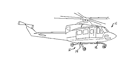
FIGURE 1 illu~rates the gui~k change wheel landlng
gaar ass~mbly of the pxe5ent inven~ion lnstalled on a
hellcopter;
FIGURE 2 ls a p~rspectlve v~ew of the qulck change
wheel l~ndlng gear assembly removed from the hellcopt~r;
and
FIGURE 3 is ~ perspectlve view of ~ portlon of the
present ~nventlon showing the elastomerlc bearlng ~nd
support assembly for the ~ft mai~ landlng gear.

~3~
DESCRIPTION OF THE PREFERRED ~MBODIME~TS
Referring to FIGURE 1, quick change tricycle
landing gear assembly lO ls shown mounted on a
hellcopter llo Landing gear assembly 10 ls designed to
replace a skid landlng gear ~sse~bly by mountlng
directly to the structural saddles 12 a~d 14 used to
mount the skld landlng ge~r assembly to the under~ide of
helicopter ll~
Referring to FIGURE 2, landlng gear ass~mbly lO 1~
shown removed from hellcopter 11. Landing gear assembly
10 comprises a pair of spaced-apart for~ and aft tubes
16 and 18 that extend gener~lly parallel to each other
and the longitudlnal axis of hellcoptex 11~ Fore and
aft tubes 16 ~nd 18 ~re attached to a palr o~ short,
spaced-apart ~ross tubes 20 and 22. Fore ~nd aft tubes
16 and 18 and cross tubes 20 and 22 are rigldly
connected by means of standard flttinys that are well
known in the art~ At the forward end of landing gear
assembly 10, fore and aft tubes 16 and 18 converge
downward ~ogether ~nd are rigldly connected to ~ plvot
bearlng assembly 24 having a generally vertical axls for
nose gear 26 to swlvel about. Nose gear 2S may be
mounted on a tralling arm connected to ~ sprlng assembly
~5 mounted for rotatlon about the axl~ of plvot bearing
2~ 24. Sprlng assembly 25 ~bsorbs vibrations and small
defleetions of nose gear 26 during taxllng to reduce
fatigue loads in ~he fore ~nd aft tubes 16 and 18. In
additlon, nose gear 26 may comprise dual nose wheels to
reduce shimmy of nose gear 26.
The aft portion of landing gear assembly 10
comprlses main gear wheels 30 and 32 mounted on
cantilever landlng gear legs 34 and 36. Ma1n gear legs
34 and 36 are mounted on for and aft tubes 1~ and 13,
respectlvely, so as to extend laterally therefrom
3s ad~acent the aft cross tube 22. Landlng loads on the

7 ~3~ ~
maln gear wheels 30 and 32 may be absorbed hy deflectlon
of th~ gear legs 34 and 36, reslllence of sprlngs
connecting the gear l~gs 34 and ~6 to the longltudlnal
tubes 16 and 18, de~lectlon of the aft cross tube 22,
torsion of the fore and aft 1OQg1tUd1na1 tube~ 16 and
18, or ~ny comblnatlo~ of these actlonsO
Referring to FIGURE 3, ~ connectlon brackPt 38 ls
shown conne~tlng fore and aft tube 18 to aft cross tub~
22. ~n elastomerlc bearing 40 1~ mounted on tube 1~ aft
of cross tube 22 and bracket 38. ~ cylindrlcal
elastomeric spring 42 may be bonded to the lnslde
surface of bearing 40 and to the outslde surface of
longitudlnal tube 18 inserted into bearlng 40. Bearing
40 may include a palr of lugs 46 for mounting ~ft gear
leg 3~ thereto. Longitudinal tube 16 includes a similar
connection bracket ~nd an elastomeric bearing wlth lugs
for mounting aft gear leg 34 thereto.
Landing gear assembly 10, as shown ln ~I~URES 1 and
2, ,s designed as a sIuick charlge replacement f or a skid
landlng gear system on helicopter 11. The cross tubes
~o and 22 of ge~r assembly 10 are adapted to attach to
the same structural saddles 12 and 14 used for attachiny
the skld landlng gear to the underside of hel~copter 11.
Alternatlvely, landlng gear assembly 10 may lnclude fore
and aft longi~udinal tubes 16 and 18 belng connected at
the aft end to the bac~ end fittings on the main
helicopter baan ln which c~se, a ~ull length aft cross
tube is ~sed and ls ~tabl~lzed wlth drag braces from the
ends of fore and aft tubes 16 ~nd 18.
Landing gear assembly 10 is a low co~t syst~ that
incorporates many of the maintenance free features of a
skid landing gear system. The only additional sccessory
that may be required is a~ hydraulic brake system for
the main gear wheels. ~ecausa landing gear assembly 10
3~ provides a quick means for back-flttlng exlstlny skid

~o~
g~ar helicopters wlth ~ wheel landlng gear system
wlthout requlring ma~or costly and heavy addltlonal
mountlng structures, l~dlng ge~r assembly 10 ellmln~tes
the previous ~eight and cost penalties lncurred ~hen
provlding wheels ~or helicopters equlpped with skid
landlng systems.
Although the present lnventlon has b~en descrlbed
with respect to a specific embod~ment thereof, v~rlous
changes and modifications to the descrlbed embodlment
may be suggested to one skilled in the ~rt~ ThereforP,
it is lntended that the present in~ention encompass su~h
rhanges and modiflcations as fall wlthin the scope of
the appendad claims~

Representative Drawing
A single figure which represents the drawing illustrating the invention.
Administrative Status

2024-08-01:As part of the Next Generation Patents (NGP) transition, the Canadian Patents Database (CPD) now contains a more detailed Event History, which replicates the Event Log of our new back-office solution.

Please note that "Inactive:" events refers to events no longer in use in our new back-office solution.

For a clearer understanding of the status of the application/patent presented on this page, the site Disclaimer , as well as the definitions for Patent , Event History , Maintenance Fee  and Payment History  should be consulted.

Event History

Description Date
Inactive: IPC from MCD 2006-03-11
Time Limit for Reversal Expired 2000-11-17
Application Not Reinstated by Deadline 2000-11-17
Deemed Abandoned - Failure to Respond to Maintenance Fee Notice 1999-11-17
Inactive: Status info is complete as of Log entry date 1998-04-30
Inactive: Application prosecuted on TS as of Log entry date 1998-04-30
Request for Examination Requirements Determined Compliant 1996-08-07
All Requirements for Examination Determined Compliant 1996-08-07
Application Published (Open to Public Inspection) 1990-06-08

Abandonment History

Abandonment Date Reason Reinstatement Date
1999-11-17

Maintenance Fee

The last payment was received on 1998-07-09

Note : If the full payment has not been received on or before the date indicated, a further fee may be required which may be one of the following

  • the reinstatement fee;
  • the late payment fee; or
  • additional fee to reverse deemed expiry.

Patent fees are adjusted on the 1st of January every year. The amounts above are the current amounts if received by December 31 of the current year.
Please refer to the CIPO Patent Fees web page to see all current fee amounts.

Fee History

Fee Type Anniversary Year Due Date Paid Date
Request for examination - standard 1996-08-07
MF (application, 8th anniv.) - standard 08 1997-11-17 1997-11-03
MF (application, 9th anniv.) - standard 09 1998-11-17 1998-07-09
Owners on Record

Note: Records showing the ownership history in alphabetical order.

Current Owners on Record
BELL HELICOPTER TEXTRON INC.
Past Owners on Record
CHARLES EDWARD DAVIS
JAY ROBERT DUPPSTADT
Past Owners that do not appear in the "Owners on Record" listing will appear in other documentation within the application.
Documents

To view selected files, please enter reCAPTCHA code :


To view images, click a link in the Document Description column. To download the documents, select one or more checkboxes in the first column and then click the "Download Selected in PDF format (Zip Archive)" or the "Download Selected as Single PDF" button.

List of published and non-published patent-specific documents on the CPD .

If you have any difficulty accessing content, you can call the Client Service Centre at 1-866-997-1936 or send them an e-mail at CIPO Client Service Centre.


Document
Description 
Date
(yyyy-mm-dd) 
Number of pages   Size of Image (KB) 
Claims 1990-06-07 4 119
Drawings 1990-06-07 2 35
Abstract 1990-06-07 1 40
Representative Drawing 1990-06-07 1 8
Descriptions 1990-06-07 8 272
Courtesy - Abandonment Letter (Maintenance Fee) 1999-12-14 1 184
Fees 1996-10-20 1 74
Fees 1995-10-11 1 65
Fees 1994-10-13 1 56
Fees 1995-10-13 1 59
Fees 1992-10-15 1 41
Fees 1991-10-23 1 42