Sélection de la langue

Search

Sommaire du brevet 2003186 

Énoncé de désistement de responsabilité concernant l'information provenant de tiers

Une partie des informations de ce site Web a été fournie par des sources externes. Le gouvernement du Canada n'assume aucune responsabilité concernant la précision, l'actualité ou la fiabilité des informations fournies par les sources externes. Les utilisateurs qui désirent employer cette information devraient consulter directement la source des informations. Le contenu fourni par les sources externes n'est pas assujetti aux exigences sur les langues officielles, la protection des renseignements personnels et l'accessibilité.

Disponibilité de l'Abrégé et des Revendications

L'apparition de différences dans le texte et l'image des Revendications et de l'Abrégé dépend du moment auquel le document est publié. Les textes des Revendications et de l'Abrégé sont affichés :

  • lorsque la demande peut être examinée par le public;
  • lorsque le brevet est émis (délivrance).
(12) Demande de brevet: (11) CA 2003186
(54) Titre français: TRAIN D'ATTERRISSAGE A ROUES A MONTAGE RAPIDE
(54) Titre anglais: QUICK-CHANGE WHEEL LANDING GEAR
Statut: Réputée abandonnée et au-delà du délai pour le rétablissement - en attente de la réponse à l’avis de communication rejetée
Données bibliographiques
(51) Classification internationale des brevets (CIB):
  • B64C 25/00 (2006.01)
  • B64C 25/02 (2006.01)
(72) Inventeurs :
  • DAVIS, CHARLES EDWARD (Etats-Unis d'Amérique)
  • DUPPSTADT, JAY ROBERT (Etats-Unis d'Amérique)
(73) Titulaires :
  • BELL HELICOPTER TEXTRON INC.
(71) Demandeurs :
  • BELL HELICOPTER TEXTRON INC. (Etats-Unis d'Amérique)
(74) Agent: KIRBY EADES GALE BAKER
(74) Co-agent:
(45) Délivré:
(22) Date de dépôt: 1989-11-17
(41) Mise à la disponibilité du public: 1990-06-08
Requête d'examen: 1996-08-07
Licence disponible: S.O.
Cédé au domaine public: S.O.
(25) Langue des documents déposés: Anglais

Traité de coopération en matière de brevets (PCT): Non

(30) Données de priorité de la demande:
Numéro de la demande Pays / territoire Date
PCT/US88/04319 (Etats-Unis d'Amérique) 1988-12-08

Abrégés

Abrégé anglais


13
QUICK CHANGE WHEEL LANDING GEAR
ABSTRACT OF THE DISCLOSURE
A quick change wheel landing gear assembly (10) is
provided as a replacement for a skid landing gear system
on a vertical take-off and lending aircraft. The wheel
landing gear assembly (10) includes a pair of spaced-
apart fore and aft longitudinal tubes (16, 18) attached
to a pair of short, spaced-apart cross tubes (20, 22)
that are adapted to mount on the structural saddles (12,
14) used to mount the skid landing gear on the underside
of the aircraft. The longitudinal tubes (16, 18) are
connected together at the forward end for mounting a
fully swiveling nose gear (26) thereto. Aft main gear
wheels (30, 32) are mounted on cantilever landing gear
legs (34, 36) that extend laterally from the
longitudinal tubes (16, 18) adjacent the aft cross tube
(22). Landing loads on the landing gear may be absorbed
by resilient springs (25), deflection of the gear legs
(34, 36) and the aft cross tube (22), torsion of the
fore and aft longitudinal tubes (16, 18), or any
combination of these actions. Resilient springs (25)
are used in the landing gear assembly (10) to attenuate
fatigue stresses in conjunction with the deflection of
the longitudinal (16, 18) and cross tubes (20, 22) of
the gear assembly (10). The wheel landing gear assembly
(10) is designed to be mounted on existing aircraft
structural saddles and to retain many of the desirable
features of a said landing gear system, including low
cost and easy maintenance.

Revendications

Note : Les revendications sont présentées dans la langue officielle dans laquelle elles ont été soumises.


9
WE CLAIM:
1. A wheel landing gear assembly for a vertical
take-off and landing aircraft, comprising:
a cross tube adapted for mounting the gear assembly
on the underside of the aircraft;
a pair of fore and aft tubes attached to said cross
tube, said fore and aft tubes extending generally
parallel to the longitudinal axis of the aircraft when
the gear assembly is mounted on the aircraft;
a pivotable nose gear mounted at the forward ends
of said fore and aft tubes;
a cantilever main gear leg mounted to and extending
laterally outward from the aft end of each of said fore
and aft tubes; and
a main gear wheel mounted on the laterally
extending end of each of said main gear legs.
2. The landing gear assembly of Claim 1, wherein:
said fore and aft tubes converge together forward
of said cross tube and attach to a pivot bearing; and
a spring assembly connects said pivotable nose gear
to said pivot bearing.
3. The lending gear assembly of Claim 1, wherein
an elastomeric bearing connects each of said cantilever
main gear legs to its respective fore and aft tube
adjacent said cross tube.
4. The landing gear assembly of Claim 3, wherein
aircraft landing stresses are absorbed by deflection of
said main gear legs, resilience of said elastomeric
bearings, and torsion of said fore and aft tubes.

10
5. A quick change tricycle landing gear assembly
for a vertical take-off and landing aircraft,
comprising:
a pair of fore and aft tubes adapted for extending
generally parallel to a longitudinal axis of the
aircraft;
a forward cross tube and an aft cross tube attached
to said pair of fore and aft tubes, said cross tubes
adapted for mounting of the underside of the aircraft;
a pivotable nose gear attached to a forward end of
said fore and aft tubes;
a cantilever main gear leg mounted to and extending
laterally outward from each of said fore and aft tubes
adjacent said aft cross tube; and
a main gear wheel mounted on the laterally
extending end of each of said main gear legs.
6. The landing gear assembly of Claim 5, further
comprising an elastomeric bearing mounted between each
of said main gear legs and said fore and aft tubes.
7. The landing gear assembly of Claim 6, wherein
said fore and aft tubes converge together forward of
said forward cross tube and terminate at a pivot bearing
attached thereto for mounting said nose gear.
8. The landing gear assembly of Claim 7, wherein
said nose gear comprises dual wheels mounted on said
pivot bearing by means of a spring assembly.
9. The landing gear assembly of Claim 8, wherein
aircraft landing stresses are absorbed by resilience of
said nose and main wheels, resilience of said spring
assembly mounting said nose gear to said pivot bearing,
deflection of said fore and aft tubes and said cross

11
tubes, deflection of said main gear legs, resilience of
said elastomeric bearings, and torsion of said fore and
aft tubes.

12
10. A quick change tricycle landing gear assembly
adapted for replacing a skid landing gear system on a
helicopter, the assembly comprising:
a pair of fore and aft tubes adapted for extending
generally parallel to a longitudinal axis of the
helicopter;
a forward cross tube and an aft cross tube attached
to said pair of fore and aft tubes, said cross tubes
adapted for mounting on the skid gear structural saddles
on the underside of the helicopter;
said fore and aft tubes converging together
downward and forward of said forward cross tube and
terminating at a pivot bearing attached thereto;
a pivotable nose gear comprising dual wheels
mounted to said pivot bearing by means of a spring
assembly;
a cantilever main gear leg mounted to and extending
laterally outward from each of said fore and aft tubes
adjacent said aft cross tube;
an elastomeric bearing mounted between each of said
fore and aft tubes and said corresponding main gear leg;
and
a main gear wheel mounted on the laterally
extending end of each of said main gear legs.
11. The landing gear assembly of Claim 10, wherein
helicopter landing stresses on said landing gear
assembly are absorbed by said spring assembly and said
elastomeric bearings, deflection of said main gear legs,
and torsion of said fore and aft tubes.

Description

Note : Les descriptions sont présentées dans la langue officielle dans laquelle elles ont été soumises.

- 2~3~
QUI~ C~NGE W~EL LANDING ~R
~ECHNICAL FIELD
This lnvention rslates to alrr~raft landing gear
systems and, in partlcular, to a quick change wheel
landing gear assembly provided as ~n ~lternate system
for a helicopter havlng a skld la~ding gear ass0mbly~
.
.. . .

86
~ACXGROUND O~ THE INVENTION
In helicopters and other vertlcal take-off and
landing alrcraft, varlous surface engaging systems may
be used depending upon the operatlonal requirements for
landlng the alrcraft. For example, helicopter landing
gear systems may comprlse skids, skls, wheels, or
~loats. ~n those systems, the energy of the shock and
stress encountered ~y the landlng gear when lt engages
the surfaca may be absorbed by restlient springs,
bending rods, torsion bars, air-filled bodles, or
various comblnatlons of these shock absorbing devices.
In some hellcopter operatlonal envlronments, lt is
highly desirable to be able to selertlvely change the
helicopter landlng gear conflguration. In particular,
it is sometlmes necessary to modify a helicopter having
a skld landlng gear assembly by providlng landing gear
wheels to facilitate moving the aircraft on $he gr~und.
secause of the critlcal nature of weight added to
helicopters, wheel landing gear systems provlded as add-
ons to landing sklds are undeslrable. However, it is
deslrable to provide a wheel landlng gear system that
replaces landing skids quickly without requirlng any
special structural provlsions. Th~s, thera is a need
for an alternate wheel landlng gear assembly that
raplaces a hellcopter's 5kld landlng gear and may be
lnstalled quickly uslng the same structural saddles used
for the skid landing gear assembly.
,

3 2~0~8~
SUMM~RY 0~ T~E INVENTION
The present lnventlon comprlses a wheel landing
gear assembly deslgned as a qulck rhange replacement for
a skld l~ndlng gear assembly on a hellcopter. The wheel
S landing gear assembly attaches to the hellcopter ~t th~
same structural saddle used for th~ attaGhing skld
landing gear to the alrcraft. Therefore, the present
invention provides an alternate wheel landing gear
assembly for a hallcopter wlthout addlng speclal landing
gear support structure othsr than mlnor brace and brake
fittlngs. Furthermor~, the ~ulck change wheel landlng
gear assembly provldss a ready means for back-flttlng
existlng skld gear helicopters wlth ~ wheel landing gear
system. Thus, new helicopters can be bullt without
costly and heavy addltional structures for mountlng an
alternate landing gear system.
The present lnvention is designed to preserve many
desirable features of a skld la~ding gear syst~m,
including low cost and easy malntenance. A palr of fore
and aft longltudlnal tubes are attached to ~ palr of
short, spaced-apart cross tubes that are posltioned to
be mounted on the helicopter structural saddles used to
mount the skld landing g83r. The longitudinal tubes act
as energy absorb2rs for vertlcal loads durlng landing
2~ and ~lso act to stabillze the landing gear ln the
presence of wheel drag loads during fllght. The
longltudlnal tubes are connected together at the forward
end for mountlng ~ nose gear thereto. The nose gear is
mounted so as to be fully swlvellng and lt m~y comprlse
dual wheels to reduce shlmmy. The aft main gear ~heels
are mounted on cantilever landlng gear legs extending
laterally from the lon~itudinal tubes at posltlons near
the aft cross tube. An alternate con~iguratlon includes
shorter fore and aft tubes, not attached to the rear
cross tube, ~ut anch~red at the back end to flttings on

the maln hslicopter be~ms. ~ ~ull length a~t cross tube
ls used and is stablllzed wl th drag braces rom the ends
of the fore and aft tubes to near the rear wheels on the
cross tube,
During landlng, nose ~ear loads are absorbed by
bendlng de~lectlon of the fore and aft longitudlnal
tubes. In addltlon, ~ resill~n~ spring ln the nosæ gear
may bs used to absorb ~nergy in con~unct10n with the
deflectlon of the longltudlnal tubes. ~andlng loads on
tne aft main gear may be absorbed by resllient sprlngs,
bendlng deflection of the gear legs and the aft cross
tube, torslon of the fore and aft longitudlnal tubes, or
any combln~tioQ of these actlonsO Also, the aft maln
gear sprlngs may be replaced by two aft cross tubes or
one cross tube and a drag brace used as a ~omblned
bendlng tube and truss conflguration ln some operatlonal
applications of the landing gear system.
Regular landlng and taxilng load~ and vlbratlons
are absorbed by the sprlngs and the deflection of ~he
longitudinal and cross ~ubes of the landing gear. ~any
different types of springs may be used in th~ landing
gear assembly, as i5 well known ln the ~rt. ~owever,
reslllent sprlngs are used ln the present invention to
attenuate fatlgue stresses ln con~unctlon with the
deflectlon of the longitudinal and cro~s tubas o~ the
landing gear assembly.

s ~ L8~
BRIE~ DESCRIPTION OF THE DR~WINGS
For a more complete understandlng of the present
invention and ~or ~urther adYantages thereof, reference
ls made to the followlng Descrlption of tha Preferred
S Embodiment taken ln con~unctlon ~lth th~ ~ccompanying
Drawlngs, in whlch:
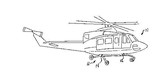
FIGURE 1 illu~rates the gui~k change wheel landlng
gaar ass~mbly of the pxe5ent inven~ion lnstalled on a
hellcopter;
FIGURE 2 ls a p~rspectlve v~ew of the qulck change
wheel l~ndlng gear assembly removed from the hellcopt~r;
and
FIGURE 3 is ~ perspectlve view of ~ portlon of the
present ~nventlon showing the elastomerlc bearlng ~nd
support assembly for the ~ft mai~ landlng gear.

~3~
DESCRIPTION OF THE PREFERRED ~MBODIME~TS
Referring to FIGURE 1, quick change tricycle
landing gear assembly lO ls shown mounted on a
hellcopter llo Landing gear assembly 10 ls designed to
replace a skid landlng gear ~sse~bly by mountlng
directly to the structural saddles 12 a~d 14 used to
mount the skld landlng ge~r assembly to the under~ide of
helicopter ll~
Referring to FIGURE 2, landlng gear ass~mbly lO 1~
shown removed from hellcopter 11. Landing gear assembly
10 comprises a pair of spaced-apart for~ and aft tubes
16 and 18 that extend gener~lly parallel to each other
and the longitudlnal axis of hellcoptex 11~ Fore and
aft tubes 16 ~nd 18 ~re attached to a palr o~ short,
spaced-apart ~ross tubes 20 and 22. Fore ~nd aft tubes
16 and 18 and cross tubes 20 and 22 are rigldly
connected by means of standard flttinys that are well
known in the art~ At the forward end of landing gear
assembly 10, fore and aft tubes 16 and 18 converge
downward ~ogether ~nd are rigldly connected to ~ plvot
bearlng assembly 24 having a generally vertical axls for
nose gear 26 to swlvel about. Nose gear 2S may be
mounted on a tralling arm connected to ~ sprlng assembly
~5 mounted for rotatlon about the axl~ of plvot bearing
2~ 24. Sprlng assembly 25 ~bsorbs vibrations and small
defleetions of nose gear 26 during taxllng to reduce
fatigue loads in ~he fore ~nd aft tubes 16 and 18. In
additlon, nose gear 26 may comprise dual nose wheels to
reduce shimmy of nose gear 26.
The aft portion of landing gear assembly 10
comprlses main gear wheels 30 and 32 mounted on
cantilever landlng gear legs 34 and 36. Ma1n gear legs
34 and 36 are mounted on for and aft tubes 1~ and 13,
respectlvely, so as to extend laterally therefrom
3s ad~acent the aft cross tube 22. Landlng loads on the

7 ~3~ ~
maln gear wheels 30 and 32 may be absorbed hy deflectlon
of th~ gear legs 34 and 36, reslllence of sprlngs
connecting the gear l~gs 34 and ~6 to the longltudlnal
tubes 16 and 18, de~lectlon of the aft cross tube 22,
torsion of the fore and aft 1OQg1tUd1na1 tube~ 16 and
18, or ~ny comblnatlo~ of these actlonsO
Referring to FIGURE 3, ~ connectlon brackPt 38 ls
shown conne~tlng fore and aft tube 18 to aft cross tub~
22. ~n elastomerlc bearing 40 1~ mounted on tube 1~ aft
of cross tube 22 and bracket 38. ~ cylindrlcal
elastomeric spring 42 may be bonded to the lnslde
surface of bearing 40 and to the outslde surface of
longitudlnal tube 18 inserted into bearlng 40. Bearing
40 may include a palr of lugs 46 for mounting ~ft gear
leg 3~ thereto. Longitudinal tube 16 includes a similar
connection bracket ~nd an elastomeric bearing wlth lugs
for mounting aft gear leg 34 thereto.
Landing gear assembly 10, as shown ln ~I~URES 1 and
2, ,s designed as a sIuick charlge replacement f or a skid
landlng gear system on helicopter 11. The cross tubes
~o and 22 of ge~r assembly 10 are adapted to attach to
the same structural saddles 12 and 14 used for attachiny
the skld landlng gear to the underside of hel~copter 11.
Alternatlvely, landlng gear assembly 10 may lnclude fore
and aft longi~udinal tubes 16 and 18 belng connected at
the aft end to the bac~ end fittings on the main
helicopter baan ln which c~se, a ~ull length aft cross
tube is ~sed and ls ~tabl~lzed wlth drag braces from the
ends of fore and aft tubes 16 ~nd 18.
Landing gear assembly 10 is a low co~t syst~ that
incorporates many of the maintenance free features of a
skid landing gear system. The only additional sccessory
that may be required is a~ hydraulic brake system for
the main gear wheels. ~ecausa landing gear assembly 10
3~ provides a quick means for back-flttlng exlstlny skid

~o~
g~ar helicopters wlth ~ wheel landlng gear system
wlthout requlring ma~or costly and heavy addltlonal
mountlng structures, l~dlng ge~r assembly 10 ellmln~tes
the previous ~eight and cost penalties lncurred ~hen
provlding wheels ~or helicopters equlpped with skid
landlng systems.
Although the present lnventlon has b~en descrlbed
with respect to a specific embod~ment thereof, v~rlous
changes and modifications to the descrlbed embodlment
may be suggested to one skilled in the ~rt~ ThereforP,
it is lntended that the present in~ention encompass su~h
rhanges and modiflcations as fall wlthin the scope of
the appendad claims~

Dessin représentatif
Une figure unique qui représente un dessin illustrant l'invention.
États administratifs

2024-08-01 : Dans le cadre de la transition vers les Brevets de nouvelle génération (BNG), la base de données sur les brevets canadiens (BDBC) contient désormais un Historique d'événement plus détaillé, qui reproduit le Journal des événements de notre nouvelle solution interne.

Veuillez noter que les événements débutant par « Inactive : » se réfèrent à des événements qui ne sont plus utilisés dans notre nouvelle solution interne.

Pour une meilleure compréhension de l'état de la demande ou brevet qui figure sur cette page, la rubrique Mise en garde , et les descriptions de Brevet , Historique d'événement , Taxes périodiques et Historique des paiements devraient être consultées.

Historique d'événement

Description Date
Inactive : CIB de MCD 2006-03-11
Le délai pour l'annulation est expiré 2000-11-17
Demande non rétablie avant l'échéance 2000-11-17
Réputée abandonnée - omission de répondre à un avis sur les taxes pour le maintien en état 1999-11-17
Inactive : Renseign. sur l'état - Complets dès date d'ent. journ. 1998-04-30
Inactive : Dem. traitée sur TS dès date d'ent. journal 1998-04-30
Exigences pour une requête d'examen - jugée conforme 1996-08-07
Toutes les exigences pour l'examen - jugée conforme 1996-08-07
Demande publiée (accessible au public) 1990-06-08

Historique d'abandonnement

Date d'abandonnement Raison Date de rétablissement
1999-11-17

Taxes périodiques

Le dernier paiement a été reçu le 1998-07-09

Avis : Si le paiement en totalité n'a pas été reçu au plus tard à la date indiquée, une taxe supplémentaire peut être imposée, soit une des taxes suivantes :

  • taxe de rétablissement ;
  • taxe pour paiement en souffrance ; ou
  • taxe additionnelle pour le renversement d'une péremption réputée.

Les taxes sur les brevets sont ajustées au 1er janvier de chaque année. Les montants ci-dessus sont les montants actuels s'ils sont reçus au plus tard le 31 décembre de l'année en cours.
Veuillez vous référer à la page web des taxes sur les brevets de l'OPIC pour voir tous les montants actuels des taxes.

Historique des taxes

Type de taxes Anniversaire Échéance Date payée
Requête d'examen - générale 1996-08-07
TM (demande, 8e anniv.) - générale 08 1997-11-17 1997-11-03
TM (demande, 9e anniv.) - générale 09 1998-11-17 1998-07-09
Titulaires au dossier

Les titulaires actuels et antérieures au dossier sont affichés en ordre alphabétique.

Titulaires actuels au dossier
BELL HELICOPTER TEXTRON INC.
Titulaires antérieures au dossier
CHARLES EDWARD DAVIS
JAY ROBERT DUPPSTADT
Les propriétaires antérieurs qui ne figurent pas dans la liste des « Propriétaires au dossier » apparaîtront dans d'autres documents au dossier.
Documents

Pour visionner les fichiers sélectionnés, entrer le code reCAPTCHA :


Pour visualiser une image, cliquer sur un lien dans la colonne description du document. Pour télécharger l'image (les images), cliquer l'une ou plusieurs cases à cocher dans la première colonne et ensuite cliquer sur le bouton "Télécharger sélection en format PDF (archive Zip)" ou le bouton "Télécharger sélection (en un fichier PDF fusionné)".

Liste des documents de brevet publiés et non publiés sur la BDBC .

Si vous avez des difficultés à accéder au contenu, veuillez communiquer avec le Centre de services à la clientèle au 1-866-997-1936, ou envoyer un courriel au Centre de service à la clientèle de l'OPIC.


Description du
Document 
Date
(aaaa-mm-jj) 
Nombre de pages   Taille de l'image (Ko) 
Revendications 1990-06-07 4 119
Dessins 1990-06-07 2 35
Abrégé 1990-06-07 1 40
Dessins représentatifs 1990-06-07 1 8
Description 1990-06-07 8 272
Courtoisie - Lettre d'abandon (taxe de maintien en état) 1999-12-14 1 184
Taxes 1996-10-20 1 74
Taxes 1995-10-11 1 65
Taxes 1994-10-13 1 56
Taxes 1995-10-13 1 59
Taxes 1992-10-15 1 41
Taxes 1991-10-23 1 42