Note: Descriptions are shown in the official language in which they were submitted.
- 2003703
FACS IMILE APPARATUS
BACKGROUND OF THE INVENTION
Field of the Invention
This invention relates to a facsimile apparatus of
the type which uses a roll of recording paper wound on
a spool.
Description of the Prior Art
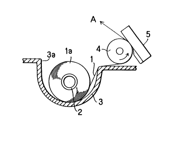
Figs. 1 and 2 illustrate in sectioned front and
side views a conventional facsimile apparatus as
disclosed in Japanese Laid-Open Utility Model
Application 60-25268, in which 1 is a thermosensitive
recording paper wound on a tubular spool 2 and forming
a roll portion la around the spool 2. 3 is a roll
holder tray having a recess 3a of substantially semi-
circular cross-sectional shape for nesting the roll
portion therein. The recording paper 1 is drawn out
from the lower side of the spool 2 and around a platen
roller 4. 5 is a thermal head which prints images by
contacting the recording paper 1 as it passes around
the platen roller 4.
Next, operation will be described. Normally the
recording paper 1 is set in position simply by placing
the roll portion la on the spool 2 in the recess 3a of
the roll holder tray 3. The recording paper is rolled
around the spool such that its printing face is
disposed on the outer side, and the recording paper is
drawn out from the lower side of the pool 2 and passed
2003703
around the platen roller 4 for pressure contact with
the thermal head 5. The paper which has undergone
thermal recording by the thermal head 5 is discharged
in the direction of arrow A.
Conventional facsimile apparatus arranged in the
above-described manner have a problem that, when the
diameter of the roll portion la of the recording paper
1 on the spool 2 become small as the paper is consumed,
it is likely that the roll is tilted by a pulling force
acting on the lower side of the roll portion la, as a
result destabilizing the transport of the recording
paper or causing the paper to advance obliquely and
enter the path between the platen roller 4 and the
thermal head 5 at an oblique angle. If recording is
effected on the paper in such a state, the roll portion
la tends to engage the side wall surfaces of the recess
3a, such that withdrawal of the paper under such
conditions causes damage to the recording paper.
Further, when the recording paper is replaced by a
roll of a different width, especially when replaced by
a roll of a smaller width, the oblique motion of the
paper is more likely to occur, necessitating the
provision of guide members respectively for paper rolls
of different widths.
SUMMARY OF THE INVENTION
It is an object of the present invention to
provide a facsimile apparatus which can feed recording
paper from a roll stably and without oblique motions
irrespective of the rolled paper diameter to prevent
paper damage which would result from unstable paper
motion.
It is another object of the present invention to
provide a facsimile apparatus which can feed recording
_ _ 3 2003703
paper from a roll securely without oblique motion
irrespective of the width of the rolled paper.
It is still another object of the invention to
provide a facsimile apparatus which can feed recording
paper in a secure and stable manner by simple and
inexpensive means, without resorting to any expensive
device.
In accordance with one aspect of the invention
there is provided a facsimile apparatus, comprising:
a recording paper roll holder box for holding a roll of
recording paper of various widths, on which images are
recorded by a recording head; first and second flange
members each having an inwardly extending, integrally
formed shaft portion detachably engaged in a respective
end of said roll so as to contact said respective end
in a snug fitting manner, and an outwardly extending,
integrally formed shaft portion, wherein said inwardly
and outwardly extending, integrally formed shaft
portions constitute permanently fixed, unremovable
parts of said first and second flange members; said
roll holder box including engaging means for engaging
said outwardly extending shaft portions such that said
recording paper of various widths is drawn from said
roll in a stable manner free from undesirable motion.
In accordance with yet another aspect of the
invention there is provided a facsimile apparatus,
comprising: a recording holder roll box for holding a
roll of recording paper of various widths on which
images are recorded by a recording head; first and
second flange members each having a permanently fixed,
unremovable axially extending short portion and a
permanently fixed, unremovable axially extending long
portion on opposing sides thereof, said axially
extending long portions having radially retractable
projections thereon, said short portions being
detachably engageable in respective ends of a roll of
relatively small width and said long portions being
....
4 2003703
detachably engageable in respective ends of a roll of
relatively large width, by reversing the orientation of
said flange members with respect to said rolls; said
roll holder box including engaging means for engaging
said axially extending short portions when a roll of
relatively large width recording paper is used in said
apparatus, and for engaging and rotatably supporting
said axially extending long portions when a roll of
relatively small width recording paper is used in said
apparatus, wherein said radially retractable
projections project from said axially extending long
portions when said roll of relatively small width is
used, to prevent said roll of relatively small width
from moving in an axial direction within said roll
holder box by contacting inner surface of said roll
holder box adjacent said engaging means, and wherein
said radially retractable projections are retracted
into said axially extending long portions when said
roll of relatively large width is used in said
apparatus.
The facsimile apparatus according to a preferred
embodiment of the invention is capable of transporting
the recording paper continuously in a stable state free
of oblique motion even when the rolled paper portion on
the spool is reduced to a small diameter.
Further, the facsimile apparatus according to a
preferred embodiment of the invention is capable of
feeding the recording paper continuously in a secure
posture free of undesirable deviational or oblique
motion even when the paper roll has a small width.
The above and further objects and novel features
of the invention will more fully appear from the
following detailed description given in connection with
the accompanying drawings. It is to be expressly
understood, however, that the drawings are for purposes
of illustration only and are not intended to limit the
invention.
~ 4a
2003703
BRIEF DESCRIPTION OF THE DRAWINGS
Fig. 1 is a sectional front view of a conventional
facsimile apparatus;
Fig. 2 is a sectional side view of the
conventional facsimile apparatus of Fig. 1;
Fig. 3 is a sectional front view of a facsimile
apparatus according to one embodiment of the present
invention;
Fig. 4 is a fragmentary side view of the apparatus
of Fig. 3;
Fig. 5 is a partly sectional front view of a
flange member of another embodiment of the invention;
Fig. 6 is a sectional front view of a facsimile
apparatus according to another embodiment of the
invention; and
Fig. 7 is a perspective view of the flange 6 shown
in Fig. 3.
DETAILED DESCRIPTION OF THE PREFERRED EMBODIMENTS
The preferred embodiments of the invention will be
described in detail with reference to the accompanying
drawlngs.
Z003703
s
Figs. 3 and 4 show a facsimile apparatus embodying
the present invention in a sectional front view and a
fragmentary side view, respectively, in which the
component parts common to those in Figs. 1 and 2 are
designated by common reference numerals, their
description being omitted to avoid unnecessary
repetition.
Indicated at 6 are flanges which are press-fitted
into the opposite ends of a tubular spool 2, which have
an outer diameter slightly larger than the m-ximum
diameter of a roll portion la, and which engage and
hold the opposite ends of the roll portion la on the
spool 2.
Each flange 6 is integrally provided with a
cylindrical shaft-like portion 6a adapted to be press-
fitted into the spool 2 as shown in Fig. 3.
This fit-in shaft portion 6a has an outer diameter
slightly larger than the inner diameter of the bore of
spool 2, and is press-fitted into the bore of spool 2
in cooperation with four axial slits as shown in Fig. 7
which are formed axially from the outer end of the
shaft portion 6a to impart thereto resiliency in the
radial direction. Further, the flange 6 is centrally `
provided with an axially outwardly extending shaft
portion 6d opposite to the shaft portion 6a.
U-shaped guide grooves 3b are formed in the
opposite side walls of roll holder tray 3 to engage
shaft portions 6d.~
The disk-shaped portion of the flange 6 preferably
has an outer radius which is slightly larger than the
distance between the inner bottom surface of the roll
holder tray 3 and the bottom surface of the guide
groove 3b, and is thus in abutting engagement with the
inner bottom surface of the roll holder tray 3 at the
X003703
-
outer peripheral edge of the flange 6. As shown most
clearly in Fig. 4, there is a clearance between the
bottom surface of the guide groove and the shaft
portion 6d.
Next, the operation will be described. The
recording paper 1 is drawn out from the lower side of
the roll portion la, so that the diameter of the roll
portion la is gradually reduced and finally becomes
almost as small as the outer diameter of the spool. At
such point, the gap space between the roll portion la
and the inner surface of the recess 3a becomes far
larger than a gap space formed by a roll of a large
diameter. However, since the flanges 6 holding the
opposite ends of the roll portion la maintain a
constant gap between the flanges 6 and the inner
surfaces of the recess 3a irrespective of the roll
diameter, the flanges 6 and roll la are retained in
substantially the same regular motion in the recess 3a
without being influenced by the roll diameter.
Therefore, the recording paper 1 is fed out stably and
prevented from advancing obliquely between the platen
roller 4 and the thermal head 5.
Further, irregular motions of the recording paper
1 are eliminated as the shaft portions 6d of the
flanges 6 are held in the guide grooves 3b. In
addition, the abutting engagement of the outer
peripheral edges of the disk-like portions of the
flanges 6 with the inner bottom surfaces of the roll
holder tray 3 generates frictional forces, which
contribute to stable travel of the recording paper by
applying a certain tension thereto to prevent
slackening of the recording paper 1 which would
otherwise be caused by over-rotation of the roll
portion la. The shaft portions 6d have a length
Z003~0;~
sufficient to accommodate different widths of recording
paper.
Figs. 5 and 6 show another embodiment of the
invention by way of a sectional side view of the flange
and a sectional front view of the facsimile apparatus,
respectively. In these figures, the component parts
common to Figs. 3 and 4 are designated by common
reference numerals and their descriptions are omitted
to avoid repetition.
In these figures, indicated at 10 is a recording
thermo-sensitive paper of a small width, 20 is a
tubular spool carrying a roll of the recording paper
10, lOa is a roll portion of the recording paper 10,
and 60 are flanges fitted in the opposite end portions
of the tubular spool 20. Each flange 60 is integrally
provided with an axially extending cylindrical short
shaft portion 60d and a long shaft portion 60a
centrally on the opposite sides of its disk-like body.
The long shaft portion 60a is provided with fitting
holes 60e (seen move clearly in Fig. 5) in a position
to secure the roll of narrow width recording paper
within the roll holder tray 3. Stopper projections 61
are retractably fitted in the apertures 6Oe by the use
of resilient urging means such as springs 62. The
short shaft portion 60d has another diameter which is
slightly larger than the inner diameter of the spool
20, and press-fitted in the spool 20 in cooperation
with four axial slits as shown in Fig. 7 which are
formed axially from the outer end of the short shaft
portion 60d to impart thereto resiliency in the radial
direction. Although the longer shaft portion 6Oa has
an outer diameter slightly smaller than the spool 2
carrying a paper roll of large width, it can be fi`tted
into the spool 2 with similar press-fit effect by the
2~)03~0~
-
pressing forces of the retractable stopper projections
61 against the inner periphery of the spool 2.
Next, operation will be described. When using a
roll of recording paper 10 with a smaller width, the
short shaft portions 60d of the flanges 60 are press-
fitted into the opposite ends of the spool 20. Thus,
the flanges 60 become rotatable integrally with the
roll of recording paper 10. The long shaft portions
60a which extend outwardly from the respective flanges
60 at the opposite ends are then engaged in the
U-shaped guide grooves 3a of the holder box 3. In this
position, the retractable projections 61 on the long
shaft portions 60a act as stoppers for restricting
undesirable lateral movements of the recording paper
10. Therefore, the recording paper 10 is invariably
fed in centralized state. On the other hand, when
using a roll of recording paper having a larger width,
the long shaft portions 60a are press-fitted into the
spool 20 with retractable projections 61 providing a
holding force for the spool.
As described hereinbefore, according to the
present invention, the spool which carries a roll of
recording paper is provided with flanges at the
opposite ends thereof, the flanges each having an
outwardly extending shaft portion which is engageable
with a guide groove of a recording paper holder box to
restrict undesirable movements of the rolled recording
paper.
This arrangement is effective for feeding the
recording paper constantly in a stable state without
being influenced by the diameter of the rolled
recording paper and free of damage.
Furthermore, according to another aspect of the
invention, the flanges are provided with a short shaft
-
- Z003703
portion and a long shaft portion centrally on the
opposite side thereof, and retractable stopper
projections fitted in the long shaft portion in a
position to maintain narrow width recording paper roll
stably within the roll holder box, thereby restricting
unnecessary or undesirable movements in the lateral
direction of the recording paper to realize stable and
secure travel of the recording paper irrespective of
its width.