Note: Descriptions are shown in the official language in which they were submitted.
Z003951.
BACKGROUND OF THE lNV~hllON
A vehicular exhaust system comprises one or more
pipes for carrying exhaust gases from the engine. Each pipe
extending from the engine may lead to a catalytic converter
which is operative to convert certain ob~ectionable gases
in the exhaust stream into less objectionable forms. An exhaust
pipe extends from the catalytic converter to a muffler which
is operative to attenuate the noise associated with flow of
- exhaust gases. A tail pipe then extends from the muffler
to a location on the vehicle where the exhaust gases can be
safely and conveniently released.
The typical prior art exhaust muffler comprises
a plurality of separate tubes supported in a parallel array
by a plurality of transversely extending baffles. Selected
portions of each tube may comprise perforations, louvers or
apertures to permit exhaust gases traveling therethrough to
escape in a controlled manner. Each tube typically is securely
connected to at least one baffle and the array of assembled
parallel tubes and transverse baffles are then slid into a
generally tubular shell having a circular or oval
cross-sectional configuration which corresponds to the shape
of the baffles. A separate outer wrapper typically is wrapped
around the outer shell to dampen noise associated with the
vibration of the shell. A pair of opposed end caps or headers
are then securely connected to the opposed longitudinal ends
of the tubular shell and outer wrapper to substantially enclose
the muffler. Each end cap typically comprises at least one
- aperture to permit communication with the internal portions
of the muffler. The apertures in the end caps typically are
aligned to mate with one of the tubes within ,the muffler.
The assembly of components in this typical prior art muffler
defines a plurality of chambers. In particular, chambers
-- 2
Z0039~ -
are defined between the tubular shell and either a pair of
spaced apart baffles or between one baffle and one end cap
of the prior art muffler. The relative spacing of the baffles
in the muffler, the dimensions of the tubes therein and the
dimensions of the perforations, louvers, apertures or the
like are all selected to enable a specified attenuation of
exhaust gas noise. More particularly, the exhaust gas flowing
through the system expands through the various perforations,
louvers, apertures or the like and into the corresponding
chambers to achieve the specified noise attenuation.
When the above described exhaust muffler is intended
for an original equipment installation, the muffler typically
is welded to the elongated circuitous exhaust pipe and tail
pipe. The assembly of the muffler, the exhaust pipe and the
tail pipe is then delivered to the original equipment vehicle
manufacturer, such that the complete exhaust system assembly
can be mounted to the vehicle.
The prior art mufflers and exhaust system components
described above generally have provided adequate attenuation
of noise associated with the flow of exhaust gas. However,
the prior art exhaust muffler has required a large number
of separate components which had to be assembled in a labor
intensive manufacturing process. The resulting muffler tended
to be unnecessarily heavy and offered few design options per-
taining to the shape of the muffler or the alignment of pipes
leading to or away from the muffler. These inherent limitations
with the above described prior art mufflers have made it
extremely difficult to fit the exhaust system into the.limited
available space on the underside of the vehicle.
The prior art further includes mufflers whlch comprise
stamp formed components. For example, U.S. Patent No. 4,396,090
which issued to Wolfhugel on August 2, 1983 shows a muffler
- Z003951
having a pair of internal plates stamp formed to define pairs
of opposed channels. The internal plates are assembled such
that the channels are in register with one another and define
tubes therebetween. The internal plates are then disposed
within the above described conventional wrapped outer shell
to define a muffler. Separate internal baffles extend between
the stamped plates and the wrapped outer shell to define cham-
bers within the muffler of U.S. Patent No. 4,396,090.
The prior art also includes mufflers consisting
of only two opposed shells which are stamped to define a convo-
luted array of stamp formed tubes and stamp formed chambers.Mufflers of this type are shown in: U.S. Patent No. 2,484,827
which issued to Harley on October 18, 1949; U.S. Patent No
3,176,791 which issued to Betts et al. on April 6, 1965 and
U.S. Patent No. 3,638,756 which issued to Thiele on February
1, 1972.
The prior art further includes mufflers that are
formed from four stamped components. Mufflers of this type
comprise a pair of internal plates that are stamped to define
opposed channels. The plates are secured in face-to-face
rèlationship with one another such that tubes are defined
by the opposed channels. The internal plates are further
provided with stamp formed perforations, louvers or the llke
to permit expansion of the exhaust gas from the formed tubes.
These mufflers further comprise a pair of stamp formed external
shells which define a chamber surrounding and enclosing the
internal plates. The chambers define a single enclosed volume
into which the exhaust gases may expand. Prior art mufflers
of this general type are shown in: British Patent No. 632,013
30 which issued to White in 1949; British Patent ,No. 1,012,463
which issued to Woolgar on December 8, 1965; and U.S. Patent
No. 4,132,286 which issued to Hasui et al. on January 2, 1979.
- 4 -
2003~35~.
Certain prior art mufflers have been formed from
three or more stamped components plus a plurality Or tubular
components. For example, the above cited U.S. Patent No.
4,132,286 to Hasui shows a muffler having a perforated internal
plate which is stamped to define at least one channel.
Conventional tubular members conforming to the shape Or the
channels in the perforated plate are supported by and retained
in the channels. The muffler of U.S. Patent No. 4,132,286
further comprises a pair of opposed stamp formed external
shells effectively defining a clam shell to surround the perfo-
rated internal plate and the tubes supported therein. The
muffler shown in U.S. Patent No. 4,132,286 effectively defines
only a single internal chamber into which exhaust gases expand.
The acoustical tuning capabilities of a muffler of this general
type are very limited, and it would be extremely difficult
for a muffler as shown in U.S. Patent No. 4,132,286 to achieve
the noise attenuation requirements of mufflers for most vehicles
manufactured or sold in the United States.
A muffler similar to the muffler shown in the above
cited U.S. Patent No. 4,132,286 is shown in British Patent
No. 2,120,318 which issued to Allday on November 30, 1983.
In particular, British Patent No. 2,120,318 shows a muffler
havlng a plurality of tubes supported in a parallel array
by a plurality of tranversely extending baffles. The array
of tubes and the baffles are disposed in opposed stamp formed
external shells of generally clam shell configuration. However,
the external shells shown in British Patent No. 2,120,318
are part of extremely complex stampings which further define
both a stamp formed exhaust pipe and a stamp formed tail pipe.
The stamped external clam shells and the stamped exhaust plpe
and tail pipe unitary therewith would require extremely expen-
sive dies. Furthermore, the internal components required
Z003951.
by Brltish Patent No. 2,120,318 lnherently require the comblna-
tion of tubes and separate baffles which must be assembled
in the labor intensive manufacturing processes described with
respect to the traditional prior art mufrler.
Still another prior art muffler incorporating both
tubular and stamped components is shown in published Japanese
Patent Application No. 59-43456. Unlike the two previously
described references, the muffler shown in Japanese Application
No. 59-43456 includes at least four stamped components in
- 10 combination with tubular members. In particular, the muffler
shown in Japanese Patent Application No. 59-43456 includes
a pair of stamped internal plates with formed channels that
define tubes when the internal plates are disposed in face-to-
face relationship. Additionally, portions of each internal
plate are folded generally orthogonal to the remainder of
the plates to define a wall extending transverse to the stamp
formed tubes. Separate stamp formed baffles also are provided.
The muffler shown in published Japanese Patent Application
No. 59-43456 further comprises a pair of stamp formed exterior
clam shells which surround the internal plates. The external
-~ clam shells and the folded portions of the internal plate
define complementary configurations, such that the folded
portions of the internal plates define bafrles within the
muffler. The muffler further includes tubular members which
extend between the external shell and the baffles formed by
the folded portions of the internal plates. The muffler shown
in Japanese Patent Application No. 59-43456 is extremely com-
plex, expensive and could be difficult to assemble. In particu-
lar, this muffler includes at least four stamped components
with corresponding dedicated dies plus a pair of separate
tubular members. It is believed that the stamped internal
plates would have to be assembled and welded to one another.
-- 6 --
200395~
- The separate tubular members would then have to be securely
connected to the stamped internal plates by welding or the
like. The separate baffles would also have to be securely
connected to the stamped internal plates. The opposed exterior
,,~ clam shells ~ould then have to be securely assembled around
the subassembly consisting of the opposed stamped internal
plates, the separate baffles and the separate tubes.
The above described prior art stamp formed mufflers
provide certain advantages over the conventional mufflers
with wrapped outer shells. In particular, many of the above
described stamp formed mufflers would be lighter than conven-
tional mufflers and could -be manufactured in processes that
are well suited to automation. However, most of the above
described prior art stamp formed mufflers generally did not
provide a level Or acoustical tuning that would be acceptable
on vehicles manufactured or sold in the United States. As
a result, until recently, stamp formed mufflers did not achieve
significant commercial success in the United States.
Recently there have been several substantial advances
in the stamp formed muffler art. In particular, U.S. Patent
No. 4,700,806 which issued to Jon Harwood on October 20, 1987
shows a muffler formed from stamp formed components and provid-
ing the combination of at least one tuning tube and at least
one low frequency resonating chamber. One embodiment of the
mufflers shown in U.S. Patent No. 4,700,806 shows a pair of
internal plates formed to define channels therein. The plates
are secured to one another such that arrays of tubes are defined
by the channels. Selected portions of the channels are provided
with perforations or other such aperture means for permitting
a controlled expansion of the exhaust gases flowing through
the formed tubes. The mùffler of U.S. Patent No. 4,700,806
further comprises a pair of external shells. In the above
20039~1
.
referenced embodiment, the external sllells comprise a peripheral
portlon and a crease connectlng spaced apart locations on
the perlpheral portlons. The crease ls rormed to be ln contact
wlth the lnternal plate substantlally continuously between
the peripheral portions of the external shell. Thus, the
crease shown in U.S. Patent No. 4,700,806 effectively derlnes
a bafrle which enables a plurality of chambers to be defined
by the external shell. The locatlon of the crease shown in
U.S. Patent No. 4,700,806 is selected ln accordance with the
volume Or the chambers requlred for the specified nolse attenua-
tlon and exhaust gas flow characteristics.
Other improvements relating to stamp formed murflers
are shown in U.S. Patent No. 11,736,817 which issued to Jon
Harwood on April 12, 1988; U.S. Patent No. 4,759,423 which
issued to Jon l~arwood et al. on July 26, 1988; U . S . Patent
No. 4,760,89ll which issued to Jon ~larwood et al. on August
2, 1988; and, U.S. Patent No. 4,765,437 which issued to Jon
Harwood et al. on August 23, 1988. All of the above describedHarwood patents are assigned to the assignee Or the sub~ect
invention.
Mufflers manufactured in accordance with the above
descrlbed Harwood patents have achieved considerable commercial
success in a very short time. All of this commercial success
relates to original equipment murrlers where the nu~ber Or
murflers Or a particular type have been sufficient to readily
orfset the costs associated with the stamping dies. It ls
anticlpated, however, that there may be some situatlons where
the volume Or mufrlers may be small, thereby increasing the
per muffler costs associated with the four ,stamping dies
- required ror four stamp formed components Or a muffler. It
is also anticipated that in some situations the exhaust gas
y~ .
~ Z003951
~~flow wlll requlre fairly uncompllcated acoustlcal tuning.
For these situations, lt is desired to provide a muffler that
can be manufactured with very low initial manufacturing costs
and low material costs, while still providing the very desirable
advantages of a manufacturing process that is well suited
to automation. Furthermore, it is well known that weight
reductions can improve fuel efficiency and other aspects of
engine performance. Therefore, it is desirable to provide
lower weight vehicular components whenever possible.
Accordingly, it is an ob~ect of the subject invention
to provide an exhaust muffler having a substantially minimal
number Or components.
It is another ob~ect of the sub~ect invention to
provide a very light weight muffler and exhaust system.
An additional object of the sub~ect invention is
to provide a muffler with stamp formed components but with
low die costs.
Still a further object of the subject invention
is to provide a muffler which facilitates automated welding
of the muffler components.
Another ob~ect of the sub~ect invention is to provide
a muffler with baffles of integral construction and unitary
with the external shell for supporting tubular components
of the muffler.
~s~
~003951
SUMMARY OF THE lNV~N~l~lON
The sub~ect invention is directed to an exhaust
muffler comprising a pair of opposed external shells each
of which is formed to define a plurality of chambers. The
external shells may be formed by stamping or other known metal
forming techniques. Each external shell is formed to define
a peripheral portion which may be a peripheral flange. The
peripheral portion may be disposed to lie generally in a single
plane. The peripheral portions of the two formed external
shells may be dimensioned to be placed generally in register
with one another to enable the opposed peripheral portions
to be securely connected to one another.
The external shells further are formed to define
at least one baffle crease extending between and connecting
a pair of spaced apart peripheral portions of the external
shell. The base of the baffle creases include a plurality
of non-linear portions at least some of which may be dimensioned
to surround and closely engage tubes within the muffler, as
explained herein. The creases in the external shells may
be disposed to be placed generally in register with one another
such that portions of the base Or a baffle crease in one exter-
nal shell are in face-to-face contact with corresponding por-
tions of the base of a bafrle crease ln the other external
shell. Each external shell may comprise a plurality of baffle
creases, with each crease in one external shell being generally
in register with a corresponding crease in the other external
shell. Portions of the base of each such baffle crease in
one external shell may be in contact with corresponding portions
of the base of the respective baffle creases in the other
external shell. The non-linear portions of the paffle creases
may be any configuration but preferably may be substantially
semi-circular or semi-cylindrical and may be dimensioned to
- 10 -
-
200;~951
closely engage a substantially cylindrical tube. Selected
nonlinear portions of the baffle creases may be dimensioned
to provide controlled communication between chambers. In
par~ticular, non-linear portions of the baffle creases may
define stamp formed tubes.
Portions of the external shells may further be formed
to engage at least one inlet pipe to the mufrler and at least
one outlet pipe from the muffler. The portions of the external
shells for engaging the inlet and outlet pipes may be substan-
tially adjacent peripheral portions Or each external shelland may be substantially semi-circular or semi-cylindrical
or other suitable configuration to conform to the shape of
the pipes.
Remaining portions of the external shells may define
a shape which is selected to conform to the available space
on a vehicle. At least one of the external shells may include
a concave conformal area which is shaped to conform to a convex
structure on the vehicle. The external shells may be mirror
images of one another to enable a pair of mateable external
shells to be formed from a single set of stamping dies.
The muffler further comprises an array Or tubes
disposed at least partly within the muffler. The tubes ln
the array are supported within the external shell by the non-
linear portions of the baffle creases formed in the external
shell. At least selected tubes may further be supported by
the inlet and outlet portions of the external shell. Selected
portions of each tube may be provided with arrays of perfora-
tions, louvers, apertures or the like to permit a controlled
flow and/or expansion of exhaust gases therefrom and into
an expanslon chamber defined in part by baff~e creases Or
the external shells. At least one tube within the muffler
may define a tuning tube which is disposed to communicate
.
.
`-- 20~39~.
with an enclosed low frequency resonating chamber defined
in part by the baffle creases of the external shells. At
least one tube may extend externally from the muffler to define
a continuous unitary exhaust pipe or tail pipe. Portions
of the continuous unitary exhaust pipe and/or tail pipe disposed
within the muffler may comprise the above described perfora-
tions, louvers, apertures or other means to permit a flow
of exhaust gas therefrom. Portions of the continuous exhaust
pipes or tail pipes disposed within the muffler and/or portions
thereof disposed external to the muffler may be non-linear.
The external shells are securely engaged to one
another and around the tubes of the muffler. The external
shells preferably are secured directly to one another at least
at selected locations along portions of the baffle creases
which are in face-to-face contact with one another. Thus,
opposed baffle crèases will structurally and functionally
define an integral baffle, but will further be unitary with
the respective external shells. The secure connection of
the external shells to one another may be by welding or by
an appropriate mechanical connection means.
A preferred manufacturing and assembly method includes
the formation of the inlet and outlet portions of external
shells to be aligned with selected non-linear portions of
the baffle creases. The external shells are then connected
to one another by welding or appropriate mechanical interconnec-
tion means. The tubes having apertures, louvers or the like
formed therein are then inserted into the inlet or outlet
openings a sufficient distance to pass through and be supported
by the non-linear portion of the baffle crease aligned there-
with. The tubes may then be welded to peripheral portionsof the external shells.
- 12 -
2003951
In one broad aspect, the present invention relates to
a light weight exhaust muffler comprising: a pair of generally
tubular pipes having perforation means extending therethrough
for enabling the flow of exhaust gases therefrom, said pipes
defining an inlet and an outlet respectively for the muffler;
and a pair of formed external shells, each said external shell
comprising a peripheral portion, with the peripheral portions
of said external shells being securely connected to one
another, each said external shell further comprising a
_ ,5",,,. 10 plurality of chambers formed therein and extending from the
peripheral portions thereof, the chambers of each said external
shell being separated from one another by baffle creases
unitary with the respective external shells and extending
between and connecting spaced apart locations on the peripheral
portions of said external shells, the baffle creases of said
external shells being generally in register with one another
and including portions surrounding and engaging the pipes of
said muffler, and a non-linear portion formed in at least one
of the registered baffle creases and spaced from the baffle
crease in register therewith to define a formed tube extending
between the chambers of the muffler separated by the baffle
- crease.
In another broad aspect, the present invention
relates to a light weight exhaust muffler, comprising: a pair
of pipes of unitary construction having opposed ends, each said
pipe comprising aperture means extending therethrough at
locations spaced from said ends for permitting a flow of
exhaust gas therethrough, said pipes defining an inlet and an
outlet respectively for the muffler; and a pair of opposed
external shells securely connected to one another, each said
external shell being unitarily formed to define a peripheral
flange and a plurality of chambers extending from the
- 12(a) -
~_ 2003951
peripheral flange thereof, the chambers being separated from
one another by baffle creases formed unitarily in the
respective external shells and extending between and connecting
spaced apart locations on said peripheral flanges, the
respective baffle creases of the opposed external shells being
generally in register with one another, each said baffle crease
including planar portions in abutting face-to-face relationship
with the planar portions of the baffle crease in register
therewith, said baffle creases further comprising nonplanar
portions extending from the planar portions, selected nonplanar
portions being engaging and supporting the pipes of said
muffler, at least one nonplanar portion being spaced from the
pipes to define a formed tube for providing communication
between two of said chambers.
J 2003951.
BRIEF DESCRIPTION OF THE DRAWINGS
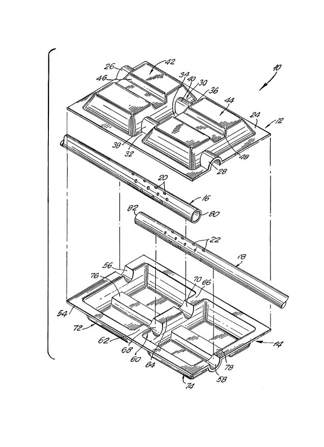
FIG. 1 is an exploded perspective view of a muffler
in accordance with the sub~ect application.
FIG. 2 is a side elevational view of the muffler
of FIG. 1 shown in its assembled form.
FIG. 3 is a cross-sectional view taken along line
3-3 in FIG. 2.
FIG. 4 is a cross-sectional view taken along line
4-4 in FIG. 2.
FIG. 5 is a cross-sectional view taken along line
5-5 in FIG. 3.
FIG. 6 is a side elevational view of a second embodi-
ment of a muffler in accordance with the sub~ect invention.
FIG. 7 is a cross-sectional view taken along line
7-7 in FIG. 6.
FIG. 8 is an end view of a third embodiment of a
muffler in accordance with the subject invention.
FIG. 9 is a cross-sectional view taken along line
9-9 in FIG. 8.
--13--
- ~: o~
2003951.
DETAILED DESCRIPTION OF TH~ PREFERRED EMBODIMENTS
A muffler in accordance with the sub~ect invention
is identified generally by the numeral 10 in FIGS. 1-5. The
muffler 10 comprises external shells 12 and 14 which are formed
from unitary sheets of metal such as aluminized steel, galva-
nized steel or stainless steel or from suitable nonmetallic
materials. The muffler 10 further comprises tubes 16 and
- 18 which are disposed at least partly within the muffler 10.
As depicted herein, the tubes 16 and 18 extend unitarily to
external locations relative to the muffler 10 and define at
least portions of an exhaust pipe and tail pipe respectively.
However, in certain embodiments, the tubes 16 and 18 will
terminate substantially ad~acent the periphery of the muffler
10, thereby defining an inlet and an outlet for the muffler.
At least one separate exhaust pipe and tail pipe will then
be connected to the inlet and outlet of the muffler. Portions
of the tubes 16 and 18 disposed within the muffler 10 are
provided with perforations 20 and 22 which are selectively
dimensioned and disposed to permit a controlled flow of exhaust
gases from the tubes 16 and 18, as explalned herein. It is
to be understood that in accordance with normal practice ln
the industry, the perforations 20 and 22 may be replaced by
other means for permitting the expansion of exhaust gases,
such as louvers, apertures or the like.
The external shells 12 and 14 are depicted as being
substantially mirror images of one another. As a result,
a single stamping die may be employed to form both the external
shell 12 and the external shell 14. The use of substantially
identical external shells 12 and 14 further simplifies inventory
control. In many embodiments, however, the mirr,or image con-
figuration of the external shells 12 and 14 will not be pos-
- slble, and differences will be required in .accordance with
.
- 14 -
2003951
the specification of the vehicles. It is envisioned, however,
that in these inct~nces, the external shells will be stamp formed
employing insert dies and die subsets as explained in Canadian
Patent Application No. 588,103 (now Canadian Patent No.
1,309,357). The proper use of die subsets and inserts can
substantially reduce the investment in dies for stamping external
shells of similar but different shapes.
The external shell 12 comprlses a generally planar
peripheral flange 24. An arcuate inlet flange 26 and an arcuate
outlet flange 28 extend away from the planar portions Or the
peripheral flange 24 and will define portions Or the inlet
and outlet to the mufrler 10 as explalned further below. The
external shell 12 further comprlses a barfle crease 30 which
connects spaced apart locations on the peripheral flange 24.
More particularly, the bafrle crease 30 comprises planar base
portions 32, 3ll and 36 and arcuate portions 38 and llO. The
planar base portions 32, 3LI and 36 Or the bafrle crease 30
lle generally in the same plane as the perlpheral flange 24.
However, the arcuate portions 38 and 40 extend from the plane
- 20 Or the peripheral rlange 24, and are dimensioned to engage
the tubes 16 and 18 as explained further below.
The external shell 12 is further characterized by
formed chambers 42 and 44 which extend from the plane deflned
by the peripheral flange 24. The chambers 42 and 44 are charac-
terized respectively by concave portlons 46 and 4~ whlch are
dimensioned to substantially conform to the configuratlon
Or a convex ~tructure on the vehicle to which the muffler
10 is mounted. The concave portion~ 46 and 48 further funotion
to reinforce the chamber~ 42 and 4ll, and may thereby reduce
nolse rela~ed ~o t}le vlbratlon Or ~he extern,Ql ~hell 12.
However, lt ls envisioned that in many embodlments Or the
mufrler 10, the external shell 12 and the external shell 14
- 15 -
20039~1
will be provided with a plurality of stiffening grooves such as
those shown in Canadian Patent Application No. 581,388 (now
Canadian Patent No. 1,315,698).
. The external shell 14 as depicted in FIaS. 1-5 is
substantially a mirror image of the external shell 12. However,
this mirror image configuration of the external shells 12
and 14 is not essential, and will not be possible on many
murrlers. The external shell 14 comprises a generally planar
peripheral flange 511 which iB dimensioned to be placed substan-
tially in register with the peripheral flange 24 of the external
shell 12. The peripheral flange 54 is characterized by inlet
and outlet flanges 56 and 58 which are disposed to be placed
in register with the inlet and outlet flanges 26 and 28 on
the external shell 12. The external shell 14 further comprises
a baffle crease 60 defined by generally planar portions 62,
64 and 66 and by arcuate portions 68 and 70. The planar por-
tions 62, 64 and 66 Or the baffle crease 60 lie within the
same plane as the planar peripheral flange 54 and are disposed
and dlmensioned to be placed in face-to-face contact with
the planar portions 32-36 of the barfle crease 30 on the exter-
nal shell 12. Similarly, the arcuate portionB 68 and 70 of
the baffle crease 60 are disposed to be placed generally in
register with the arcuate portions 3~ and 40 of the bafrle
crease 30 on the external shell 12.
~ The external shell 14 further comprises chambers
72 and 74 extending from the peripheral flange 54. The chambers
72 and 74 are characterized respectively by concave inwardly
formed portions 76 and 78 respectively. In the typical muffler,
it will not be necessary to provide conformal portions on
opposed external ~hells. ~lowever, the provision Or the con-
~ormal portions 76 and 78 may be employed to b,oth contribute
. I
to a stiffening Or the external shell 14 and to enable the
use Or substantial identical die subsets for forming the exter-
~ 16 -
x~c~
2(~03951.
nal shells 12 and 14.
. . .
The muffler 10 may be assembled into the form shown
in FIGS. 2-5 by initially positioning the exhaust pipe 16
and tail pipe 18 into proper location in the external shell
14. In particular, the exhaust pipe 16 ls mounted lnto the
arcuate inlet flange 56 and the arcuate portion 70 of the
baffle crease 60 such .that the array of perforations 20 is
disposed substantially in alignment with the chamber 72, and
such that the extreme end 80 of the exhaust pipe 16 is disposed
within. the chamber 74. Similarly, the tail pipe 18 is mounted
in the outlet flange 58 and the arcuate portion 68 of the
' baffle crease 60. The array of perforations 22 is disposed
to lle within the chamber 74, while the end 82 of the tail
pipe 18 will be disposed within the chamber 72.
The external shell 12 is then mounted to the external
shell 14 such that the peripheral flanges 24 and 54 respectively
are generally in register and in face-to-face relationship.
In this orientation, the inlet and outlet flanges 26 and 28
af the external shell 12 will surround and engage the exhaust
pipe 16 and tail pipe 18 respectively. Additionally, the
arcuate portions 38 and 40 of the baffle crease 30 in the
external shell 12 will substantially surround and engage the
tail pipe 18 and the exhaust pipe 16 respectively. In this
assembled condition, the planar portions 32, 34 and 36 of
the baffle crease 30 will be in substantially face-to-face
contact with the planar portions 62, 64 and 66 respectively
of the baffle crease 60. Thé ~uxtaposed planar portions 32-36
- and 62-66 respectively will then be securely connected to
one another by, for example, spot welding. In a preferred
-30 embodiment, a plurality of spot welds will be employed to
interconnect each ~uxtaposed pair- Or planar surfaces 32-36
and 62-66 respectively.
17 -
2003951.
The assembly is completed by securely connecting
the external shells 12 and 14 to one another around the respec-
tlve peripheral flanges 24 and 54. The connection of the
peripheral flanges 24 and 54 may be by welding, such as seam
welding. The presence of only a double thickness of metal
both at the peripheral flanges 24 and 54 ànd at the planar
portions 32-36 and 62-66 provides for relatively easy welding.
The exhaust pipe 16 may then be securely welded to the inlet
flanges 26 and 56 while the tail pipe 18 may similarly be
welded to the outlet flanges 28 and 58. This weldment Or
the exhaust and tail pipe 16 and 18 to remaining portions
Or the muffler 10 may readily be carried out with robotic
welding equipment.
As an alternative to the above described assembly
process, in some instances it may be possible to securely
connect the external shells 12 and 14 to one another prior
to placement of the exhaust pipe 16 and tail pipe 18 therein.
The exhaust pipe 16 may then slidably be inserted between
the inlet flanges 26 and 56 a sufficient distance to be appro-
priately supported by the arcuate portions 40 and 70 of thebaffle creases 30 and 60 respectively. Similarly, the tail
pipe 18 could be slidably inserted between the outlet flanges
28 and 58 a sufficient distance to be supported by the arcuate
portions 38 and 68 of the respective baffle creases 30 and
60. The exhaust pipe 16 and the tail pipe 18 could then be
securely connected to the inlet flanges 26, 56 and the outlet
flanges 28, 58 by, for example, welding. With this embodiment,
the exhaust pipe 16 and tail pipe 18 may be supported by the
creases 30 and 60 but not mechanically connected thereto.
Thus, the exhaust plpe 16 and tall plpe 18 may readily expand
ln response to the heat generated by the flow Or exhaust gases
through the muffler 10.
- 18 -
-
;
~ Z003951.
It should be emphasized that the muffler 10 shownmost clearly in FIGS. 2-5 provides a very simple constructlon
of low weight and a substantial minimum amount of metal and
with a very simple manufacturing process. In particular,
unlike many prior art mufflers, the muffler 10 does not include
planar sheet metal portions extending between the tubes and
peripheral portions of the muffler. Rather, the tubes are
unitary structures that are completely spaced from peripheral
portions of the muffler at all locations except _the inlet
and outlet. Additionally, unlike certain prior art mufflers,
the muffler depicted most clearly in FIG. 5 includes a baffle
defined by the baffle creases 30 and 60 which are unitary
with the respective external shells 12 and 14. Thus, it is
unnecessary to provide separate baffle members which had been
employed in prlor art mufflers having tubular internal compo-
nents.- The provision of the baffle creases 30 and 60 unitary
with the external shells 12 and 14 substantially reduces the
number of components required for the muffler and greatly
facilitates the assembly of the muffler. Furthermore, the
secure attachment of the opposed baffle creases 30 and 60
to one another contributes to the backfire resistance of the
muffler.
An alternate and slightly more complex muffler 90
is depicted in FIGS. 6 and 7. The muffler 90 comprises opposed
external shells 92 and 94, an exhaust pipe 96 and a tail plpe
98. The external shell 92 ls formed to define a generally
planar peripheral flange 100 having an arcuate inlet flange
102 and an arcuate outlet flange 104. The external shell
92 further is formed to define a generally centrally located
expansion chamber 106 and low frequency resona,ting chambers
-, 108 and 110. Baffle creases 112 and 114 separate the expansion
chamber 106 from the low frequency resonating chambers 108
2003951.
and 110 respectlvely. The creases 112 and 114 comprlse planar
portlons 116 and 118 respectlvely whlch lle generally ln the
same plane as the perlpheral flange lO0. Addltlonally, as
explalned ln the previous embodiment, the creases 112 and
114 are provided with arcuate portions for engaging the respec-
tive exhaust pipe 96 and tail pipe 98.
The external shell 94 comprises a generally planar
peripheral flange 120 having an arcuate inlet flange 122 and
an arcuate outlet flange 124. A generally centrally disposed
expansion chamber 126 and low frequency resonating chambers
128 and 130 extend from the peripheral flange 120. The expan-
sion chamber 126 is separated from the low frequency resonating
chambers 128 and 130 by baffle creases 132 and 134 respectively.
As shown most clearly in FIG. 7, the baffle crease 132 is
defined by planar portions 136, 138 and 140 which lie generally
ln the same plane as the peripheral flange 120. Arcuate por-
tlons are dlsposed in the crease 132 and extend from the plane
defined by the peripheral flange 120 for supporting the exhàust
pipe 96 and tail plpe 98. In a similar manner, and as shown
most clearly ln FIG. 7, the baffle crease 134 comprises planar
portions 146, 148 and 150 which lie within the plane of the
peripheral flange 120, and arcuate portlons which extend from
the plane of the peripheral flange 120 for supporting the
exhaust pipe 96 and the tail p~pe 98. The baffle creases
132 and 134 of the external shell 94 are disposed to be substan-
tially in register wlth the above described baffle creases
112 and 114 of the external shell 92. Thus, the expansion
chamber 126 of the external shell 94 wlll be generally ln
register wlth the expansion chamber 106 of the- external shell
92. Furthermore, the low frequency resonatlng, chambers 128
and 130 of the external shell 94 will be in register with
the corresponding low frequency resonating chambers 108 and
110 of the external shell 92. 20
- ~
)
`- 2003951.`--
The exhaust pipe 96 comprises an array Or perforatlons152 disposed to lie within the expansion chamber 106, 126.
The portion of the exhaust pipe 96 disposed to lie within
the low frequency resonating chamber 110, 130 is substantlally
free Or perforations and is bent to achieve a length that
will properly attenuate a selected narrow range of low frequency
sound. The end 154 Or the exhaust pipe 96 is disposed to
lie within the low frequency resonating chamber 110, 130.
In a similar manner, the tail pipe 98 is provided
-- 10 with an array of perforations 156 which are disposed to lie
within the expanslon chamber 106, 126. The portlon of the
tall plpe 98 dlsposed ln line wlth the low frequency resonatlng
chamber 108, 128 ls substantlally free of perforatlons and
ls substantlally llnear. The extreme end 158 of the tall
plpe 98 ls dis~osed to lie within the low frequency resonating
chamber 108, 128.
It wlll further be noted that in the embodiment
Or the muffler depicted most clearly in FIG. 7, the exhaust
plpe 96 and the tall pipe 98 lnclude curved portions external
to the muffler 90 including a curve at the inlet to the muffler.
The particular orientation of the curves in the exhaust pipe
96 and the tall pipe 98 wlll depend upon the conflguratlon
of the available space on the underslde Or the vehicle.
The muffler 90 is assembled substantially as the
muffler 10 described above. In its assembled condition, the
external shells 92 and 94 are securely connected to one another
both at the planar portions of the baffle creases 112, 114,
132, 134 and around the peripheral flanges 100 and 120. In
this embodiment, the baffle creases 112 and 132 function as
an integral baffle which separates the expansion chamber 106,
126 from the low frequency resonating chamber 108, 128.
Similarly, the baffle creases 114, 134 function as an integral
- 21 -
ZQO3951.
.
baffle to separate the expansion chamber 106, 126 from the
low frequency resonating chamber 110, 130. As described for
the previous embodiment, the respective baffles are unitary
with remaining portions of the external shells 92 and 94,
thereby substantially simplifying the muffler 90 as compared
to the prior art mufflers that have lncluded separate baffles.
In the assembled muffler 90, the exhaust pipe 96
terminates in the low frequency resonating chamber 110, 130
to function as a tuning tube that will attenuate a fairly
narrow low frequency range of noise. The specific frequency
will be determined in part by the volume defined by the low
~ fréquency resonating chamber 110, 130, by the cross-sectional
area of the pipe 96 and by the distance between the perforations
152 and the end 154 of the exhaust pipe. Similarly, the end
Or the tail pipe 98 functions as a tuning tube which leads
into the low-frequency resonating chamber 108, 128. Exhaust
gas will flow through the exhaust pipe 96 and into the expansion
chamber 106, 126 through the perforations 152. The flow of
exhaust gases will continue through the perforations 156 in
the tail pipe 98. The volume of flow of exhaust gas wlll
determine the cross-sectional area of the exhaust pipe 96
and tail pipe 98 as well as the total area required for the
perforations 152 and 156. In certain embodiments, configura-
tions other than circular perforations 152 and 156 may be
desired, such as louvers or larger apertures.
Another alternate muffler is illustrated in FIGS.
8 and 9, and is identified generally by the numeral 200. The
side elevational view of the muffler 200 is substantially
the same as the side elevational view of the muffler 90 as
depl¢ted ln ~I0. ~. More partlcularly, the mu~rler 200 lnclu~es
first and second external shells 202 and 204, an exhaust pipe
206 and a tail pipe 208. To facilitate this explanation,
- 22 -
! `. ~ 'r"~
`J 200395~.
it is assumed that the external shells 202 and 204 are substan-
tlally identical and symmetrical about two orthogonal axes.
However, in most actual embodiments of the muffler, this sym-
metry will be substantially precluded by the shape of the
available space envelope on the vehicle.
With reference to FIG. 9, the external shell 204
is stamp formed to define a generally planar peripheral flange
210 from which generally semi-cylindrical inlet and outlet
channels 209 and 211 extend. Chambers 212, 214 and 216 also
are formed to extend from the plane of the peripheral flange.
As in the above described embodiments, the volume of the cham-
bers 212-216 will be dependent largely on the exhaust flow
and noise characteristics of the engine, while the shape of
the chambers 212-216 will be dependent upon the shape of the
available space on the vehicle. The chambers 212 and 214
are separated from one another by baffle crease 218, while
the chambers 214 and 216 are separated from one another by
baffle crease 220. The baffle crease 218 is characterized
by generally planar portions 222, 224, 226 and 228 which lie
generally within the same plane as the peripheral flange 210.
The baffle crease 218 is further characterized by nonplanar
portions 230, 232 and 234. As illustrated in FIG. 9, the
nonplanar portions 230 and 232 of the bafrle crease 218 are
disposed on opposite respective sides of the nonplanar portion
234.
The baffle crease 220 is characterized by substan-
tially planar portions 242, 244, 246 and 248 and by nonplanar
portions 250, 252 and 254. The nonplanar portions 250 and
252 are disposed on opposite respective sides of the nonplanar
portion 254. Additionally, the nonplanar portion 250 is in
generally colinear relationship with the nonplanar portion
230 and with the outlet channel 211, while the nonplanar portion
- 23 -
:- - Z003951.
~ .
252 is in generally colinear relationship with the nonplanar
portion 232 and with the inlet channel 209. Furthermore,
nonplanar portions 230 and 250 and the outlet channel 211
are of substantially identical size and shape, while nonplanar
portions 232 and 252 and the inlet channel 209 are of substan-
tially identical size and shape. In the typical embodlment,
the nonplanar portions 230, 232, 250 and 252 and the inlet
and outlet channels 209 and 211 will be of generally seml-
cylindrical configuratlon, and will define cross sectlons
substantially corresponding to the external dimensions of
the exhaust pipe 206 and the tail pipe 208. The nonplanar
portions 234 and 254 are depicted as being of smaller cross
sectlon than the nonplanar portions 230, 232, 250 and 252.
However, the relative dimensions of the nonplanar portlons
are entirely dependent upon the exhaust flow and noise charac-
teristlcs of the engine to which the muffler 200 is connected.
The exhaust pipe 206 is substantially linear within
the muffler 200 and extends to a location external of the
muffler 200. The external portion of the exhaust pipe 206
may be linear or non-llnear depending upon the requirements
of the exhaust system. The exhaust pipe 206 includes an end
258 which is disposed to lie within the chamber 216. The
exhaust pipe 206 further comprises an array of perforations
260 disposed at selected locations therealong spaced inwardly
from the end 258 of the exhaust pipe 206. The total area
encompassed by the perforations 260 is selected in accordance
with the noise attenuation requirements of the muffler 200.
The perforations 260 are disposed to lie within the chamber
214. In a similar manner, the tail plpe 208 includes an end -
262 disposed to lie within the chamber 212. ~he tall pipe
208 further comprises an array of perforations 264 which are
disposed to lie within the chamber 214 of the muffler 210. .
- 24 -
2003951.
:'
- As noted above, the external shell 202 depicted
in FIG. 8 is substantially identical to the external shell
204. However, dissimilarities between the external shells
202 and 204 are probable and the respective shape wlll be
-- determined in accordance with the space availability on the
vehicle. In most situations, however, the baffle creases
218 and 220` of the external shell 204 will be disposed to
be substantially in register with corresponding baffle creases
of the external shell 202. Additionally, the bafrle creases
of the external shell 202 will preferably include non-linear
- portions disposed to engage the exhaust pipe 202 and the tail
pipe 208.
The muffler 200 is assembled by first securing the
; external shells 202 and 204 together about their peripheral
flanges, and preferably at the opposed planar portions of
the baffle creases 218 and 220. The inlet channel 209 of
the external shell 204 and the opposed inlet channel of the
: external shell 202 will define an inlet to the muffler 200
as shown in FIG. 8. Similarly, the outlet channel 211 Or
the external shell 204 and the registered outlet channel of
the external shell 202 will define an outlet from the muffler.
:~ The secure connection of the external shells 202 and 204 may
be by weldlng or by appropriate mec.hanical interconnection
~: means, such as crimplng or roll forming.
The exhaust pipe 206 is then slidably inserted in
: an axial direction through the inlet and through the non-linear
: ~:
: portions 232, 252 of the external shell 204 and the correspond-
- - ing registered non-linear portions of the baffle creases ln
: the external shell 202. In particular, the axial movement
Or the exhaust pipe 206 is surflcient to place the end 258
" ,~
` ~ - 25 -
2003951.
of the exhaust plpe 206 within the chamber 216, and to place
the perforations 260 within the chamber 214.
In a similar manner, the tail pipe 208 is lnserted
axially into the outlet of the muffler 200, and through the
non-linear portions 230 and 250 of the baffle creaæes 218
and 220 respectively and corresponding non-linear portlons
in the external shell 200. More particularly, the insertion
of the tail pipe 208 into the muffler 200 is sufficient to
place the end 262 of the tail pipe 208 within the chamber
212, and to place the perforations 264 within the chamber
-~ 214. The opposed external ends of the respective exhaust
pipe 206 and tall pipe 208 will then be appropriately connected
to other portions of the exhaust system.
The flow enabled by the muffler 200, as depicted
most clearly in FIG. 9, is very similar to the well know tri-
flow muffler that has been manufactured with a conventional
wrapped outer shell, at least three tubes and an array of
separate baffles. In particular, the portion of the exhaust
gas traveling through the exhaust pipe 206 will bleed through
- 20 the apertures 260 and into the chamber 214. The remaining
exhaust gas wlll flow to the end 258 of the exhaust pipe 206
and wlll enter the chamber 216. Gas entering the chamber
216 will flow through the formed tube defined by the non-linear
portion 254 of the baffle crease 220 and the ¢orresponding
non-linear portion of the baffle crease in the external shell
202. Gas entering the chamber 214 through either the apertures
260 or from the chamber 216 will mix and may either flow
- directly into the apertures 264 and/or through the formed
tube defined by the non-linear portion 234 of baffle crease
218 on the external shell 204 and the corresponding non-linear
portion of the shell 202. Exhaust gas traveling through the
, formed tube defined by the non-linear portion 234 and the
. .
- 26 -
2003951.
opposed portlon of the external shell 202 will continue to
flow into the end 262 of the tail pipe 208 and toward the
outlet of the exhaust system. The gas enterlng the tail plpe
208 at the end 262 thereof wlll mix with the gas enterlng
the tail pipe 208 at the perforations 264. The relatlve mixlng
of exhaust gases withln the muffler 200 can be controlled
by careful selection of the cross-sectlonal area of the aper-
tures 260 and 264, and by the relatlve cro~s-sectlonal dimen-
sions of the formed tubes defined by the non-linear portions
lO 234 and 254 of the external shell 204 and the cross-sectional
dimensions of the correspondlng registered non-linear portlons
of the external shell 202.
The muffler 200 illustrated ln FIGS. 8 and 9 enables
a deslrable and wldely accepted gas flow pattern wlth only
- four components. This ls ln sharp contrast to the prlor art
~ wrapped outer shell mufflers that would have required a mlnimum
;- of nlne parts to achleve this same flow pattern. Although
the entlrely stamp formed mufflers descrlbed above could also
achleve this same flow pattern wlth four parts, they would,
ln most instances, result ln a heavler muffler with somewhat
::
hlgher initlal capltal costs for stamplng dles. It ls also
to be understood that the gas flow pattern for the muffler
200 illustrated in FIGS. 8 and 9 can be varied significantly
by having the formed tubes in only one of the registered palrs
of baffle creases. For example, the baffle crease 200 of
the external shell 204 could include a continuously planar
portion between the non-linear portlons 250 and 252. The
baffle crease of the external shell 202 in reglster with the
baffle crease 220 could be of substantially identical configura-
tion. In thls embodiment the portlon of the, exhau~t plpe
206 between the apertures 260 and the end 258 will derine
a tuning tube. The chamber 216 would then define a low fre-
- 27 ~
2003951
quency resonating chamber. All of the exhaust gas traveling
through the exhaust pipe 206 would then be urged through the
apertures 260 and into the chamber 214. A portion of this
gas would flow dlrectly into the tail pipe 208 through the
perforations 264, while another portion of the exhaust gas
would flow through the tube formed in part by the non-linear
portion 234 of the baffle crease 218 and into the chamber
212. This gas would continue to flow from the chamber 212
and into the end 262 of the tail pipe 208. The relative propor-
tions of the exhaust gas taking these alternate flow pathsto the tail pipe 208 could be controlled by- the selected cross-
sectional area of the non-linear portion 234 and the perfora-
tions 264 respectively.
In summary, a muffler ls provided with a pair of
external shells and a pair of pipes. The external shells
each comprise a peripheral flange and a plurality of chambers
-~ extending from the peripheral flange. The chambers are sepa-
rated from one another by baffle creases with the baffle creases
-- of the respective external shells being generally ~in register
with one another and having ~uxtaposed portions which will
be in generally face-to-face contact with one another. The
pipes within the muffler comprise perforations, louvers, aper-
tures or the like to permlt a controlled expansion of exhaust
gases therefrom. The apertures or other such means are disposed
at selected locations relative to the chambers formed in the
muffler. The pipes within the muffler may extend continuously
beyond the muffler to define integral or unitary portions
of the exhaust pipe and tail pipe of an exhaust system. The
external shells are assembled, and the pipes may be axially
inserted into the assembled external shells. The,baffle creases
provide an efflclent separatlon o~ the chambers and are unitary
- 28 -
,J 200395~
with remaining portions of the external shell, and further
contribute to efficient welding processes and backfire
resistance.
While the invention has been described with respect
to preferred embodiments, it is apparent that various changes
can be made without departing from the scope of the invention
as defined by the appended claims.
_ 2q ~
'
,