Note: Descriptions are shown in the official language in which they were submitted.
;~0~018
.
VACUUM SPINNING OF ROVING
.
:
:
- Thi~ invention relates to the manufacture of
roving, an intermediate product between the initial -~
sliver and final yarn product. More ~pecifically,
roving i5 generally considered to be in a condition
one step removed from finished spun yarn. In other
word~, roving is fiber stock or sliver which has ~ -:
been drawn, drafted and usually twi3ted in -~-
preparation for a following operation, such as ring ~ -
spinning, typicalIy used in the production of yarn. -~ -
Those familiar with the roving proces~ in yarn
manufacturing appreciate the various problems -
associated with conventional roving forming
techniques. Conventional flyer roving e~uipment
(which imparts a real twist of .5 to 1.5 turns in
the fibers), for example, has a number of -~
complicated mechanical parts and mechanism~
resulting in down time and maintenance problems; the
equipment is relegated to slow ~peeds due to the use
of a flyer, and it i8 sub~ect to drafting problems
in spinning due to actual twi~t variations.
Additional difficulties are experienced in creeling
and doffing operation3, and automation of the
process is problematic.
~ In conventional! rub roving, the siiver strand
i8 sandwiched between two aprons that oscillate in
opposite directions causing the sliver to roll -
between the aprons, adding strenqth as a re~ult of
the rolling and interlocking of fiber~. Rub roving
equipment also has disadvantages however. For
:: . -
2005018
2 ;
'.",''' '
example, while permitting high speed and overallefficiency, it also has complicated mechanical
assemblies and is costly to operate. In addition,
the process lends itself to erratic drafting ~
patterns, especially in dyed stocks, causing uneven ~ -
yarn in spinning. This is also the result of the
aprons not being consistent over the entire length
of the roving surace, which in turn causes drafting
forces to vary.
The present in~ention substantially el.iminates
the above objections and disadvantages by utilizing ~ -
a very simple mechanical device which produces a
roving that does not have twist, either real or
false. This n~w process applies known vacuum ;
spinning techniques to the production of roving and,
as a result, achieves high quality roving for use in
subsequent yarn orming processes. -~
Vacuum spinning in the textile industry is not
. .
new with this application. However, it has `
heretofore been applied only in the making of a yarn
product. For example, in commonly assigned U.S. ~--
Is Patent Nos. 4,719,744, 4,713,931 and 4,507,913
methods and apparatus are described for producing
vacuum spun yarns. In U.S. Patent No. 4,635,435 a -
method and apparatus are described for vacuum -~
spinning yarns directly~from sliver.
r~ a' In the present invention, vacuum spinning
r~ZV~ technology i's'~applie'd ~td the manufacture of roving ! '~
which has neither real nor false twist. Moreover,
the roving process of this invention eliminates many
o the problems associated with conventional flyer ,;
and rub roving proces~es, and pr~duces roving which
is at least the equal in quality to roving formed by `~
; ~.. ,,.,.. ,~,.,
; , .
20050i8 ~:
,~,",;:~
these corl~entional processes. ;
In one exemplary embodiment of the invention, --
sliver is coiled into a sliver can by conventional
drawing equipment. The sliver, which may comprise
long or short staple fibers, i.e., from about one to -~
about six inches in length, is then fed from the can
into a conventional draft system, e.g., the same
type of drafting æystem used in conventional flyer
and rub roving processes. As the drafted stock -
passes through the back draft roll into an apron
zone, it is then drafted through the vacuum nozzle
assembly as described below.
Fibers of the sliver are pushed and drawn into :
an entry slot formed in a hollow shaft, or nozzle~--
rotatably mounted in a housing. At this point, the `-
fibers are subiect to the dual action of the feed
rolls and a vacuum created (by any suitable mean~)
within the nozzle. As the fibers pass through the -
nozzle, a small portion of the surface fibers' free
ends are sucked radially outwardly relative to the
direction of travel of the fiber mass, into
: - ~
peripherally located orifices. The radially
displaced fiber ends are then immediately pulled out
of the orifices as the fiber mass continues its
linear movement, and are wrapped around the
remaining centrally located core fibers by the
rotation of the nozzle. These wrapper fibers `-
preferably co~stitute from 5 to 20% of the fibers,
and experiments have shown that approximately 10% of
the wrapped fibers tend to straighten out during
subsequent spinning drafting.
The number of wrapper fibers can be controlled ~-~
by nozzle rpm, number and size of orifices in
''.
."`"``~
. ,: .
20~5018
nozzle, vacuum pressure, etc. Due to this ability
to control the number of fibers wrapped around the
core and haw tightly they are wrapped, a roving with
superior drafting properties can be produced.
The roving is taken up by a take-up roll and
wound onto a roving tube at high speed similar to a
conventional yarn winder. Winding speed is between
100-150 yds/min (91-136 m/min). These roving tubes
can be hung in a ring spinning frame creel or
spinning either single or double creel, so that a
wide variety of yarn counts can be produced.
The roving process in accordance with this
invention is very flexible as tc roving size. ~;
Moreover, tests show that if wrapper fiber ratio
remains at 15% or less, and these fibers are not
wrapped with high pressure, the yarn is equal in
quality to roving produced by flyer and rub roving
processes. ~i ~
The process of this invention also lends itself ; - -
to automation similar to that now employed in rub -
apron roving in long staple fiber production (but ~;
not in the short staple fiber production). It is
believed that thiæ invention will be applicable to
both long and short staple fiber production.
Another advantage of the invention is that, as ;;
in known vacuum spinning proces~es, suction in the -
nozzle eliminates a large volume of heavy wa~te, ;
such'as vegetakle matt'er, dirt, dust, etc., giving !
the stock a cleaner content.
AccordingIy, this new roving concept has many
advantages over current systems and techniques used -~
to produce roving.
. .. ..
~ As described further herein, in adapting the
-`-` 200~018 :
known vacuum spinning technology to the production
of roving, the configuration of the nozzle is
similar to that utilized in the production of yarn,
with the exception of having to provide a larger
diameter through passageway and radial orifices in
order to accommodate the much larger roving
dimensions. In addition, the draftin~ system is
necessarily larger and of heavier construction. ; ;.
Further objects and advantages of the invention
will become apparent from the detailed description
which follows.
~ ':
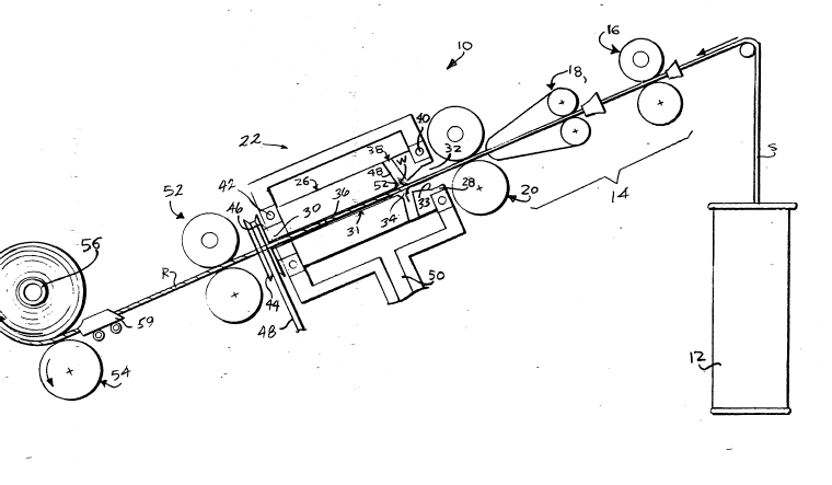
FIGURE 1 is a schematic diagram of the
apparatu~ utili~ed in this invention; and
FIGURE 2 is a schematic side view of roving
produced by the apparatus of this invention.
: ::
With reference to EIGURE 1, a schematic
representation of apparatus in accordance with this ~-~
invention i8 illustrated~
Generally, the apparatus 10 includes a sliver -~
can or bin 12 from which a sliver S is drawn by a ~ -
drafting assembly,14 ~hich includes feed roll sets
16, 18 and 20. The drat system acts upon the
fiber~ in the sliver S in a conventional manner and
feed~ the fibers into the vacuum nozzle assembly
22.
The nozzle assembly 22 comprises a housing 24
'~- - ~`"':''
', ~';" `
20050~8
and an elongat:ed hollow shaft 26 mounted for
rotation therein. The shaft has a first entry end
28 and a second exit end 30. A through passageway
31 extends from the end 28 to the end 30. The -~
passageway includes a first portion 32 adjacent the
first end 28, an interior chamber portion 34 close ~,~
to, but spaced from, the first end 28, and a third ~
portion 36 that extends from the chamber portion 34 -
through the nozzle to the second end 30. The first
or entry portion 32 has an entry diameter of about ;~
3/8 inch (9.5 mm) significantly larger than the 3/16
inch (4.7 mm) diameter of the third or exit portion
36, and is connected thereto by a tapered conical -~
portion 33.
About the periphery of the shaft, at the ~ -~
juncture of shaft passageway portions 32, 36, i.e.,
at the chamber portion 34, there are provided a
plurality of orifices 38 extending from chamber 34
radially outwardly through the shaft 26, to provide --
communication with the interior of the housing 24.
The number of orifices may be varied but is
; preferably within the range of two to 8iX or more. -~
In addition, the passages defined by the orifices
may extend substantially perpendicular to the
passageway 31, or at an inclined angle relative --
thereto.
In a preerred arrangement, the housing 24 is
conn~cted vialinleti~50 to a vacuum pump or other
vacuum source (not shown).
Bearings 40,42 mount the shaft for rotation
within the housing. A pulley or gear 44 is pre~fit ~ -
to an exterior cylindrical surface 46 of the shaft
26 so that rotation of the gear effects rotation of
,~
;~:0~)~018
: .
the shaft 26. Gear 46 is connected to a drive motor
(not shown) or other suitable drive means via belt
or chain 48.
A pair of take-off rolls 52 is mounted adjacent
the outlet end of the nozzle, along with a take up --~
roll 54 and a roving tube 56 upon which the roving R
is wound at speeds of up to 100-150 yds/min. (91-36
m/mm). A conventional transverse motion device 59
is utilized to facilitate winding of the roving on ~
the tube 56. ~--
In use, the fiber mass or sliver S, having a
grain weight of from about 25 grs/yd (23 grFi/m) to
about 220 grs/yd (200 grs/m), is fed in a linear
direction through the drafting assembly 14, after
which the mass is pushed and drawn into the interior
of the nozzle assembly 22. In this regard, it will ~,
be appreciated that the air flow created in the
housing, e.g., via connection of a suitable vacuum
source to the housing inlet 50, assists in drawing
the fibers into the nozzle a~sembly along the linear
feed direction, while they are at the same time ~A~rl;
being pushed by feed roll set 20. `-~
As the fibers pas~ beyond the entry of the
nozzle, some of the fibera, which have free trailing -
ends, are deflected, i.e., radially displaced, by -;-
reason of the air flow into the radially oriented
orifices 38, but are immediately pulled back down by
the continued~linea~ movement ~f the~fiber maas. At ~ ~
the same time, these radially displaced iber ends ~ -
are wrapped around the remaining core fibers by -~
reason of the high speed rotation of the nozzle. It -
will be appreciated that the rotation of the shaft,
simultaneously with the creation of the vacuum in
`- 2005018
- 8
~he radially extending orifice~, will create an air
flow not only radially outwardly but, also in the
direction of rotation of the shaft or nozzle. The
wrapper fibers W, best seen in FIGURE 2, comprice
approximately 5 to 20% of the fibers, and while the
wrapper fibers may have some small degree of twist
applied thereto, the remaining core fibers C have no
twist at all, real or false. It is preferred that
the wrapper fibers compri~e 15% or less of the fiber
ma~s. Control and adjustment of the amount of
wrapper fibers may be achieved through adjustment of
nozzle rpm, vacuum pressure and the number and size ~;
of the radially oriented orifices. .
With reference to Figure 3, there is
illustrated one exemplary nozzle design for use in a
vacuum roving process in accordance with this `-
invention.
The nozzle 60 has an inlet end 62 and an outlet :-
end 64. A through passageway 66 extends through the
nozzle along a longitudinal axis A from the inlet -~
end to the outlet end. A first or entry portion 68
of the passageway includes a constant diameter bore ~ :
~portion 70 and a tapered portion 72 which extends
between the inlet end 62 and an interior chamber
portion 74. The entry portion 68 in this exemplary
embodiment has an inside diameter of about 3/8 inch,
and tapers to a remaining smooth bore outlet portion
; 76 whi.ch`has !an iinsi'de diameter of about 3jl6 inch,
and extends between the chamber 74 and the outlet
~ end 64.
i~ Interior chamber 74 is created at the interface
; of entry portion 68 and outlet portion 76 by
~; intersection with a plurality of, and preerably
:~ 20050~8
..:
....
four, tapered bores 78 which extend inwardly from -~
the circumferential surface 80 of the nozzle. Each
bore tapers from a diameter of about 5/32 inch (3.9 ~-
mm) to about 1/8 inch (3.2 mm), and each bore is
inclined relative to the longitudinal axis A,
preferably away from the inlet end in the radially --
outward direction.
The overall length of the nozzle is about 2
inches (51 mm), and the nozzle has an out~ide ;;
diameter of about 1/2 inch (12.7 mm). Toward the
rearward or outlet end 64 of the nozzle, there is
located a radial flange 82 which may engage a rear -
wall of the housing 24, while a rearward extension -~
84 protrude~ beyond the housing for reception of a
drive gear 44 or other suitable drive means, as
shown in FIGURE 1. ~.
It is to be understood that this invention is
not limited to nozzle designs having only the above .-~-
described dimensions. The dimensions may be -: -
modified as neces~ary depending on the roving
characteristics desired.
The above described process, applicable to both ~-
long and short ~taple fiber roving production, i~ a -;~-~
high speed, yet simple and reliable process, the ~`~
roving product of which is at least equal in qualitv
to that produced by conventiona]. flyer and rub -~
roving processes.
,Wh~ile th!e ihvenition ha~ been descrlbed in ! ~ ~-
connection wit,h what is presently considered to be
the most practical and preferred embodiment, it is
to be understood that the invention is not to be
limited to the disclosed embodiment, but on the
contrary, is intended to cover various modifications
~: .
: .,
2005018 ~ ~ ~
., .:- .
:''',"",'
~: ,,, . ', .,
and equivalent arrangements included within the
spirit and scope of the appended claims.
'~ '.','
.,'. "
' ~ `~ , ,.:~
~ ~ .