Note: Descriptions are shown in the official language in which they were submitted.
20050~~6
PIVOTAL ADAPTER FOR BIPODS AND ATTACHMENT THEREFOR
Background and Summary of the Invention
The present invention relatEas to bipods and mounting
devices therefor. More particularly the present invention
relates to pivotal bipod assemblies and novel mounting
assemblies for attaching a bipod to a firearm such as a rifle
or the like.
Modern firearms, such as rifles in particular, may be
more accurately and conveniently hired by the user if the
firearm is equipped with a bipod device for supporting and
steadying the barrel. Bipods may be fixedly or removably
mounted onto firearms and have been found to be most
convenient if they can be somehow retracted in a storage
position when they are not in use,. Lightweight bipods and
mounts therefor are taught in my prior U.S. Patent Nos.:
3,327,422 issued June 27, 1967; 4,470,216 issued September 11,
1984; 4,625,620 issued December 2, :L986; and 4,641,451 issued
February 10, 1987; the disclosures of which are incorporated
herein by reference thereto. While the bipods disclosed in
these prior patents are extremely convenient, may be adjusted
and retracted and include various advantageous mounting
assemblies, there remain certain desirable improvements which
have not been heretofore recognized but are addressed in the
present invention. For instance, while these prior bipod
devices are adjustable for various forward and reverse angles
with respect to the barrels and are also adjustable with
.200~i04~
respect to the bipod leg length which may be retracted or
extended to adjust to various shooting situations, the bipods
require time consuming adjustment which time is not always
available in hunting and other shooting situations. Also,
these bipods do not readily adapt themselves to slanted
surfaces and irregular surfaces whE~n in use . This increases
the frustration level of the user and/or chances of missing a
shot due to the excess time required for finding a suitable
rest for the firearm bipod during shooting and for adjusting
the bipod to accommodate various irregular surfaces.
A bipod which is pivotal in a plane generally
transverse to the barrel of a firearm is shown in U.S. Patent
No. 2,489,283. However, the utilization of such a pivotal
bipod has proven to be problematic. While this bipod may be
useable on slanted or uneven sur:Faces, no matter what the
position the barrel and gun tended to be prone to teetering
thus, allowing the firearm to be unstable and at least
partially defeating the purpose of the bipod.
While these types of bipods may be retracted for
storage and carrying they have had a tendency in the past to
rattle about and create other unwanted noises when in use or
while in the retracted position.
A further disadvantage is that while many of these
bipods are designed for attachment at a sling swivel stud or
other places adaptable for mounting of bipods found on many
firearms, there is an increased need for a universal adapter
which may be attached or removed fx-om a variety of firearms as
2
200041,
desired by the firearm owner and without undue wear and tear
on the firearm.
Additionally, it has been a coal in the art to provide
a quick release mechanism whereby the bipod extension may be
easily removed leaving a bipod mounting attachment on the
rifle. Also, in the past there has been a need to provide a
mechanism for releasable attachment on a semi-automatic rifle.
In the present invention a pivotal bipod adapter is
provided which allows the legs of the bipod to pivot in a
single plane which is generally perpendicular to the gun
barrel direction. This allows the shooter to place the bipod
and gun on an uneven surface quick7.y and without unnecessary
canting of the rifle. In the pivotal bipod assembly of the
present invention the pivotal adapter is configured such that
undesirable rattling type noises from the bipod adapter are
diminished substantially. Additionally, in accordance with
the present invention there is provided a universal bipod
mount assembly which may be advantageously attached to a rifle
without any necessary modification or addition of sling
swivels or other nonremovable type fixtures to a firearm. The
adapter of the present invention also includes a quick release
feature whereby the bipod and moving parts thereto may be
easily detached from a firearm. A novel apparatus for
attaching a bipod to a semi-automatic rifle is also provided.
According to the present invention there is provided a
pivotal adapter assembly for pivota:Lly attaching a bipod to a
firearm. The pivotal adapter assembly includes a base portion
3
2005041
which has a means for providing a pivotal engagement with a
mounting bracket of a bipod. A means for attaching the base
portion to the firearm is also included. The mounting bracket
for attachment to the bipod base includes portions thereof for
cooperating with the base portion, which portions provide for
pivoting of the mounting bracket: in a single plane or
direction generally transverse to the direction of the barrel.
Also, provided in the present invention is an apparatus
for removably attaching a bipod to a firearm. The apparatus
has a base with a facing means fot contoured cradling of the
forestock of a firearm. A strap member is provided for
allowing releasable attachment of the base to the firearm.
The strap is connected to the base and encircles portions of
the firearm. The strap includes a means thereon for clampingly
engaging the firearm between the strap and the facing means.
The apparatus also includes a means. for attachment of a bipod
assembly to the base portion.
A bipod adapter for a semi-automatic firearm is also
provided. A bipod adapter is provided for use on a
semi-automatic firearm which firearm includes a gas block
having a threaded bore therein and a fore-end cap adapted for
being fastened to the gas block with a fastener. The bipod
adapter of the present invention includes an adapter base with
a borg therethrough. The base is associated with the firearm
generally perpendicular to the longitudinal axis of the barrel
when in assembled relationship with the firearm. Portions of
the adapter base are provided for substantially engaging
4
~oa5o~s
portions of the barrel for inhibiting rotational movement of
the bipod adapter. A fastener is included for providing axial
forces against the base for fastening of said fore-end block
and said base to said gas block. A portion of the bipod
adapter is provided for the attachment of a suitable bipod.
Brief Description of the Drawi_nas
Figure 1 is a planar view of the pivotal adapter
assembly of the present invention partially in phantom:
Figure 2 is a sectional view taken along line 2-2 of
Figure 1;
Figure 3 is a sectional view taken along line 3-3 of
Figure 1;
Figure 4 is a sectional view partially broken away
taken along line 4-4 of Figure 1;
Figure 5 is a planar view partially in phantom showing
an alternate means for connecting the pivotal adapter to a
firearm;
Figure 6 is a sectional view taken along line 6-6 of
Figure 5;
Figure 7 is a planar view pay.~tially broken away showing
an alternate mounting configuration of the pivotal adapter of
the present invention:
Figure 8 is a sectional view taken along line 8-8 of
Figure 7;
~oo~o~ s
Figure 9 is a planar view partially in phantom of the
mounting assembly for removably attaching a bipod to the
firearm of the present invention;
Figure 10 is a sectional view taken along line l0-10 of
Figure 9;
Figure 11 is a sectional view taken along line 11-il of
Figure 9;
Figure 12 is a sectional view taken along line 12-12 of
Figure 9;
Figure 13 is a sectional. view of an alternate
embodiment of the mounting assembly of the present invention;
Figure 14 is a planar view partially broken away and
partially in phantom of an alternate embodiment of the
mounting assembly;
Figure 15 is a sectional view taken along line 15-15 of
Figure 14;
Figure 16 is a sectional view taken along line 16-16 of
Figure 14;
Figure l7 is a planar view partially broken away and
partially in phantom of a still further embodiment of the
mounting assembly of the present invention;
Figure 18 is a sectional view taken along line 18-18 of
Figure 17;
Figure 19 is a sectional view taken along line 19-19 of
Figure 17;
6
20d50~~6
Figure 20 is a planar view partially broken away of a
bipod adapter for attachment of a bipod to a semi-automatic
rifle;
Figure 21 is a sectional view taken along line 21-21 of
Figure 20;
Figure 22 is a side view partially in phantom and
partially broken away of a pivotal b~ipod assembly mounted on a
firearm including a tensioning assembly for adjustment of
pivotal resistance;
Figure 23 is a rear view partially broken away of the
assembly shown in Figure 22;
Figure 24 is a detailed bottom view partially in
phantom of the assembly of Figure 22; and
Figure 25 is a detailed cross-sectional view of the
tensioning adjustment assembly talken along line 25-25 of
Figure 23.
Detailed Description of the F~referred Embodiments
For purposes of illustration, various embodiments of
the present invention are shown in the drawings as attached or
mounted to a rifle. One skilled in the art will readily
recognize, however, that various embodiments of the present
invention are applicable to other types of firearms as well.
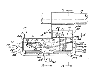
Figure 1 generally illustrates a pivotal adapter
assembly 10 for pivotally attaching a bipod to a firearm.
Pivotal adapter 10 includes a base portion 12 which has a
means 14 for providing pivotal engagement with a mounting
7
~OU5U~~6
bracket 16. A means 18 for attaching the pivotal adapter to a
firearm is also provided. The mounting bracket 16 is pivotal
in a single plane about the base portion 12 through
cooperating portions 20 of the bracl~;et 16.
The base portion 12 includes a forward portion 26 and a
rear portion 28. Pivot pins 30 and 32 are provided at
portions 26 and 28 of the base portion 12. Pivot pin 32 is
slideably positioned in bore 34. laore 34 is longer than the
pin 32 such that a spring 36 is disposed in the bore and
thereby facilitating extension and retraction of pin 32. A
stopping protrusion 38 is provided which extends into slot 40
in the base portion 12. Thus, the pin 32 may be depressed
into the bore 34 and thereafter extends outward until pin 38
is stopped in slot 40 from further outward movement.
Pin 30 is press fit in base portion 12 or otherwise
secured thereto. The base also includes a spring member 42
operably attached in indentation 44 in the base 12 by way of a
fastener 46. Spring member 42 includes a base portion 48 and
spaced spring tongues 50 and 52 which are generally folded
back over the base portion 48 as shown in Figure 1.
Mounting bracket 16 includes upwardly disposed front 54
and rear 56 flanges thereon. These flanges include bores 24
and 25 therein for engagement with pins 32 and 30
respectively. Bracket 16 also includes upwardly disposed side
portions 58 and 60 which are operatively positioned to engage
spring tongue portions 50 and 52 respectively. A sling swivel
mounting screw 62 (also referred to herein as 'a quick
8
~005U~n
detachable stud) is provided in the: base of mounting bracket
16 for securement of a bipod 64 thereto as shown in my prior
patents. Bipod 64 includes upwardly directed portions 66 and
68 which engage angled portions 70 and 72 through pads 74 and
76. A roll pin 102 is provided asp a stop to prestress the
tongue members 50, 52 of spring 26 and also to provide for
only limited outward movement of the spring tongues 50 and 52.
The embodiment shown in Figt;~re 1 is shown with means
for attachment to a bayonet stud mount found in many military
type firearms. Thus, referring to figure 1 a rifle barrel 78
which includes a bayonet stud mount 80 attached thereto is
engaged by an attachment portion .B2 of the base 12. The
attachment portion 82 is shown in more detail in Figures 3 and
4. The attachment portion 82 includes a channel 84 therein
for sliding onto the "T" shaped bayonet stud mount 80.
Bayonet stud mount 80 includes a pair of grooves 86 and 88
running vertically along either side thereof. A locking catch
90 is provided on the attachment portion 82 which includes a
locking engagement pin 92 for engaging a slot 88 of the
bayonet stud mount 80. The locking catch 90 is spring mounted
by way of a shoulder screw fastener 94 fastened into the
attachment portion 82 with a helical spring 96 disposed
between the catch 90 and the head of screw 94. A bore 98 is
provided in catch 90 whereby the catch 90 may be advanced
along the length of the shoulder screw 94 for removing pin 92
from engagement with groove 88. A set screw 100 is also
9
~O~SUn'~V
provided in the base portion for providing secure, relatively
recoil resistant attachment to the bayonet stud mount.
In operation, the assembly 10 is mounted on the bayonet
stud 80 by first retracting the pan 92 to be even with the
inner surfaces of the mounting portion 82 by way of actuating
the catch release 90 away from portion 82. The portion 82 is
then axially moved along portion 80 until the pin 92 engages
slot 88. Thereafter set screw 100 is shored down to ensure a
tight fit between the base and the bayonet stud mount 80, set
screw 100 also acts as a recoil atop and helps to prevent
loosening or damage of the mount d.ue to recoil forces during
firing of the firearm. Thereafter, a bipod may be attached to
fastener 62 by way of pin 63 such as shown in my prior
patents.
The bracket 16 is pivotal .about pins 30 and 32 in a
single plane which is preferably a direction transverse to the
axial direction of the barrel. This provides limited movement
such that if the shooter is on a t~~lted or uneven surface the
bipod legs can be easily situated by pivoting of the bracket
as needed to sturdily engage the tilted surface. Tongue
portions 50 and 52 of the spring 26 operatively engage the
portions 58 and 60 of the base such that tilting is
accomplished without teetering, collapse or other mishaps.
Springs 50 and 52 also provide fo:r a relatively rattle-free
construction when transporting or moving the firearm thus
reducing unwanted noise generally associated with bipods.
While a prestressed flat spring is ahown in the drawings it is
l0
200504'
within the scope of the present invention that other types of
springs and stop arrangements could be used without deviating
from the scope of the present invention.
The assembly of the present invention allows easy
removability of the bipod and mounting bracket 16 by way of
simply depressing or retracting the pin 32 and easily removing
the bracket over the end of pin 30. Thus, the base portion 12
may be allowed to remain on the firearm without the necessity
of having a bipod attached thereto.
Figures 5 through 8 disclose alternate embodiments for
connection of the pivotal adapter assembly of the present
invention to conventional firearms. For instance, in Figure 5
there is shown an attachment to a firearm by way of the sling
swivel stud 104. Sling swivel studs 104 are conventionally
mounted in a forearm stock 106 of a firearm by way of a nut 108
embedded or otherwise operatively associated with a bore in the
stock. These are conventionally used for attaching a rifle
sling or the like to a firearm. The present invention has been
modified for use in attaching the pivotal adapter assembly by
use of the stud 104 and a stock engaging portion of the base
110. The engaging portion includes a cradling portion 112 for
cradling of a firearm stock. Cradling portion 112 may include
pad portions 114 and 116 to prevent marring or other possible
damage to the stock 106 of the firearm. Thus, in operation the
stud 104 is passed through spring portion of base 110 and
operatively fastened into nut 108. This holds the adapter
assembly securely on the firearm.
11
';,'~.
-- r 2oo5o~g
In Figure 7 an alternate <~ssembly is shown for barrel
mounting of the pivotal bipod adapter assembly of the present
invention. As shown therein an upper barrel engaging bracket
116 along with a lower barrel engaging bracket 118 are provided
for clampingly engaging the barrel of a firearm. Fasteners 120
and 122 are provided for clamping the barrel 124 of a rifle
therebetween. Set screw 117 in this embodiment is provided to
ensure a secure recoil-resistant grip on the barrel 124.
The present invention also includes a mounting
apparatus generally shown at 200 through which the bipod
adapter 210 may be advantageously adapted to a variety of
firearms. This mounting apparatus provides a nonpermanent and
readily removable mounting for the bipod adapter or bipod on a
firearm. The base portion of bipod adapter 210 includes a
forestock cradling portion which has pads for cradling the
forearm without damage to the forestock. The mounting
apparatus 200 includes a base 212 having facing means 211 for
contoured cradling of the forestoc:k of the firearm. A strap
means 213 is provided for providing releasable attachment of
the base 212 to a firearm. The strap means 213 is connected to
the base portion for encircling of the firearm. A means 215 is
provided on the strap means 2:L3 for reducing the area
encompassed by the strap means 213 thereby allowing for
clamping engagement of the firearm between the strap means and
the facing means.
12
200504y
Referring to Figure 10 the strap means 213 includes a
pair of outer strap members 218 and 220 which are connected to
the base 210 by fasteners 222 and 224. As shown in the
drawings the strap members 218 and 220 are operatively curved
to provide for the contours of they forestock. These straps
include upwardly directed flanges 226 and 228 respectively
which have bores therein allowing a fastener 230 to be inserted
therethrough. An inner barrel engaging saddle strap member 232
is provided for engaging the barrel of the firearm. Saddle
strap 232 includes an arcuate portion 234 and a flange portion
236. As can be seen more clearly in Figure 9 the flange
portion 236 includes an opening 238 therein which allows the
strap member 218 to be passed therethrough.
In operation, the straps 21.8, 220 are placed on either
side of the firearm axially over the barrel without the
inclusion of saddle strap 232 or fastener 230. After
positioning in the proper location the saddle strap 236 is
positioned as shown in Figure 10 and the fastener is passed
through the bores in flanges 226 and 228. Thereafter fastener
230 clampingly engages the forestock between pads 214 and 216
and the saddle strap 232 by tightening of the nut 229 which
pulls flanges 226 and 228 together.
Referring to Figure 12 a recoil stop 250 may be
advantageously provided in the mounting apparatus of the
present invention. Recoil stop 250 includes the member 252
which has an arcuate surface 256 at an end thereof. A
threaded bore 256 is provided in member 252 for securing the
13
~:~Aø~:~~
ay ~
20~DSU~~U
recoil stop to the face of the bipod adapter base 212. In
operation the mounting assembly is ;positioned near the swivel
stud 258 of a firearm such that arc:uate portion 254 directly
abuts swivel stud 258. The mountings assembly is then attached
and clamped into position and the screw 260 is thereafter
tightened to secure the recoil stop to the assembly.
In operation, recoil stop 250 assists in the prevention
of problems associated with rifle recoil such as changing the
position or otherwise altering the position of the removable
mounting assembly.
In an alternate embodiment .as shown in Figure 13 the
strapping means 313 is a singular outer strap member 317 with
an upper flat surface 319 having a bore 321 which has a nut
like member attached therein. The inner saddle strap member
332 is generally "U" shaped having barrel engaging portions
333 and 335. In this embodiment claw portions 337 and 339 are
attached to the base 310 by way of fasteners 324 and 322.
Claw portions 337 and 339 have curved end portions which
engage openings 341 on the strap portion.
In operation, the mounting member may be again slid
axially over the barrel or the base portion may be positioned
and the strap having the saddle positioned therein may be
placed over the barrel with the lower portions thereof spread
apart and thereafter placed into position on claws 339 as
shown in Figure 13. When in position the saddle 32 is
generally retained onto screw 343 by way of fastener 345.
However, the bore in the saddle is wide enough such that
14
~_ 2005046
turning of screw 343 will merely bear against the saddle
portion 332 for clampingly engaging the barrel but will not
create rotational forces in strap 33.2.
The embodiment shown in Fi<3ures 14-16 is similar to
that shown in Figure 13, however, in this case the installation
is shown on a military type rifle wlZich includes a barrel 478
surrounded by a stock 479 and a front portion 401 such as
commonly found in many military type rifles.
Referring now to Figures 14 through 16 the embodiment
of this invention is generally the same as that shown in Figure
13. The mounting assembly 400 includes an outer strap 419
which is a singular strap. The inns=_r saddle strap member 432
includes stock engagement portion: 433 and 435 which are
slightly more angular in an outward. direction than those for
engaging a barrel since a stock will generally be wider than
merely the barrel. Additionally, a distinction between this
and the embodiment shown in Figure 13 is that pad portions 414
and 416 are directly a part of strap 419. Strap 419 includes
portions 403 and 405 which engage the' base 410 through openings
407 and 409 therein.
The recoil stop 350 in this embodiment includes a
member having an upturned flange 360 which includes a "U"
shaped opening 362 therein for engaging the portion 401 of the
rifle. The recoil stop is again held into place through
fastener 360 engaging a bore 356 in recoil stop 350.
Referring now to Figures .L7 through 19 there is a
further alternate embodiment of the present invention. In this
_.
20050~a
embodiment the strap means 513 includes a nylon cord 519 or the
like which encircles the barrel o:r stock of the rifle. As
shown in the figures cord 519 is wrapped around a suitable
flange 555 of the base 510 and thereafter secured in cord
retainer 557. Cord retainer 557 is generally a cylindrical
member with threaded bores on its axial ends. Through-bores
559 and 561 are provided in the member 557 for passing the ends
of cord 519 therethrough. Through-bores 559 and 561 are in
alignment with and overlapping the threaded bores in the axial
ends of cord retainer 557. The fasteners 563 and 565 are
provided for securing the cord in member 557 by combining the
cord therein since the bores in the axial ends are lined with
bores 561 and 569.
On the opposite flange 56i', base 510 includes a bore
573 through which fastener 569 may be inserted.
Member 557 includes a thrE~aded bore 571 therethrough
which may be operatively aligned with fastener 569 when the
cord is in position on the firearm. In operation, the cord is
situated and secured into the member 557 and this is slipped
over into engagement with the rifle stock. Thereafter fastener
569 engages the bore 571 of member 557 and may be tightened
down in order to reduce the area encompassed by the cord and
stock engaging portion to thereby c:lampingly engage the rifle.
As in the other embodiments a recoil stop 450 such as that
shown in the other embodiments may also be provided.
While nylon cord or the like may be advantageously used
in the present invention various other flexible strapping
16
... ~2oo5o4s
materials may be used in light of these teachings. For
example, the use of wire, cable, cloth straps or other flexible
materials could advantageously be used in the present invention
without deviating from the scope oi' the present invention.
Referring now to Figures 20 and 21 there is provided a
bipod adapter for use on a semi-automatic rifle.
Semi-automatic rifles produced today by companies such as
Ruger, Garand, BAR and Heckler & Koch and others, generally
include a gas block 600 attached t:o a barrel 602. Gas block
600 serves two purposes on a firearm. Gas blocks such as gas
block 600 primarily provide the means for discharged gas
produced from the firing of a live :round through the firearm to
actuate the mechanism to eject spent shells from the chamber of
the firearm. A second purpose i~~ that the gas block has a
threaded bore 604 which may be engaged by a fastener such that
the fore-end cap 606 secures the forestock 608 of the firearm
to the firearm.
In the present invention there is provided a bipod
adapter 610. Bipod adapter 610 includes an adapter base 612.
The adapter base 612 includes a portion 614 defining a bore
therethrough. When assembled on t:he firearm, the base 612 is
generally perpendicular to the longitudinal axis of the barrel
602.
Arcuate cut-out portion 61E; of the adapter base 612 is
for substantially engaging portions of the barrel 602 for
inhibiting rotational movement of the bipod adapter 610.
17
"~j...?a
... _.__......_...__~~._._.-.__..~...~.~.-..~...,.~.-..~.............. _ _...
2U~SU9~6
Shoulder screw 617 is provided for presenting axial
compression forces against the adapter base 612 and fore-end
cap 606 for securing fore-end cap 606 and forestock 608 in
position on the firearm. Shoulder screw 617 includes a
shoulder portion 618 which engages l:he portion 614 forming the
bore in adapter base 612.
Bipod adapter 610 includes an attachment flange portion
620. Attachment flange portion 620 includes a pair of
upwardly turned side edge portions 622 and 624 which provide
reinforcement for the attachment flange portion 620. As shown
in Figure 20 the bipod adapter 610 may provide a means for
attachment of a pivotal bipod adapter as described above to a
semi-automatic firearm. In the alternative, this novel bipod
adapter would be useful in mounting other types of bipods to
semi-automatic firearms. For instance, the flange portion 620
could be modified to provide for attachment of a standard
bipod such as those of my prior designs which are attachable
to a quick detachable stud with a bore therethrough (such as
quick detachable stud 628). This modification may be
accomplished by forming the flanges portion 620 out of flat
sheet metal. In this alternate embodiment the portion below
the plane A-A would be absent and a quick detachable stud
would be attached in the place of screw 626.
The bipod adapter for a semi--automatic firearm provides
for quick and easy attachment or removal of a bipod from a
semi-automatic firearm without the: necessary addition of a
permanent mount thereto.
18
~0~504E~
Referring now to Figures 22 through 25, also provided
for in the present invention is a pivotal assembly 710 for a
bipod for a firearm which includes a spring assembly 712 for
providing resistance against off center rotation of the gun on
the bipod and includes a means 714 for adjusting the tension
about the pivotal point for providing variable resistance
against pivoting.
This pivotal bipod provides for all of the advantages
previously set forth with respects to the pivotal bipod
adapter. Additionally, the pivoting can be tensioned to
reduce rattling which might otherwise be present due to play
in the pivotal assembly 710. Tensioning of the pivotal
assembly also results in advantages in that depending on the
weight of the firearm more or less tensioning can be used to
prevent the tendency of teetering.
The pivotal assembly for a bipod 710 is shown as used
on a "strut" type foldable bipod assembly such as that
disclosed in my U.S. Patent No. 4,625,620. However, the
pivotal bipod mount would also be useful with other bipods
whether retractable or fixed. As an example, the pivotal
assembly is equally suitable for u::e with a retractable bipod
having over-center springs such as that shown in my U.S.
Patent No. 3,327,422.
The pivotal assembly 710 includes a base portion 715
which is attachable to a quick detachable stud 716 of the
firearm 718. Base portion 715 includes a cylinder 720
attached at a rearward portion. Cylinder 720 includes an
19
200~0~46
axial bore 722 therethrough which is generally parallel in its
alignment with the barrel of the firearm 718.
A leg support base 724 is provided. Leg support base
724 includes downwardly extending aide portions 726 and 728
which are inclined relative to a plane encompassing upper
surfaces 730. Rearward portion 732 generally extends
perpendicularly from the planar surface 730 for connecting the
side portions 726 and 728 and also extends in a plane which is
generally perpendicular to the barrel axis.
A pair of bipod legs (727, 729) are rotatably attached
to the side portions 726 and 728. Forward leg stops 734 and
736 are provided as stops against which the bipod legs abut in
the retracted position (shown in phantom in Figure 22).
Rearward leg stops 738 and 740 are provided for removing play
in the legs when in the extended position, thus contributing
to a reduction in potential rattling in the assembly.
Preferably, the rearward leg stops are made of a resilient
material such as rubber, nylon or elastomer material which
allows these leg stops to act as shock absorbers when
actuating the bipod legs into the extended position.
Referring now to Figure 25, the means for adjustable
tensioning of the pivotal assembly T14 is shown in detail. In
particular, a shank 742 is attached to rearward portion 732.
Shank 742 has a rounded exterior such that it cooperates with
bore 722 in cylinder 720 to provide pivotal engagement between
the leg support base 724 and base 715. Shank 742 includes an
axial bore 744. Threaded rod 746 extends through the bore
f 20050 ~~
744. Threaded rod 746 includes a bore 748 at a first end and
is threaded at the other end. A pin 750 is provided for being
press fit in the bore. The pin 750 engages a slot 752 in
slotted washer 754 for retaining the washer in non-rotatable
engagement with respect to threaded rod 746. A nut 756 engages
the threaded portion of rod 746. In operation, nut 756 acts to
provide variable pressure of washer 754 against cylinder 720
and nut 756 against shank 742 thE~reby biasing cylinder 720
against rearward portion 732 oi_° leg support base 724.
Preferably, nut 756 is knurled on its outer periphery to allow
easy adjustment of the tension by hand. Lock nut 758 is
provided to shore-up the tensioning position of nut 756 when a
preferred adjustment is reached by the user.
A spring member 760 is provided which is attached to
the base 715 such as by riveting or the like at connection 762.
Tongue portions 764 and 766 extend rearward toward the bipod
legs and downward to meet the upper surface of the side
portions 724 and 726 of leg support base 729. This arrangement
provides spring tension against pivoting of the leg support
base 724 and acts as a centering spring such as that disclosed
above in other embodiments of the present invention.
The foregoing description and accompanying drawings
illustrate merely exemplary embodiments of the present
invention. Various changes, modifications and variations may
be made therein without departing from the spirit and scope of
the invention as defined in the following claims.
21