Note: Descriptions are shown in the official language in which they were submitted.
~~t~'~'~
COhIPpSITES OF Pl~PER A1ND PLP,STIC FILtdl, CORRUGATED
PAPERDOARn Tt~CORPORATTNC SATD CON1P0~2TE$,
AIeTD METHODS OF I~IAK~NG
Field o~ the Inyention
S 'his invention relates to composites of paper and
plastic film, to corrugated pt~perboard inG~rporating such
a composite as a liner adhered to the corrugated medium,
and to methods of making the composites and the corrugated
paperboard. The invention is ~rartiaular~.y useful in the
packaging field in the form of containers, but it finds
advantageous utility in the fabrication of ether productr~,
such as point-af-purchase displays, wall panels, past~rs,
and the like, where a combination of the unique structural
features of the invention and high quality graphics is
desired. The invention is particularly felt, to Satisfy a
long-øelt need in the area of falling cartons for
packaging, whether as primary packaging or secondary
packaging, in composite form ar ag a liner for corrugated
paperboard. Although the composite of iaaper and plastic
film is highly useful and advantageous in itself, it is a
particularly important characteristic of the composite
that it can with stand the conditions in the "double
beaker" part of a conventional corrugating machine such
that it can be combined with a single faced corrugated
board to form a double faced Corrugated beard witha~.tt
material deterioration of the oomprasite, which, tQ my
knowledge, has previously been considered impossible as a
practical matter, important char$cteristics of the aam-
posite alone or as incorporated in corrugated paperboard
include scuff and scratch resistance, strength, stretch
resistance, tear resistance, separation resistance,
resistance to "checking" (axacking in a scare lin~) an the
forming p~ blanks for folding cartons, surface smoothness
and gloss, graphics quality and durability, fragrance
barrier quality, and moisture barrier quality,
2
~tl~t~ s
aackc~xound
Tt is known in the packaging and other arts to form
a packaging material in the farm of a laminate of paper
and plasf.ic film secured together by an adhesive. for
instance, particularly in the field o:~ flea~ible packaging,
various films have been laminaf.ed to paper with various
adhesives, of which polyethylene is one exempla. ~'or
instance, T am aware that a flexible packaging mate vial
has bean made by laminating ".Mylar" polyester f i1m to pro-
to duct of E. T. Dupont ~eNamours & Co, hnc., Ydilmington,
Delaware, U. S. A.> to thin high-quality paper using a
polyethylene adhesive. I am also aware of pear p. S.
patent No. 4,254,173 issued March 3, 1981, which proposes
a secondary contain~;r packaging material te.g., a six-pa~ek
can or bottle wrap) comprising a paper material laminated
to a plastic film. The patent discloses various films,
including polyester, vari~rus papers such as kraf~t paper of
various weights, and various adhesives, including
polyethylene, to bond the film to the paper. xt is
disclosed in this patent $nd generally known otherwise
.hat. the film can be reverse printed with graphics prior
to lamination. To my knowledge, all prior proposals have
used the adhering agent only as an adhesive and, thus,
have used only that amount necessary to achieve adhesion
of the two laminated components. I do not find in the
prior art any recognition or appreciation of the possibi-
lity of using the adhering agent not just as an adhesive
but rather as an impregnant and surface enhancer go as to
achieve the Characteristics and advantages of the present
inv~entton.
It is a basic purpose of the present invention to
provid~a an improved composite of paper or paperboard and
plastic film in which the adhering agent is used not
merely as an adhesive, but rather as an impregnating and
bonding agent and as an enhancer of the paper sur~ac~ by
essentially farming a new surface. ~y operating under con-
ditions which ensure substantial impregnation of the
adhering agent into the paper, but with a substantial part
overlying the surface of the paper and firmly adhering to
the plastic film, Z obtain a product which is highly
resistant to separation, which enhanoes and protests the
graphics quality of reverse printed film or a painted
paper surface, which will withstand the rigors of the
double-backer portion of a conventional corrugating
l0 machine, which minimizes the norms? adverse effects of
scoring, cutting, folding, etc., in the formation of a
carton, and which generally is a new and improved product
capable of many uses.
features and As ects of the" Invention
In making a composite of paper and plastic film in
accordance with my invention, a web of paper arid a web of
plastic film are passed into and through the nip of a pair
of nip rolls, and a layer of molten polymer impregnating
and bonding agent is extruded into the nip between the
webs an the entry side of the nip, One ar mare of the
speed of the webs, the temperature of the molten polymer,
the pressure or spacing of the rolls at the nip, and the
rate of extrusion is or are controlled relative to the
porosity and surface characteristics of the paper web such
that a substantial portion of the molten polymer impreg-
nates partially into and becomes part a~ the paper wsb,
and a substantial portion lies outwardly of the surface o~
the paper web and solidifies to farm an enhanced surface,
which is essentially a new surface, to which the film is
bonded and on which it is supported clear of the paper
surface. there is collected Pram the nip rolls a com-
posite comprising paper partially impregnated with solidp
ified polymer, a contiguous layer of solidified polymer
having the new surface outwardly of the paper surface, and
tho plastic film banded to the new surface. In one pre-
. 4
~~~ a(~'~~~
ferred practice of the invention, the inner surface of this
~ilm is reverse printed with desired graphics by any a~
several printing processes. Howavar, the .fnvent~,on also
provides improvements where the printing is done on the
surface of the paper web itself, since the printed paper
surface is protested against scufffng of the print, and
hence less ink can be used. ~referak~ly the molten polymer
comprises polyethylene, the film is biori$nted, and the
paper is kraft paper. A particularly preferred film is
bioriented polyester. Adherence of the Components in the
resulting composite is such that peeling essentially is
not possible, in that the fibers of the paper will
separate before the solidified polymer or the film will
peel from the paper. As mentioned above, one of the most
important and, indeed, surprising features of the com-
posite is that it can be passed through the doub3,e-back~r
portion of a conventional corrugating machine to form the
outside liner of a double-faced corrugated paperboard,
which typically involves movement of the exposed face of
the film along a hot plate section maintained at tem-
peratures up to about 350°F. Equally as important and
surprising is the ability of either the composite ar the
corrugated paperboard of which it forms the outer 7,iner
surface to withstand the rigors of formation into folding
carton blanks and folded cartons with little ax no separa-
tion, "checking", etc. The graphics quality which Gan be
obtained and maintained in thQ end prpduct is believed to
be decidedly suparior.
While the Eoregaing sets forth some of the basin
features and aspects of the invention, subsidiary features
and aspeots of varying degrees of importance will bra
brought out in ar apparent from th~ ensuing description
and illustration of preferred embodiments.
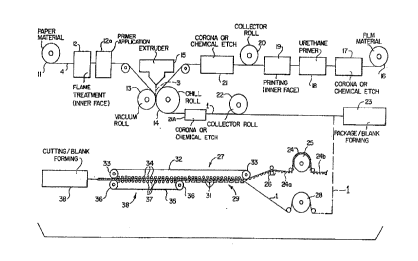
Brief Description of the brawinr~s
Figure 1 is a diagrammatic illustration of apparatus
5
~~~~~'r ~
and steps involved in praeticirig preferred embodiments of
the invention, including the fabrication of the composite
arid optional incorporation of the composite in a double-
faced carrugated paperboard;
h'igure 2 is a schematic ~ectian (not to scale) of t,ha
preferred embodiment of the composite; and
Figure 3 is a schematic section of a double-faced
corrugated paperboard in which the composite is incor-
porated as the double face liner.
Deseriptipn of the Preferred Embodiments
Referring to Figure 2 of the drawings, a composite
of the invention is shown at 1. The composite includes a
paperboard substrate 4, a reverse printed plastic film a,
and an impregnating and bonding polymer 3. As shown, the
Z5 polymer has been Caused to partially impregnate the paper
4 so as to farm a substantial thickness of impregnated
paper 6. tit the same time, a substantial portian of the
polymer 3 lies outwardly of the paper surface and essen-
tially forms a new and enhanced s~urfaee relative to that
of the paper, the reverse printed film 2 being supported
an and firmly adhered to the new enhanced surface provided
by the polymer 3. The impregnation depth of the polymer
into the paper is indicated. at 5. Tha composite. 1 differs
markedly from the prior art of which r am aware because of
the degree of impregnation of the polymer into the paper
and the extent to which the new enhanced surface provided
by the polymer lies outwardly of the paper surface so as
to prevent or at least minimixe surface characteristics of
the paper z~ffecting the reverse printed film 2. zn the
conventional prior art laminates of which I am aware, the
conventional adhesive does not impregnate the paper at
least to any substantial extent, and 'the fibrous character
of the paper surface adversely affects the appearance of
the film. This latter characteristic of the prior art aan
be and probably has been alleviated to some extent by
5
~~~~'~~
using a high quality clay-coated paper as the substrate.
I~iawever, clay-coated paper is expensive and still would
not provide the enhanced surface provided by the overlying
polymer in accordance with the present invention. Also,
play-coated paper is relatively less porous than conven-
tional kraft paper such that it can be more difficult to
obtain the desired impregnation of the polymer. Htithout
substantial impregnation, together with the overlying
polymer, the product simply would not withstand the rigors
of folding car~.on formation while provida.ng a high
quality, commercially viable end product. I~or would it
withstand the conditions in the Bauble-backer portion of a
conventional corrugated board making machine.
Figure 2 illustrates a double-faced corrugated paper-
board structure which is conventional apart from the
incorporation of the composite of the invention as the
double face l.lner, as Shawn at 10. The otherwise conven-
tional corrugated paperboard structure 7 comprises a
corrugated medium 9 and a single face liner 8. While
Figure 3 illustrates only one corrugated medium 9 and one
single face liner 8, the combination of which is typically
known as single faced corrugated board, it will be
understood that there are known in the art corrugated
paperboard structures consisting of two, three or mare
single faced boards glued to each other, the single face
liner of one single faced board being glued to the corru-
gated medium of another single face liner so as to form a
built-up structure, For instance, such a combination of
three single faced boards is ty~aiaally referred to as
tripls walk. beard. xt is to be understood, therefore,
that the present invention encompasse$ alno such built-up
structures in which the composite 10 forms the outer
liner, such a built-up structure being exemplified by p~,C-
turing Figure 3 as including one, two or mare additional
single faced boards above and adhered to single face liner
7
(~~r f~
6 or to the correspandinan'~e ace liner of a further
single faced board.
Referring now to Figure 1, there is illustrated in
the upper part of the figure a diagrammatic representation
of apparatus for and the process of making the compcasite
of paper and plastic film. collector rolls are shown at
20 and 22 to reflect the fact that various parts o~ the
process may be formed at different times and in different
locations, although the process could be continuous. From
the point represented by the second Collector roll 22, the
completed composite can be passed to apparatus, schemat-
ically indicated at 23, for formation into a package or
blank or any other form, typically involving cutting,
scoring, slitting, etc. Alternatively, the completed com-
posits 1 can be passed to a corrugated board making
machine for incorporation as the outside liner of a double
faced corrugated board. Thus, the lower part o~ the
figure, connected by the broken line, illustrates a typi-
cal "double backer" part of a conventional corrugated
board making machine as shown in, for example Griffith et
al U. 6. ,patent 3,39,901 dated March 25, 19f9. From this
"double backer" part of the machine, the double faced
corrugated board is passed to a conventional cutting or
blank forming station shown at 38 where it may be cut into
sheets, formed into container blanks, etc.
As shown in the upper part of the figure, paper
material, typically conventional kraft paper or paper-
board, is led from a roll 1.1 through a flame treatment
station 12 where the inner surface (the upper surface as
viewed in Figure 1) is flamed by a gas burner or burners
to burn off' loose fibers and reduce the water content.
xhis has two e.fE~:cts. First, it provides a better paper
surface by burning off loose fibers, dust, atc. Second,
by reducing the moisture content, it aidt~ in the latex
impregnation of the rnalten polymer into the paper since
the molten polymer sees to replace the driven-off
moisture, The flame treatment is controlled so as not to
drive off all the mois~.ure, or tea mush moisture, par-
ticularly from the opposite face of the paperboard, since
S otherwise the opposite face mould be so dry as to re-
attract moisture later and cause unwanted curling.
aasica3ly, the important point is to slightly lower and
control the moisture content an the inner face so as to
facilitate the desired later impregnation of the molten
~.0 polymer.
From the flame treatment station 12 the paper is
passed to a primer application station 12a where the upper
surface of the paper is primered (e. g., by a roller appli-
cator) with a primer that facilitates and enhances
15 penetration of the molten polymer into the paper when the
molten polymer is extruded into the nip of the nip rolls
at the combining station. Thus, the primer acts in the
nature of a flux for the molten polymer. Such primers axe
known in the extrusion casting art, and a typical primer
20 usable in the preferred process of the present invention
ig marketed in the fnited states by Morton.ChemiCal
Company under the brand name or trademark "Adcote."
From the primer a~ppiication station 12a, the paper 4
passes into the nip between a pair of nip rolls 13 and 19
25 where it is combined with the plastic film and molten
polymer 3 which is extruded iota the nip from extrudex 15
at a high temperature. As shown, nip roll 13 is pref-
erably a vacuum rail, which is simply a re~ll having its
surface covered with very small holes, the interior of the
30 roll being connected to vacuum or suction such that the
paper 4 on the surface o~ the roll 13 can be gubje.cted to
a controllable suction to assist or control penetration of
the molten polymer into the porous paper. The use of a
vacuum roll is not Critical to the invention, but it can
35 provide an added measure of control or enhancement of
CA 02005073 1999-12-08
9
impregnation. Correspondingly, nip roll 14 is illustrated
as a chill roll to quickly set or harden the molten polymer
3 to protect the film, but not so quickly as to adversely
affect the desired substantial impregnation of the extremely
hot polymer into the paper.
The plastic film entering the nip between the nip
rollers starts from a roll 16 of plastic film material. The
film is passed through a treatment station 17 where it is
subject to corona discharge treatment or chemical etching of
its inner surface (the: upper surface as viewed in Figure 1).
In general, the corona treatment might be described as
bombardment with electrons to create minute surface crevices
and cracks. The chemical etching with a solvent or acid can
be considered as giving a somewhat scuffed surface. Either
surface treatment has a number of desirable effects. Thus,
there is a greater bonding area by virtue of the surface
"roughening". It is believed that there is less melting
resistance at the peaks of the minute crevices or cracks,
such that the later heat of the molten polymer tends to melt
these peaks and ;prov:id.e better fusion between the film and
the polymer. The reduced melting resistance at the peaks
tends to slow dissipation of heat. Furthermore, it is
believed that th~~ fi:Lm. treatment has what might be termed a
"rip-stop" effect, in that it tends to make the point of
least resistance against separation of the composite in the
paper itself. Still further, the film treatment is believed
to increase the :heat resistance of the film, among other
things, and hence permit more latitude on the extrusion
temperature of t:he molten polymer. As is already known, the
plastic film can be purchased with one or both surfaces
already pretreated, and either treated or untreated film can
be used in the present invention. Preferably even factory
pretreated film .is treated again, either before or after
printing, or botz, since treating
10
after printing does not attect the print quality, and such
post-printing treatment is believed to enhance the ulti-
mate bond.
x~rom the corona or chemical etch station 17, the ~ilm
passes to a primer station 18 there any oonvantion~al
primer, typical a urethane primer, is applied to the ,inner
surface of the film. Various such primers are known in
the art far improving the bond between a plastic film and
ink. A urethane primer is believed to at~aid or minimize
problems which might otherwise occur when the molt~n
polymer contacts the printed gilm.
From primer station 18, the film passes to a printing
operation 19, which can be any of various printing toch-
niques known in the art, such as flaxography, offset and
gravure, using solvent-based ax water-based inks.
Although not illustrated in Figure l, the printed
film optionally can be primered again after printing,
which, as stated previously, can eliminate or minimize the
possibility of problems when the molten polymer contacts
the ink. Thus far, this additional primering step is not
considered critical in preferred embodiments of the inven-
tion and, theregor~, can be considered as optional,
although probably advantageous under particular con-
ditions.
Asi previaugly stated, Ghe reverse printed film can
then be passed to a collector roll for Storage, transport,
etc. Alternatively, it could be gassed directly from the
printing station 19, as well as from the collector roll
20, to a further corona discharge treatment or chemical
etch operation .indicated at 21. This further treatment
does not a~fgct.the print qualit~r and is believed to fa-
cilitate the bond between the molten polymer and the
printed film.
The .~ilm then passes into the nip between sip rolls
13 and 19 to b~s combined With the molten polymer 3 from
~d~~~~
extruder 15 and the paper ~, from which nip rolls the aom-
posi~.e passes through a further corona discharge treatment
or chemical at.ch station 21a f.or treatment of the ou~ker
film surface of the composite, and onto a collector roll
22. The molten polymer from the extruder 15 is preferably
polyethylene of low density and a melt index between 12
and 15. In general, the lowest density polyethylene that
gives a satisfactory result is used. However, whege the
composite is intended for use as the outer face of a
double faced carrugated board, there should be used the
lowest density polyethylene that will withstand the tem-
perature and other conditions in the °'double backer" part
of the corrugated board making machine.
Conditions are controlled arid varied at the combining
station to give the desired product. Thus, imprt~griation
of the molten polymer, preferably polyethylene, into the
paper is controlled by controlling the temperature o.f the
molten polymer and the machine speed, the machine speed
being controlled by controlling the speed o:f the take-up
or collector roll 22. The thickness of the molten polymer
passing into and through the nip is controlled by
Controlling the speed of the take-up ar collector roll,
and hence the rate of travel of the paper and film through
the nip. Additionally, the spacing of the nip rolls can
be ~raried. 2n a preferred arrangement, one o~ the nip
rolls is spring loaded or pneumatically loaded, and the
spring pressure or pneumatic pressure can be controlled.
Tn general, s~lthaugh practically any of the conditions at
the combining station could be controlled and varied as
needed, including the pressure or Spacing of the nip
rolls, the thickness, temperature and viscosity of the
molten polymer, the speed of the webs, and the rate of
extrusion, generally it suffices to controllably waxy only
three conditions, these being the take-up roll speed, the
temperature of the molten polymer, and the spring or
~~~i ~
pneumatic pressure on the adjustable nip rolls Theoret-
ically it would be possible to vary the ap~E~d by cc~.ntrCOl°
lably varying the speed of the nip rolls, but this would
be an unnecessary complication relative to varying the
speed of the take-up roll.
The schematically illustrated apparatus for malting
the composite should be considered as merely typical,
al~khauc~h presently preferred. Tn general, the process of
making the composite can be carried out on properly
cantralled conventional machinery normally used for merely
laminating paper, ar machinery normally used far extrusion
coat~.ng paper if modified to additionally handle the film,
In the typical practice of the process, the treated and
reverse printed film is taken up on collector roll 20,
which is thereafter transported to and mounted on the com-
bining machinery, appropriately modified as xec~uired. As
previously mentioned, this could be conventional machinery
for eutrusion coating paper modified to handle and treat
th~ pla~tlC f llm a
The primary purpose of the corona discharge treatment
or chemical etch treatment indicated at 21a is to facili-
tate gluing of the outar curfaac of the film to itGelf or
same other surface in the fabrication of boxes, con-
tainers, etc. Thus, it will be understood that the treat-
merit ~t station 21a is of the outer surface of the film
part of the composite.
The package/blank forming operation indicated at 23
may be any conv~zntianal operation for forming carton
blanks, cartoon, boxe$, containers, or simply cutting the
composite into individual sheets far use as desired.
Ta camb~.ne the completed composite as part of a
corrugated structure, tha roll of composite can be mounted
in a conventional corrugating machine ag the supply xoll
for the outside liner of double faced corrugated board, as
diagrammatically indicated in the lower part o~ figure l,
~~~'~.~
13
As seen in the lower part of Figure l, which shows a typi-
cal., prior art, double backer operation. single faced
corrugated board 24, consisting of a web of corrugated
medium 2~a having a coextensive web of liner 2~4b banded to
tips of the corrugations on one side thereof, is trained
over a preheater drum 25, The single face 24, after
having its temperature raised tp perhaps 150-200°F by the
preheater drum 25, is then passed aver an adhesive appli~-
cator 26 and into the combining section generally indi-
lU sated at 2?. The composite l, constituting a web of
outside liner, as also trained aver a preheater drum 28
and 'hence into the combining section 2? where it is
pressed against the adhesive covered flute tips of the
single faced board. Qf course, the paper face of the ce~m-
polite is the upper faoe as viewed in the lower part of
Figure 1, such that the corrugated medium 2~a is pressed
against the paper face of the composite 1. The combining
section consists, basically, of two parts: a hot plate
seotion 29 and a draw section 38. Feat is applied in the
hot plate section by a series of steam heated chests 31
having their upper portions aligned to provide a heated,
substantially continuous surface. An endless belt 32,
trained about a pair of dr~.ven rollers 33 and having a
series of smaller rollers 39 bearing on its lower reach,
serves to press the single .faxed board 24 and composite 1
toward the steam chest 31. A second belt 35, trained
about driven roll~ars 36 and pressure rollers 3?, cooper-
ates with the downstream portion of the halt 32 to grip
the assembled single faced board and composite outside
liner 1 and draw them through the double backer apparatus.
The Completed double faced board is then passed to an
appropriate operation station indicated at 38 far cutting,
box blank farming, or whatever operation i.s desired.
Apart from the incorporation of the navel composite as the
outside liner, the lower portion of Figure 1 may be
(~~~~'~~3
m
regarded as conventional, and, indeed, this is one of ~.he
great advantages of the invention in that this is the
first ,instance of which I am aware in which a double faced
corrugated board can be made an a aonvent.ional double
backer corrugating machine while providing an outside
liner having the fea~.ures and chmxacteristics of the com-
posite of the present invention. Thus, the invention pro.-
vides not only a new anti advantageous composite of paper
and plastic film useful in itself, but also provides a
14 composite which can successfully withstand the conditions
involved in passing through the double backer part of a
conventional double faced board corrugating machine as the
outside liner.
Tn the finished composite, adherence of the original
components is such that they are essentially inseparable,
that is, peeling is practically impossible. The weakest
point against separation is in the unimpreg.nat.ed part of
ttie paper, and the fibers of ache paper will separate
before the molten polymer, preferably polyethylene, will
~0 peel from th$ paper, and typically before the plastic film
will peel from the polyethylene impregnant and bonding
agent. It is indeed surprising that the composite can gt~
'through a double backer corrugator with no ar little
damage t.o the film ar the polyethylene impregnant and
bonding agent, considering that ths~ heat plates of the
carruga~a~r r,ypically involve temperaturQa of up to 350°F,
a temperature at which regular adhesi~res will not stand up
and, indeed, a temperature at which it is believed that
the polyethylene of conventional "pdly mounted~~ laminates
will not stand up. Furthermore, polyethylene being
moisture resistant, the new aomposit~a with impregnated
polyethylene is highly resi,~tant to separation even when
~~ t V
Successful runs of the composite have bean made in a
ILangston $7" X8 corrugator, 1865 moc~s~l, the heat, table in
off'~~~~'~~
the double backer being at a temperature o~ appro~tim~ately
340. The composite should run well in similar conven-
tional machines under normal, commercial operating con--
ditions or, perhaps in same instances, with minimial
5 deviations from normal commercial operating conditions.
It is difficult to attribute the ability o~ the composite
to successfully pass through a double backer corrugator to
any particular feature or features. However, a tentative
theory is that the substantial amount of polyethylene
10 ism~3s~~,;aLly aW l.muMiAy mc~emt ~r~sent in rwhe compOSite
softens slightly in passing over the: hot plate, so as to
act a$ a cushion and reduce or eliminate scuffing of the
film as it drags over the hot plate. Also, it may be that
the paper and the substantial amount of polyethylene
15 impregnated therein act as a heaf~ sink to prevent -
excessivo softening or bubbling of the polyethylene
overlying the paper and forming the new or ~anhanced sur-
face to which the film is bonded.
In the making of the camposi~te, conditions should be
controlled such that in the completed composite there
generally is at least about. 0.5 rnil of polyethylene be-
tween the reverse printed film and the surface of the
paper. This generally ensures that paper fibers, with or
without the preferred flame treatment operation, do not
contact the inner surface of the film. In general, in th~
extracted composite the polyethylene should be generally
'uniform over the area of the composite in amount of at
least about .five pounds per thousand square feat of cpm-
posite, with preferably at least about thre~ pounds of
polyethylene per thousand square feet being generally uni-
formly present between the prinf.ed film and the surface of
the paper to form the new and enhanced surface. Where the
paper is of the order of forty-two pound (forty-two pounds
per thousand square feet) liner board, the preferred mini-
mum total polyethylene is at least about six pounds per
'~(lt)~~'~~
16
thousand square feet of composite, with a preferred range
being about nine pounds to faux~.een pounds per thousand
sguare feet of composite. Preferably the extruded molten
golymer, preferabJ.y polyethylene, passes into the nip at a
rate corresponding to a cantinucrus thicknesb of at least
about. one mil relative to the speed of the webs, and
advantageously this continuous thickness should be at
least about. 1.5 mils. As previously mentioned, impregna-
tion of the polyethylene or other polymer into the paper
z~lay be controlled by controlling the temperature of the
molten polye~.hylene and the machine speed. In general,
decreasing the temperature of the polyethylene decreases
impregnation. Therefore, the polyethylene Chould be kept
at a high temperature, typically about 600°F or higher.
If clay coated paperboard is used in the process, it is
gene~cally necessary xa use a very high temperature.for the
polyethylene so as to ensure migration through the clay
coating and impregnation into the paperboard. The clay
coated paperboard, even though it has an improved surface
relative to uncoated kraft paper, generally should be
flame treated abouf, the same as uncoated kraft paper, but
possibly slightly less. If using clay coated paperboard,
it is important not to drive off too much moisturs, part-
cularly from the opposite face of the paperboard, since
otherwise the oppo$ite face will reattract moisture and
caue~c~ curling, possibly mare so than for uncoated kraft.
While usable j.n the invention, play coated paperboard is
npt preferred because of its expense, one feature of the
invention Y~eing the provision of a high quality product
from a low grade ar relatively inexpensive papex ar paper-
board. It. is also to be noted that in general machine
finished paper does nit work as well as plain kraft paper
a1' ~s~lper15cW1'd. This i~ helidvdc3 tc.~ be l~c:r~u~a ma411ine
finished paper has a polished surface, and is not suf-
ficiently paraus far the most advantageous practice of the
~~SCI'~3
la
invention. In genera,, natural kraft paper, unbleached
and uncoafed, works well in the practice of the invention,
rn general, the printing of the film will involv~
continuous cover prin~,ing where high quality graphics are
desired, although this is not critical to the invention
for some uses where high quality graphics are not nosded
or where only the structural features are desired. How-
ever, as a variant of the invention as previously
described, high dual3.ty graphics could be obtained by
printing the film without continuous print cover, that is,
with some unprinted areas, The film so printed then could
be extrusion mounted on metallized film, which then would
be combined with paperboard to form a composite as pre-
viously described. The metallized surface of the
metallized film should be toward the paperboard.
F~part from the packaging field, a principal use of
the composite is in the manufacture of wall paneling by
laminating the composite to wallboard such as particle
board or plywood, the paper surface being laminated to the
wallboard. The composite far such use is made in th~ same
general manner previously described, except that a lighter
weight of paper can be used in the composite, such as ten
pound or twelve pound kraft paper. This results in a
scuff resistant panel of high graphics quality. Where
high gloss is undesired, delust~red film such as
delustered "Mylar" film may beg used. Alternatively,
polypropylene film could be used. The f3.lcn need not be,
but preferably is, biariented since this produces a better
duality product, and avoids fabrication problems that
might arise because of the re~la~tive~.y less stability of
unor~.ented film.
An outstanding characteristic of th$ Composites of the
invention relative to conventional laminates is its
resistance ~.o separation, "checking," cranking, etc. when
being scored to farm box blanks, for instance, or when
.. 12/17/99 12:53 FAX 232 5831 SEABY-ASSOCIATES 0 002/002
18
being folded into completed boxes or ether containers.
Scoring involves substantial compression in a small area,
and in many laminates can result in separation or
delamination, which does not occur with composites in
accordance with the present invention. The reason for this
is difficult to pen down to a particular feature, but it is
believed to result from a combination of the substantial
impregnation of the polyethylene into the paper and the
overall cushioning effect provided by the impregnated and
unimpregnated polyethylene. No doubt the preferred
bioriented polyester film contributes to this also_ In
general, containers of which the composite of the invention
forms the outer surface have a smooth, high-gloss surface
that will not separate or ~tcheck~~ in the corners after
scoring.
Cartons or boxes made from the composite per se or in
its corrugated form not only provide high strength and
resistance to crushing, but also are moisture proof or
resistant and retain fragrance, characteristics which axe
extremely important in primazy container packaging for
products such as laundry detergents, soap, etc.
The paper or paperboard used in the composite of the
present invention generally may be any paper suitable for
folding cartons or corrugated board or as a substrate for
laminating to a backing such as wallboard. The preferred
paper is kraft paper of a weight known as liner board or
paperboard. As is well-known in the art, kraft paper is
paper produced by a chemical cooking process using sodium
hydroxide and sodium sulfide, and there are many different
types of kraft paper manufactured with various additives and
treatments for various applications. Natural kraft paper
generally refers to kraft paper which has not been bleached
or dyed. Of course, paper itself refers to a web of
cellulosic fibers in sheet form- The invention can also
make good use of reprocessed paper, that is, not
CA 02005073 1999-12-08
~~)~~'~'
virgin kraft paper. In general, the heaviest paper pres-
ently contemplated as useful in the invention is twenty-
two point kraft liner board having a weight of about
ninety pounds per thout~and square feet. The fi.erm "pointy'
as generally used in the industry and herein, means a
thickness of one-thousandth of an inch for each point.
For composites to be incorporated in a corrugated struc-
ture, a preferred paper is natural kraft paper (unbleached
and uneoated), twen~.y-six pounds per thousand square feet
or heavier, and ct~mmonly about nine point. ~ther useful
paperboard far corrugated structure incorporation is
twenty-three pound paper, with t.hirty--three pound to
forty-two pound paper being also typically useful, ~'or
some uses of the composite itself as secondary packaging,
fifty pound, nine point kraft would be a typical example.
In general, one should use the least expensive and lowest
grade paper that results in a composite having the
necessary characteristics for the particular project,
Th~ much preferred film for use in the composite of
the invention is bioriented polyester such as bupont's
"mylar" film, which is a strong, tough, clear plastic film
made principally from polyethylene terephthalate and used
widely in packaging, particularly flexible packaging.
Polypropylene might ba ust~d where les6 scuff resistance is
needed, but the polypropylene and polyethylene impregnant
and bonding anent preferably should be cross-linked by
radiation aff.er formation of the composite, Radiation
cross~~.inking itself is well-known in the art, The pres-
ently preferred "Mylar" film in one-half mil (forty-
eight-gauge ) . 4dhere ~Ghe composite is t,o be used in a
corrugated structure, the film should be a bioriented film
of high heat resistance sufficient to successfully ga
through the double-backer part of a cc~nven~.ianal corruga-
tor having a heat plate or table operating at about be-
tween 250° and 350°.
The preferred impregnating and bonding agent is
CA 02005073 1999-12-08
polyethylene, typically a low density polyethylene having a
5 melt index between twelve and fifteen. For use in a
composite to be incorporated in a corrugated structure, one
should generally use t:he lowest density polyethylene that
will successfully go through the double-backer part of a
conventional corrugated board making machine. Examples of
10 suitable polyethylene resins are Eastman 1390, of 0.915
density and melt index of fifteen, manufactured by a
subsidiary of Eastman Kodak company. Another example is
DuPont's "Alathon" 1570, a low density polyethylene resin
known for use in flexible packaging.
15 As previously stated, the molten polyethylene
preferably is extruded at 600°F or higher, but this should
be varied as needed to achieve the desired substantial
impregnation into the paper. In general, the extrusion
temperatures used are substantially higher than would be
20 necessary merely to adhere two components together in a
conventional laminating process, the higher temperatures
facilitating the impregnation. As an example, if the molten
polyethylene is of 1.5 mils continuous thickness out of the
extruder, conditions should be maintained such that at least
about one-half mil will penetrate and impregnate into the
liner board.
As a typical example of making a composite for use as
the outside liner fo:r a double-faced corrugated board, one
could use one-half m:il bioriented polyester film (typically
"Mylar"), twenty-three pound paper, and at least one mil
thickness of polyethylene out of the extruder and through
the nip. As another typical example, the composite would
involve forty-eight gauge (one-half mil) bioriented
polyester film, a minimum of 1.5 mils thickness polyethylene
out of the extruder <~nd through the nip (of which at least
one-half mil should penetrate and impregnate the liner
board), the polyethylene being extruded between about 600°
CA 02005073 1999-12-08
21
and 640°F and being of low to medium density, and twenty-six
pound low density kraft paper of nine point thickness. An
alternative paper could be thirty-three pound to forty-two
pound kraft paper. A:~ an example of a composite for use in
secondary packaging, such as a "six-pack" or "twelve-pack"
for cans or bottles, there could be used sixteen point,
fifty pound kraft paper, forty-eight gauge bioriented
polyester film, and two mils continuous thickness of
polyethylene out of the extruder and through the nip.
Although the illustrated embodiment involves reverse
printing of the film, and this technique generally will be
used where the highest. quality graphics are desired, it is
to be understood that the invention is advantageous also
where the printing is~ done on the paper surface, that is,
printing the paperboard or liner board instead of the film.
A principal advantage of the invention in such embodiments
is that the printing on the paper is well protected against
scuffing, and hence :less ink can be used. In typical
paperboard printing, it is necessary to lay down a fairly
heavy coat of ink to allow for scuffing and the like. With
the printed paperboard. well protected by the polyethylene
and the film in the present invention, this is not a
problem. Thus, one can use less ink while achieving better
quality printing, using, for example, a 120 line screen. In
general, where t:he paperboard is to be printed, it is
preferred to use clay coated kraft paper or solid bleached
sulfate kraft paper or paperboard or linerboard, typically
known in the art as SBS kraft linerboard. Both products
have an improved surface relative to untreated kraft paper.
In such embodiments of the invention, not only is there an
advantage in the initial printing of the paperboard and in
the protection of this printing, but there is also an
advantage in appearance arising from the smoothness of the
film supported o:~ the new or enhanced polyethylene surface,
CA 02005073 1999-12-08
22
such that the characteristics of the paper do not carry
through to the film arid hence there is improved film gloss
where desired.
As mentioned previously, it is known in the art to
laminate paper and polyester film, including bioriented
polyester film, using a polyethylene adhesive, in, for
instance, flexible packaging. It is also known in the art
to produce a laminate of polyester and paperboard by
coextruding polyester and polyethylene adhesive onto
paperboard which has been pretreated by flame priming, the
polyethylene adhesive layer being thinner than the one-half
mil polyester outer layer, as described in Thompson U.S.
Patent No. 4,455,184, issued June 19, 1984. Kozlowski U.S.
Patent No. 4,064,302 relates to flexible, semi-rigid
fabricating material, and mentions "Mylar", among others,
bonded to paper or paperboard by an adhesive coating of
thermoplastic polyethylene. The previously mentioned Peer
U.S. Patent No. 4,254,173 discloses a secondary container
packaging material for' use in six-pack can wraps, etc.
comprising a laminate of a paper material laminated to a
plastic film, which paper may be natural kraft paper among
others, which film may be polyethylene terephthalate, among
others, the film being reverse printed, a mentioned adhesive
being a polyethylene resin, among others. However, these
known or proposed products do not respond to the structural
and appearance features of the present invention and are all
believed to be distinctly different from the present
invention.
In the fore!~oing, I have described and illustrated the
inventive concepts with reference to illustrative and
presently preferred embodiments of my invention. However,
the scope and substance of my invention are as set forth in
the ensuing claims as interpreted in the light of the
foregoing description and illustrations, and it is
~Q~~~~
23
fnten~ed that the claims ~e construed as inclining ~lter°
native embodiments, except insn~ax as limited by the prier
~~t o