Note: Descriptions are shown in the official language in which they were submitted.
CA 02005220 1999-07-15
Roll ring, comprising cemented carbide and cast iron, and method
for manufacture of the same.
The present invention relates to casting one or several rings of
cemented carbide into cast alloys based on iron, preferably cast
iron. The resulting product is a composite roll ring, made in one
piece only, with metallurgical bond between cemented carbide and
cast iron. Possible driving devices for transmitting of torque are
located in the cast iron part.
The use of roll rings of cemented carbide for hot or cold rolling
has been hampered by the problem of transmitting the torque from
the driving spindle to the carbide roll ring without causing
serious tensile stresses. Cemented carbide belongs to the group of
brittle materials and has limited tensile strength with special
notch sensitivity at inner corners such as in keyway bottoms or
other driving grooves, or at roots of driving lugs, made integral
with the carbide ring. Methods based on such conventional joints
have not worked satisfactorily. Another method for the torque trans-
mission is by means of frictional forces at the bore surface of the
carbide ring. However, the radial force on this surface gives rise
to tangential tensile stresses in the carbide ring with a maximum
at its inner diameter. 'These tensile stresses are superimposed on
other tensile stresses, generated when the roll is in use.
It is in and for itself known t.o cast a casing of an iron alloy
onto a carbide ring for rolls used for hot and/or cold rolling (see
for example U.S. Patent 3,797,943 and U.S. Patent 3,807,012, the
latter being a division of the former.
It is also known to shape composite roll rings consisting of one
working part of cemented carbide and a casing of a metal or a metal
alloy, sintered to the carbide, where the two parts are metallurgi-
cally bonded to each ot)Zer (see for example the US patent No.
3, 609, 849).
CA 02005220 1999-02-12
2
In the former case, during cooling from the casting temperature,
the casing shrinks more than the carbide ring, giving rise to
inwards directed forces on the carbide ring. These forces produce
axially directed tensile stresses on the outer surface of the
carbide ring, which act perpendicularly to micro cracks
generated in the roll surface during rolling. Under the influence
of these tensile stresses the micro cracks propagate in depth,
which may cause roll breakage or need for excessive dressing
amount, limiting the total rolling capacity of the roll.
In the latter case casing materials, either characterised by low
hardness and low yield strength or cemented carbide, being a
brittle material, are used; ne-ither particularly suitable in the
necessary torque transmission couplings.
In principle any grade of cemented carbide can be used in roll
rings according to the invention. However, the difference in linear
thermal expansion of ductile iron and cemented carbide, the latter
having the lower expansion, increases with reduced binding phase
content in the cemented carbide. In rolls for hot rolling, cemented
carbide grades with 15 or more percent by weight of binder phase,
comprising cobalt, nickel and chromium in various combinations and
amounts, have proved to be successful and are also used in com-
posite roll rings according to the invention.
A composite roll ring is now in hand, where the detrimental tensile
stresses have been eliminated or substantially reduced. This has
been achieved by having cast the carbide into a materially graphi-
tic cast iron with a composition adjusted to the carbon equivalent,
Ceqv, , in a way described in the Swedish patent No. 7601289-7, corresponding
to U.S. Patent 4,119,459. The composition of the cast iron is. also
chosen with regard to optimal metallurgical bond to the carbide, to
its strength, toughness and hardness, all necessary for the trans-
mission of the torque, and to its machinability. By addition of
ferro-silicium-magnesium and/or nickel-magnesium the cast alloy
gets a magnesium content of 0,02 -0,10, preferably 0,04-0,07
percent by weight. By inoculation with ferro-silicium the cast
CA 02005220 1999-07-15
3
alloy gets a silicon content of 1,9-2,8, preferably 2,1-2,5 percent
by weight. Thereby a ductile iron is obtained having dispersed
spheroidal graphite. This ductile iron has a hardness-toughness-
strength which is well :balanced to the application. In heat treated
condition the Brinell hardness is 250-350. Further, the iron has
been alloyed with auste:nite generating alloying elements such as
nickel, molybdenum, manganese, and chromium, usually nickel in
amounts of 3-10, preferably 4-8 percent by weight, and molybdenum
in amounts of up to 3, preferably 0,1-1,5 percent by weight,
resulting in a certain .amount of residual austenite viz. 5-30,
preferably 10-25 or rather 15-20 percent by weight after the
casting.
By heat treatment in one or several steps a suitable amount of
residual austenite can under volume increase be transformed to
bainite. This volume increase can be so adjusted that the differen-
tial shrinkage, taking place in the composite roll ring during
cooling from the casting temperature, can be totally or partly
eliminated. The method for this heat treatment is adjusted accord-
ing to carbide grade, composition of the iron, and roll applica-
tion. The heat treatment: includes heating to and holding at a
temperature of 800-1000°C, cooling to and holding at a temperature
of 400-550°C and cooling to room temperature. The first mentioned
temperature interval 800-1000°C results in increased toughness.
With an addition of alloying elements, characterised by usually
nickel in amounts of 3-E~, preferably 4-5 percent by weight and
molybdenum in amounts beaween 0,5-1,5 percent by weight, the heat
treatment can be made by heating to and holding at 500-650°C and
cooling to room temperature.
The method of casting a carbide ring into cast iron follows mainly
common casting technique. However, the demands on flawless metallur-
gical bond between cemented carbide and cast iron and on the
required special properties of the cast iron call for accurate
control of the casting technique, among others including the
following clauses:
CA 02005220 1999-07-15
4
- Extreme over-temperature of the iron in the cradle.
- Amount and flow controlled streaming of molten iron for timed
heating and melting of .a surface layer of the carbide ring, located
in the sand mould.
- Ignition of exotherma.l material kept in an ample space over the
roll ring space in order to keep a certain extra amount of iron in
molten state for after-:filling of the roll ring space.
- Inoculation in the cradle as well as in the mould.
The ductile iron and the bond between the cemented carbide and the
ductile iron in the cash composite roll ring are checked by ultra-
sonic methods.
The present composite roll ring generally receives the torque via
conventional key joints,, splines, clutches or similar known torque
transmitting joints, lo<:ated in the considerably less notch sensi-
tive iron part of the composite roll ring, from which the torque is
carried over to the carbide ring via the metallurgical bond between
the cemented carbide and the cast iron. Still, there are rolling
mills that only allow oi: friction drive in the roll ring bore.
In carbide roll rings the separating force is counteracted by
radial force only from t:he spindle against the bore of the carbide
roll ring. As the carbide has a Young's modulus of 2-3 times that
of steel or cast iron, t:he separating force will elastically deform
the material supporting the carbide roll ring in the bore, result-
ing in elastic deformation of the carbide ring and consequently in
tangential tensile stresses in the carbide ring with maximum at the
bore. In composite roll rings according to the invention the cast
iron on both sides of the carbide ring will carry a part of the
separating force, corre~~pondingly reducing the tensile stresses.
The radial wall thickness of the carbide ring in composite roll
rings according to the invention can be reduced due to the just
CA 02005220 1999-07-15
discussed restrictions of the tensile stresses from the separating
force. Furthermore, the torque transmission by conventional key
joints or similar does not add to the tangential tensile stresses.
Also when driving by friction in the bore of composite roll rings,
or when mounting with press fit between the composite roll ring and
the spindle, the resulting tensile stress in the carbide ring is
limited in relation to that of roll rings of solid carbide.
Compared to roll rings of solid carbide with keyways or lugs in the
ring faces, the carbide rings in composite roll rings according to
the invention can be made more narrow by locating the driving
devices in the cast iron part.
Altogether the composite roll ring according to the invention is
characterised by a carbide ring having smaller dimensions than roll
rings of solid carbide, resulting in lower costs. Furthermore, the
carbide ring has to be machined on the outer surface only, often by
turning and then perferably of carbide grades containing 20 or more
percent by weight of binder phase, and the machining of the bore,
faces and driving devic~ss is made in cast iron, being more easily
machined than carbide, also resulting in lower costs.
The grooves necessary for torque transmission can be made in the
bore or on the faces of the composite roll ring. One or several
composite roll rings can be mounted on a roll body with journals in
both ends, and which has parts fitting in the grooves of the
composite roll ring, thereby transmitting the torque from the
spindle either directly or via an intermediate sleeve. Some alterna-
tive designs are shown in figure 1 - 3.
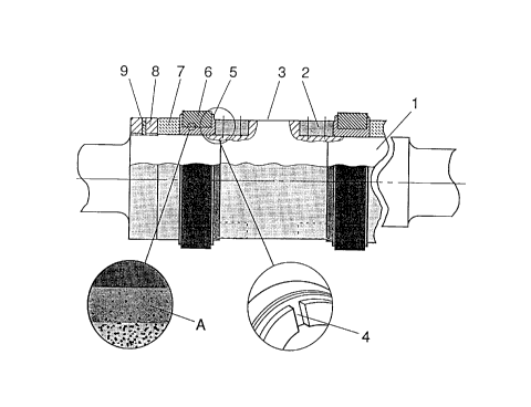
Figure 1 shows a roll structure where the torque is transmitted from
the spindle 1 via keys :?, fastened in the middle part 3 of the
spindle and fitting in t:he keyways 4 of the composite roll ring, to
the ductile iron part 5 of the composite roll ring and via the
metallurgical bond A to the carbide ring 6. The roll rings are
fixed via the sleeve 7 by the nut 8 with a locking screw 9.
CA 02005220 1999-02-12
6
Figure 2 shows a roll structure where the torque is
transmitted from the spindle lA via the key 2A to the sleeve
3A, whose driving lugs 4A fitting in the grooves 5A transmit
the torque to the ductile iron part 6A of the composite roll
ring and via the metallurgical bond A further to the carbide
ring 7A. The relative axial position of the roll rings is
determined by the sleeve 3A and is fixed via the sleeve 8A by
the nut 9A with a locking screw 10A.
Figure 3 shows a roll design where the torque is transmitted
from the spindle 1B via the key 2B in the keyway 3B to the
ductile iron part 4B of the composite roll ring and via the
metallurgical bond A further to the carbide ring 5B. The roll
rings are fixed via the sleeve 6B by the nut 7B with the
locking screw 8B.
Figure 4 shows a composite roll ring mounted on a free spindle
end i.e. the roll spindle has no bearing on one side of the
roll ring. The torque is transmitted by friction in the bore
of the roll ring, generated by the tapered sleeve 2C driven up
the taper part of the spindle 1C, to the ductile iron part 3C
of the composite roll ring and via the metallurgical bond A to
the carbide ring 4C.
Composite roll rings with carbide rings cast into ductile iron
have been tested in finishing and intermediate rod mills,
mounted on roll bodies with journals in both ends as well as
on free spindle ends. They have also been tested as rolls for
rolling reinforcement bars and tubes and as pinch rollers.
Their performance has been in good agreement with the
experience of carbide hot rolls gained since 1965. Carbide
rings in the diameter range of 100-500 mm, preferably 200-450
mm, and the drive by driving devices in the ductile iron open
up utilization also in bar mills. Carbide rings with
diameters up to 500 mm make possible utilization in cold
rolling mills and in other roll applications.
CA 02005220 1999-02-12
7
Example
A sintered cemented carbide ring with 70 % WC in a binder phase
consisting of 13 $ Co, 15 ~ Ni and 2 ~ Cr was blasted to clean its
surface from any adhering materials. The outer diameter of the ring
was 340 mm, the inner diameter 270 mm and its width 85 mm. A ring
of sand was formed around the carbide ring and it was then placed
in a bottom flask of a mould with suitable shape and dimensions and
provided with the necessary channels and an overflow box for the
molten iron. A ring of an exothermic material was placed in the top
flask of the mould and the two flasks were put together and firmly
locked.
Molten iron with a temperature of 1550°C and with a composition in
weight percent of 3,7 C, 2,3 Si, 0,3 Mn, 5,4 Ni, 0,2 Mo, 0,05
Mg, and balance Fe, was poured into the mould. In connection
herewith inoculants of ferro-silicium-magnesium was added, included
in the aforementioned analysis. The molten iron was poured into the
mould in such an amount and at such a flow rate, that a suitable
melting of the cemented carbide surface was obtained. When the iron
had risen to the exothermic material, it started to burn adding
heat to the iron. The mould cooled slowly to room temperature after
which the roll was removed from the mould, excessive iron cut off
and the roll cleaned. The quality of the bond and the absence of
flaws in the iron was checked by ultrasonic methods.
The roll was then heat treated to transform retained austenite to
bainite by heating to 900~C and keeping at that temperature for six
hours then lowering the temperature to 450°C and keeping there for
four hours before cooling to room temperature. Finally, the roll
was machined by turning to final shape and dimension viz. inner
diameter of the bore 255 mm and width 120 mm.