Note: Descriptions are shown in the official language in which they were submitted.
200s404
Background of the Invention
The invention relates to a process for allowing the
attachment of drive or coupling elements, such as cams, gears,
crank webs, or bearing elements, such as friction bearing
bushes or complete roller bearings, on tubes or tubular
portions, by hydraulic expansion of the tube in the region of
the respective element beyond the limit of elasticity against
an elastic prestress prevailing in the respective elements.
The hydraulic expansion is accomplished by means of a pressure
agent probe comprising effective portions which are associated
with the respective elements to be attached, which are limited
by seals and which, via a first probe borehole system, are
connected to a pressure agent generator. The pressure agent
probe also has intermediate portions between the individual
effective portions, which are in contact with a second probe
borehole system, and end portions adjoining the respective
outermost effective portions. The effective portions form
effective regions with the tube, the intermediate portions form
intermediate regions with the tube and the end portions form
end regions with the tube.
A pressure agent probe is known which comprises
two independent borehole systems the first of which, for
pressurizing the effective regions, is connected to a
pressure agent generator, and the second system, by being
connected to the intermediate portions, serves to drain
off any leakages, especially when some of the seals fail.
B'~
~ zoos~o~
The process which may be carried out with these means is
characterized by the pressure build-up in the effective regions
up to a point where the limit of elasticity of the tubular
portions concerned is exceeded, and the subsequent pressure
decreases. Accordingly, the pressure generator comprises an
exit which is directly connected to the first borehole system
of the pressure agent probe.
The essential problem of the prior art processes
relates to the lack of operating safety of the seals,
especially with increasingly larger shaft types to be produced
by this process the necessary pressures increase further.
Summary of the Invention
Accordingly, it is an object of the present invention
to provide a process which reduces the risk of seal failure and
improves the service life of the seals.
It is a further object of the invention to provide a
pressure agent probe suitable for carrying out the inventive
process, as well as a suitable pressure generator for carrying
out the process, which may be connected to such a probe.
Pursuant to this object, and others which will become
apparent hereafter, one aspect of present invention resides in
subjecting the effective regions to a high effective pressure
suitable for deforming the tube beyond its limit of elasticity.
ZOOS40~
The intermediate regions and the end regions, at least in the
portions on both sides of the effective regions and at least
while the high effective pressure is maintained, are subjected
to a lower counter pressure which is higher than the ambient
pressure and lower than the pressure required for deforming the
tube beyond its limit of elasticity. This process in
accordance with the invention allows considerably higher
effective pressures to be generated without having to modify
basically the type of seals used, as a rule standard annular
seals, since their failure and wear is primarily determined by
the pressure differential to be sealed, whereas they are
relative insensitive to an increase in the absolute pressure
level.
By generating, in accordance with the invention, a
counter pressure outside the effective regions which in no way,
permanently, adversely affects the properties of the tubular
member exposed in this region, the seals are prevented from
entering to an excessive extent the sealing gap, as a result of
which the service life of the seals is increased considerably
and simultaneously it becomes possible to increase the pressure
further. It is particularly important to apply the counter
pressure to the seals during the reduction in pressure after
the tube expansion, because during this phase there is a risk
of the seal being partially caught in the sealing gap and being
damaged mechanically while the member agent probe is pulled out
of the tubular member.
2005~04
When using a standard pressure agent generator which
builds up the pressure in an uncontrolled way, it is proposed
that, for the purpose of building up the pressure, a pre-
pressure which is lower than the effective pressure is
initially built up for sealing the seals in the effective
region. This is then followed by a further pressure build-up
in the effective regions and by a build-up of counter pressure
in the intermediate regions and end regions, with the pressure
in the effective regions always being higher than that in the
intermediate and end regions, until the required counter
pressure level has been achieved, with the pressure
differential having to remain below the design limit of the
seals. Thereafter, a further pressure build-up takes place in
the effective regions until the required effective pressure
level is reached, with the higher pressure in the effective
regions always ensuring contact of the seals. For the purpose
of reducing the pressure after building up and maintaining the
effective pressure, first, the pressure in the effective region
is reduced to an intermediate pressure level which is lower
than that of the counter pressure in order to relieve the load
on, and allow a spring-back of, the seals. Thereafter, the
pressure in the effective region and the counter pressure in
the intermediate and end regions are reduced jointly.
Depending on the design of the pressure agent probe,
the volumes of the intermediate and end regions connected to
the second borehole system are relatively large, so that in a
further advantageous embodiment of the process the spaces are
200540~
filled first with a low filling pressure whose level is below
that of the counter pressure. This presupposes the existence
of a pressure agent generator with suitable control facilities.
In a further embodiment, the process stage analogously applies
to filling the effective region prior to applying the effective
pressure. Depending on the behavior of the seals, the filling
pressure should be set in such a way that it moves the seals
into sealing contact with the tube so that during the
subsequent application of the effective and counter pressures
no uncontrolled deformation of the seals occurs.
The pressure reduction in the effective region on the
one hand and in the end and intermediate regions on the other
hand should preferably take place in a reverse sequence to that
of the pressure build-up, and again the objective has to be to
keep the pressure differentials at the seals as low as possible
and to achieve a seal release by means of a reversed pressure
differential.
In an another embodiment of the invention, the above-
mentioned filling pressure is applied even during the insertion
of the pressure agent probe and while the probe is pulled out
of the tubular member so that fluid flushes the seals at a low
pressure. This results in a desirable friction-reducing
lubricating effect for the seals relative to the rough inner
wall of the tubular member.
Z00540~
A pressure agent probe in accordance with the
invention for carrying out the above-mentioned process is
characterized in that outside the outer effective portions
limited by seals there are arranged, at a distance, further
seals for forming pressure-loaded end portions. The end
portions are connected to the same system of longitudinal
channels and radial boreholes connected thereto as the
intermediate portions and both borehole systems may be
separately connected to the pressure generating means. Such a
pressure agent probe makes it possible, as explained above, to
generate the required counter pressure in the intermediate and
end regions prior to, or while, applying the effective pressure
in the effective regions.
In a further embodiment of a pressure agent probe in
accordance with the invention the seal pairs of the effective
portions are framed on both sides by at least one counter
pressure portion limited by seals arranged in pairs. The
counter pressure portions are connected in pairs to the second
system of longitudinal channels and radial bores and both
borehole systems may be separately sealingly connected to
pressure agent means. In this way, in accordance with the
invention, each effective portion is associated with separate
adjoining portions to which a counter pressure is applied.
Depending on the probe design this arrangement may be
advantageous because it permits the volumes to be subjected to
the counter pressure to be kept very much smaller. The need
for a larger number of seals is thus reduced. This design is
2Q054~:)4
advantageous for probes with particularly pronounced sealing
portions with a larger diameter.
The above-mentioned basic probe designs may be
advantageously combined in such a way as to provide a third
borehole system of longitudinal channels and radial boreholes,
with the three existing systems then being subjected to
different pressure levels each, thereby permitting a double-
stage pressure differential for applying particularly high
pressures in the effective regions. The intermediate pressure
regions directly adjoining the effective regions may be kept
short enough for them to be still within the elements to be
attached, and the pressure acting within them deforms the tube
beyond its limit of elasticity.
Pressure generators in accordance with the invention
for carrying out the process in accordance with the invention
and for being connected to the pressure agent probes are
characterized in that one single working or pressure converting
piston, in the course of one operating stroke, loads at least
two pressure agent exits with different pressures. The working
piston especially being designed as a differential piston and
by connecting certain dead spaces the different pressure curves
required are generated.
The novel features which are considered as
characteristic for the invention are set forth in particular in
the appended claims. The invention itself, however, both as to
Z005~0~
its construction and its method of operation, together with
additional objects and advantages thereof, will be best
understood from the following description of specific
embodiments when read in connection with the accompanying
drawings.
Brief Description of the Drawing
Fig. 1 shows a longitudinal section and cross section
of a pressure agent probe pursuant to the present invention
with two borehole systems; and
Fig. 2 illustrates a longitudinal section and cross
section of a pressure agent probe pursuant to the present
invention with three borehole systems.
Detailed Description of Preferred Embodiments
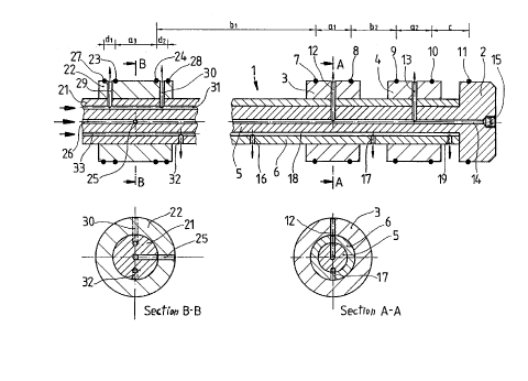
Fig. 1 shows a basic probe member 1 which ends in a
probe head 2 and onto which there have ben slid two sleeves 3,
4 which are connected to the basic member 1 by soldering, for
example. The basic member 1 consists of an inner tube 5
integral with the probe head and an outer tube 6. Seal pairs
7, 8 and 9, 10 define effective regions a1, a2 on the sleeves.
Between the effective regions there is an intermediate region
b. The probe head 2 is provided with a further seal 11 which,
together with the seal 10, defines an end region c. Via radial
boreholes 12, 13, the effective regions are connected to a
20054L0~
central pressure agent guiding borehole 14 in the basic probe
member 1 which penetrates the latter completely and is closed
in the probe head 2 by a plug 15. Via radial boreholes 16, 17,
the intermediate regions bl, b2 are connected to a longitudinal
channel 18 designed as a groove in the inner tube 5. Via a
further radial borehole 19 the end region c is connected to
this same longitudinal channel 18 whose end is closed by the
probe head 2. This second borehole system serves to build up
the counter pressure in all the intermediate regions b and the
end regions c.
In Fig. 2, a sleeve 22 has been slid onto a basic
probe member 21 in a way so as to be integral with it, which
sleeve 22 may be connected with the tubular member by gluing,
shrinking or soldering, for example. The sleeve 22 carries
seals 23, 24 which are arranged in pairs and define an
effective region a3. The effective region a3 is connected to a
central pressure agent channel 26 via a radial borehole 25
which extends vertically relative to the drawing. Further
seals 27, 28 directly adjoin the seals 23, 24 on the sleeve 22,
and define the above-mentioned counter or intermediate pressure
portions dl, d2. Via radial boreholes 29, 30, the intermediate
pressure portions dl, d2 are connected to a longitudinal
channel 31 in the basic probe member 21 via which a counter
pressure has to be applied if no further boreholes have been
provided in the probe. An intermediate pressure is applied if
the probe has a third system of radial boreholes 32 which, via
2005~0~
a third longitudinal channel 33 are loaded with a counter
pressure for the intermediate and end regions.
While the invention has been illustrated and
described as embodied in a process for allowing attachment of
elements on tubes, it is not intended to be limited to the
details shown, since various modifications and structural
changes may be made without departing in any way from the
spirit of the present invention.
Without further analysis, the foregoing will so fully
reveal the gist of the present invention that others can, by
applying current knowledge, readily adapt it for various
applications without omitting features that, from the
standpoint of prior art, fairly constitute essential
characteristics of the generic or specific aspects of this
invention.
What is claimed as new and desired to be protected by
letters patent is set forth in the appended claims.