Note: Descriptions are shown in the official language in which they were submitted.
33
EXPULSION PROJECTILE
.
5 Technical Field
This invention relates to an expulsion
projectile, and more particularly a projectile for
training purposes where a full explosive effect, as
required in combat situations, is not required, but
10 detonation of a quantity of pyrotechnic is required to
provide personnel with an indication of the results of
firing of the projectile during training. The projectile
may also be utilized to release items other than
quantities of pyrotechnic, such as canisters containing
15 flares or explosive devices which are required to be .
distributed.
',
:
' ,- '
... - . ": ~ . . .. . . ~
Z~ 33
Background Art
In practice, the firing of a training
projectile from a gun, cannon or like launching device or
weapon, involves the use of a round of ammunition
5 consisting of a cartridge case containing a propellant
and also the projectile itself which are loaded in to the
breach of the weapon, the projectile being loaded first
followed by the cartridge case, and which upon firing
ignites the propellant in the cartridge case to launch
10 the projectile towards the desir~d target. With
expulsion projectiles for training purposes, a canister ;~ ;`
of pyrotechnic (or high explosive) is contained within a
cavity in the rear of the projectile, and together with a
fuze, is held in place by a closure assembly for the
15 cavity. The closure assembly must be sufficiently strong ~-
as to not rupture inwardly under the force exerted by the
propellant gases in the cartridge case, but also `
sufficiently weak to rupture outwardly when the
pyrotechnic spotting package in the projectile either
20 functions or is ejected and the products of combustion of
the pyrotechnic in the form of light (flame) and smoke
provide an indication to personnel during training.
Nith one form of known expulsion projectile the
closure assembly consists of a plug screw-threaded into
25 the rear end of the projectile to close the cavity
containing the pyrotechnic and the fuze or other
payloads, but the force created by functioning of an
expulsion charge or the detonation of the pyrotechnic has i~
to be sufficient to shear the threads of the
30 screw-threaded plug and in order to do so, the ejection ;
force must be relatively large.
Disclosure of the Invention
It is therefore an object of the present
invention to provide a projectile, the rear closure ; ;
35 assembly or base of which can withstand the externally '~
2~~15~3~
- 3 -
:
applied forces applied to the projectile when the round
is fired, but which can be relatively easily rearwardly
released from connection to the projectile using a
minimum ejection force.
The invention therefor envisages a pxojectile
having a housing containing a rear cavity for the receipt
of a canister to be rearwardly ejected after firing of
the projectile, said rear cavity being closed by a
closure assembly, said closure assembly including an
10 inner substantially rigid base member and an outer
relatively thin retaining plate holding the base member
in position and, in turn, held in position by a radially
inwardly directed~retaining means carried by the
projectile housing and overlying a peripheral edge
15 portion of the retaining plate.
During firing of the projectile, the external
forces applied after deflagration of the propellant in
the cartridge case are borne by the combination of the
rigid base member and the retaining plate, whilst upon
20 functioning of an expulsion charge or detonation of the
pyrotechnic after impact with a target, or upon
functioning of a time delay fuze in the cavity, the
closure assembly is rearwardly ejected as the retaining
plate bulges outwardly whereby its peripheral edge
25 portion moves radially inwardly to escape the confines of
the retaining means.
Preferably said retaining means is a flange
formed integrally with the projectile housing - -
Preferably the diameter of the base member is
30 less than that of the retaining plate whereby the forces
applied by its peripheral edge to the retaining plate are
radially inwardly of the periphery of the retaining plate
to provide a mechanical advantage such that the retaining
plate more readily bulges outwardly to release its
. - : , : .. . . ..
.
,:, : - ~ . , . .:
- ,
: - :
. . . : . . . . .
. - . .: .:
~S4~33
peripheral edge portion from the confines of the radially -
inwardly directed flan~e of the projectile housing -
without any plastic deformation of the plate.
Brief Description of the Drawings
. . . _ _ . . _ .
One preferred embodiment of the invention will
now be described with reference to the accompanying
drawings, in which:
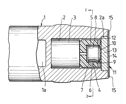
Figure 1 is a cross-sectional view through the
rear portion of a projectile in accordance with the ~ ;
10 preferred embodiment of the present invention; and -
Figure 2 is a cross-sectional view taken along
line 2~2 of Figure 1.
::
Best Mode for Carrying Out the Invention
In this preferred embodiment of the invention,
15 the projectile comprises a generally cylindrical housing
1 tapering forwardly (not shown) to an inert tip or nose,
and also tapering rearwardly as shown, to its rear end or
base. The forward end of the projectile contains an
elongate cylindrical cavity la, the forward end of which
20 is closed by à conical tip member (not shown). -
The rear end of the projectile contains a rear
cylindrical cavity 2 in which is inserted a thin walled
aluminium canister 3 containing a pyrotechnic (or high
explosive), followed by a cylindrical nylon holder 4 ~ -
25 bearing against the end of the canister 3 and which, in -
turn, has a reax cylindrical cavity 5 which receives a
fuze 8. The orientation of the fuze is correctly aligned
by means of an alignment pin 6 extending radially
inwardly of the holder 4 to engage within a slot 7
30 extending longitudinally of the fuze 8. The holder 4 is,
in turn, held in place via an annular spacer 9 and
disc-shaped felt pad 10 to allow for any dimensional
tolerances, and the whole assembly is completed by a
closure assembly generally indicated as 11.
.,`
2Q~5~3
.,,
The rear cavity 2 is stepped as 12 to provide a
larger diameter portion ~a at the opening from the cavity
2, and the closure assembly 11 comprises a rigid steel,
disc-shaped base member 13 bearing against the ~elt pad
5 10 and slidably received within the larger diameter
portion 2a of the cavity 2. The closure assembly 11 is
completed by a thin outer aluminium retaining plate 14,
the circumferential peripheral portion of which is held
in place by a radially inwardly directed circumferential
10 flange 15 forming part of the rear end of the housing 1
o the projectile.
In the embodiment described, upon launching of
the projectile frQm the weapon by means of deflagration
of the propellant in the associated cartridge case as
15 previously described, the external forces applied to the
rear or base of the projectile are borne by the closure - :
assembly 11, and in particular the rigid base member 13,
so as to prevent actuation of the fuze 8 and premature
detonation of the pyrotechnic in the canister 3.
20 However, upon impact of the projectile with the target
the impact forces will cause actuation of the fuze 8 and -
detonation of the pyrotechnic within the canister 3
causing an expansion of the products of combustion of the ~ .
pyrotechnic within the rear cavity 2 to act on the
25 assembly of holder 4, spacer 9, pad 10 and closure
assembly 11 and cause the assembly to be rearwardly
ejected from the projectile with the combusting
pyrotechnic resulting in the production of light (flame)
and sound to indicate to personnel the point of impact of
30 the projectile with the target. In order to eject the
rear assembly, all that is required is that the retaining
plate 14 disengage from within the inwardly directed
flange 15 of the projectile housing, and this is merely
achieved by the base member being rearwardly forced
35 against a retaining plate to cause it to bulge outwardly
whereby its peripheral portion moves radially inwardly
ZQ~ 33
- 6 -
without any plastic deformation and its diameter decreaseto a size less than the internal diameter defined by the
flange 15. It will be apparent that the internal force
required by detonation of the pyrotechnic is considerably
5 less than the external force required during deflagration
of the propellant in the associat:ed cartridge case to
launch the projectile, and thus c:onsiderably less
ejection force is required than is the case with known . :
projectiles. In addition, as the diameter of the base :.
10 member 13 is less than the diameter of the retaining
plate 14, the mechanical advantage achieved by the
peripheral edge of the base member being applied radially :
inwardly of the p~ripheral edge of the retaining plate :
14, reduces the force required to bulge the retaining
15 plate and disengage its peripheral edge portion from the
confines of the flange 15 of the projectile housin~
As an alternative to utilizing the projectile : :
in a training exercise, it may also be used to rearwardly :~
eject other items such as canisters or clusters of other ; .~.
20 military items such as flares to illuminate the :
surrounding area, or explosive devices to be distributed :~
over a predetermined ground area, and in that respect the ;~
rear cavity may contain a quantity of propellant material `:`~
adapted to be ignited by a fuze having a pre-selected :.-~
25 time delay function to achieve rear ejection of the items ;;.
in question at a predetermined point in the flight of the . :
projectile. ~ :`