Note: Descriptions are shown in the official language in which they were submitted.
~ Q ~5~
ACKGE~O~N~ OF THE_I VENTION
~he present invenkion r~lat~s to a sawln~ ~auge system to
be u e~ in c2se of ~nteL-trochantery accommod~tion
osteotomies .
The large spongeous bone area availa~le ~uring
intertrochantexy ~co~od~ion os~eotomies would su~est
that a ~ood reforma-tlom of the bon~ $~cture c~n be
achieved. It ~till, however, c~n occ~r that the bone only
heal~ sl~wly due to bo~e reabsorptio~ in the osteotom~
o -area. The ~one rea~sorption takes place as a result o~
mi~romo~e~ents on the contac~ s~xfac~ and si~nalizes an
lnsufficient lnter~ragment~ry ~ompre~slon.
~h~ compression of th~ bone fragmen~s is u~ually carried
out with an ~ngle pla~e aid~d bv a plate ~lamp or
acco~ding to ~he slotted ~lide pl~t.e principle. These
~ethods cause ~he later~l ~or~ic~l to be Gompressed 2S the
pla~e is excen~r~cally si~uated. The medial cor~ical is,
on the other. hand, under te~sion~ In gener~l, the
principl~ of overben~ng of the plat~ ~s not ta~en into
consideration. ~t i~ therefo~e z tension ~hord
Qs~eo~iynthesis,
'
ZOO~
The~e ~re numorous lite.rature references as to hor~
interfr~gmen~ary colnpression can be ~chieved ~urln~
~ntertroch~7~tery oste~tomy. Following the me~hod accordi7,~g
to ~uchner, th~ compression is achieved whils~ the plate
is being struck in due ~o an ~7,~reasing dist~nce bet-~een
the ra~or socket and the osteotomy ~ea. The renewed
strtking o~ the pl~te previously fixed in rel~tion to the
dlst2~ pre~surizes the osteotomy a~e~. ~n t~ls oonnection,
reference ls ~ade to an article in the ~o~rna~
"Orthop~ie" No. 112 by ~ uss, pu~lished in ~974,
p~ges ~43-~50. In another re~erence, "~ie intertro~hantere
os~eotomi~ bei Cox~rt~ose" ~Inter~rochatery osteotomy 'oy
coxarth~osis) by ~. SchQelde~ publisned in 1979 by
Springer-~erl~g, B~rlin, the author ~eco~mends inclined
osteotomy areas ~hich then becom compre~sed by s~re~7ing
the proxim~l serew, In ~othe~ refe~en~e, an ~rticle in
the journal "Orthop~dlQ" No. 1~2, publ~shed in 1384, pag~s
705-715, Hei~el sugg~sts that the prin~iple of overbenAlng
of the plate ~c~ordlng ~o B~g~y ~e ta~e~ ln~o
considera~ion in order to prevent the osteotomy f~om
spli~-ting open on the m~dial side. sagby descrihes the
overbendln~ o~ the p~ate in the case sf shaft fra~tures.
All thes~ methods have the disadvantage, th~t their
effectiveness ~a~ot be asse~sed a~uratel~ and that some
c~n caus~ considerable shear s~r~sslng.
S~
SUMMARY O~ THE INVENTION
I~ is an ob;ect of the invention ~o provide a device
which can remo~e a wedge-shape section o~ bone with a
predet~rmined wedge-angle so that an optlmal
prestress load ~ c~n act.
The ob~ect an~ others to beGo~e apparent as the
specifi~at~an p~o~re ses, a~e acco~plished ~y the
invention, ~ccording to which~ briefl~ st~ted, the sawing
gaug~ sys~e~ ~o be used in case of l~te~rochantery
lo ~ccommodatlon osteotomies includes a first sawing gauge
having ~n underside curved like a hollow cylinder for a
face-to-face engagement ~ith the bone surface of the femur
shaft and a sawing openin~ oriente~ vertical to the axis
of the fe~u~ shaft, and a second sawing gauge haYin~ an
underside being cux~ed like a hollo~ cy~inder for a
~ac~-to-~ace engagement with the bone sur~ac~ of the ~e~r
sha~t and a sawing op~nin~ in~lined towards ~he sawing
opening in the fixst sawing gauge by ~n angle of ~o if the
axe~ of the undersides of the first and se~ond sawing
~u~e~ ~o~
The sawing gau~e ~ystem ~ccordiny to the lnventien
consist~ o~ ~wo seperate sawtng g~uges enab~ing two cuts
to be ca~ried out quickly and accurately. The first cut is
made vertical to the shaft a~is in the proxi~al f~ur and
the~ the second cut is made at an ~n~le, in particular a
~ ~.gle, t~ the first cu~, the secon~ cut interseeting
the ~irst cut. The second sawing gauge can be positioned
exactl~ in rel~lon to the position of the first cut.
J~
~he optimal reformation of the osteotomy re~uires an
optlmal interfrag~entar~ pressure distribution. This ~oal
can be achleved by preci~ely ~efinlng ~nd there~ore
qua~ ing an ~ngle a ln ~egrees so that ~n e~act open~ng
in the lateral direc~-io~ of the osteoto~y su~f2ces is
de~ined. The wedge-~hape se~tion of bone which h~s to be
removed for ~orrectlon is dime~sioned in such a way th~t
the opening in the late~al directlon remains open after
correction and prio~ to the pres~ressing. This means that
lo the removed varlsation wedge is small~r by ~ and the
v~l~isation wedge ls ~reater ~y a. ~n this way the medic~l
corticalis ls the ~irst to be pr~ssurized at the beglnnlng
of the p~estresslng with load F. By utillsing the elasti~
and biomechanic~l proper~ies of the angle-plate the
proximal fra~ment tllts about a pivot in the medial
corticalis as the. prBstresslng continueB and does so until
t~e openin~ is close~ ~nd an even medial and l~teral
co~pre~sion h~s been xeached. This movement pxevents shear
stress from taking place.
The results of exp~iments show th~t not only when re~ted,
but al~o ~hen static loadlng læ si~ulated, an even
interfragmentary compression distribution ca~ be obtained
during intertxochantery accomo~ation osteotomities if the
osteoto~y areas are opened at an an~le of a = ~ prior to
prestressin~ with a ~oad ~ = 1000 N. The priciple of
tenslon chord osteosynthesis ls op~imated by the principle
o~ compressional osteosynthesis. ~ensional s~resses and
stress peaks which resul~ in the pathologlcal reduction of
bone mate~ial ~ reduced. Relative movements can be
avoided.
Z~
The angl~ of a 6 ca~ b~ u~problema~ically implemented
usin~ two sawing g~uges durlng a~ operation.~he bone is
precisely ~ut verti~al to the dlstal fra~ment wlth ~he
first sawing gauye. Then the pl~te-posltionlng inæt~ument
is struck into the thigh shaft at an angle which is 6
smaller than the ~ctual angle required for the corre~tion
due to ~he pla~e bending upwards dux~ng ~he prestressing
i.e it v21~a~ises. ~fter ths angle~plate has been
positioned a second saw gauge ~s attache~ to th~
lo plate-shaft. ~hls makes it pos~ible ~o remove a corLection
wedge fro~ the proxlmal ~ragment whilst at the ~am8 time
taking the angle a - 6 lnto ~onsideration. The sawin~
direction runs ver~ically to ~he plate-shaft mimls 6~. In
that way a lateral openin~ of the osteotom~ ar~as of 6
~emains. The plate is then flrmly fixed to the thigh sh~f~
by ~ sc~ew through the uppermost slot and is tightened
with a plate tig~tener. The flnal ~tages of the assembly
are the usual ones.
The sawing ~auges have concave curved understdes and these
~uarantee that they can be exactly fi~ted to the femur
shaft. Met~l pi~s whi~h dig into the periost and/or
Randels~hrauben shaped as set-scxews are used to prevent
~ovement.
The l~nyth of the contact surface axea ~nd in particular
t~at of the fir~t sawlng yauge ls limited by the size of
the opera~iv~ ~ou~d. x~ 1s nevertheless large enough for
the parallel assembly 1I the length of the contact surface
~rea i~ long~ than the length of the ~ut to be sawed. The
first sawing gauge is manually held w~th a grip.
~t~
he second sawing ~auge is pushed onto the shaft of the
angle-plate with a sllde part and locked in the preferred
embodiment wlth a (Randelschraube) ~te~ the angle-plate
has ~een mounted. A sawlng block wl~h a sawing open~ng is
connec~ed ~o a longltudinally adjustable and p~eferably
lockable part wh~ch is conn~cted to the slide part by
bein~ attached to a knee part. The dlrecllon of movemznt
o~ the slide p~t and the longitudinally adjustable part
are ver~ically on to~ of one anoth~r. This ~eans that the
o second sawin~ gauge can b~ ~xactly positioned in front of
the cut made ~y the first sawing gaugs. The knee part
~etween the height adjustabl~ part and the sawing block
leads to the contact surface are~ o~ the second sawing
~uge with the femu~ sha~t bel~g turned e~actly ~0 away
from the cont~ct surface a~ea of the angle-plate shaf~.
The sawi~g direction is, in accord~nce wlth the sawing
opening, cut lnto the s~win~ block gob _ 6 - 8~ from the
femur shaft, so ~hat a correct1on ~edge can be removed
~om ths proximal frag~en~ an~ a lateral openiny o~ the
osteoto~y areas of 6 remain~.
~he utilisation o~ the sawing gauge syst~m according to
the in~ention leads ~o less forming of pseudarth~osis and
les slowhr heal~ng of ~he bone as wsll as ~reater safety
~l~h regard to post operatl~e ~xerciseQ and mo~ilisation
of the patien~ as this is a strong osteosynthesis.
~ Q ~
BRIE~ ~ESCRIPTION o~ THE DRAWINGS
Fi~ure la is a schematic side elevational view of
prefsrred embodiment of the first sawing gauge.
Figure lb ls 2 view of the un~e~side to be placed on the
femur sha~t of ~he firs~ sawing g~uge accordlng to
Figure la.
Figure lc ls a front eleva~ion of the first saw gauge
according to Figu~e la.
Figure ld ls a pe~spective view of the first saw gauge
according to Figures la to lc.
Fi~ure 2a is a schema~lc side elev~tlonal view of a
prefe~red embodiment o~ the se~ond sawing gau~e.
Fi~ure 2b is ~ plan elevation o~ ~he second sawing gau~e
: a~cordin~ to Fl~ure 2a.
~igure 2c is a fro~t ~evation o~ ~he seoond saw gauge
ac~ordl~g to ~i~ure 2a.
Figure 2d ls a perspectlv0 view of the second saw gauge
~ccordlng to ~igu~es ~a to 2c.
Figure 3a shows ~he os~eotomy angle prior to compression.
2~
Fi~ure 3b shows the inter~ragmentary compression
d~stribution in the case of a osteotomi~al angle of 6.
DESCRTPT~VN OF THE PR~ERRE~ EMBODIMENT
The experlmentally determlne~ aptim~l wedge angle of
a ~ 60 ~an be ~et e~sily du~ing an operation with two
sawin~ gau~es ~hat are installed one 2~ter the other. The
~emur is cut exactly verti~ally to lts shaft a~ls wi~h the
first sawlng gauge. Th~ pre~erred embodiment o~ the first
sawing g~uger ~s illustrated in di~fe~2nt ~iews in the
o ~l~ur~s la to 1~, conslsts o~ a s~wing blocX 1 with a
s~wing opening 2, a support 3 and a handle 4, whe~eby the
sawing openi~y ~ ls e~actly vertic31 to the longi~udinal
dire~tion o~ suppo~t 3 which implies that it is, in turn,
cut into the ~awin~ block 1 ve~tlcal to the shaft ~xis.
The suppo~t 3 is curved on l~s unde~side in the form of a
hoLlow cylin~er and is therore simllar in sh~pe to that
o~ the bone. In order ~o ensure that the support ~ is
protec~e~ against non-intentional movements along the hone
su~ace when leanin~ against the bone the support is
evenly covered wi~h metal pins 6 on the underside 5 which
dig into the periost. ThP. support 3 supports the sawing
block 1 and th~ ~awin~ openlng 2. ~he h~ndle 4 which is
mounted on ~he ~pp~r side of ~he suppo~t 3 ~nables the
~irst saw~n~ block to be held manually to prevent sliding
during the ~wlng process.
J ~I it
~fter the ~one has been separated, whereby the sawing
opening 2 acts a~ a stencil, the flrs~ sawing gauge is
removed and a plat~-positionin~ instrument ls ~truck into
the thigh shaf~ ~t an angle which ~s 6 smaller than the
actual an~le required for the correction ~ecause - a~ can
be seen ~om the ~igures 3~ ana 3b - an angle plate 7 yet
to be positioned bend~ up by ~o during the prest~essing.
A second sawing gau~e is attached to the plate-sh~ft 8 of
the angl~-plate 7 aft~r lt has been pO5 1 tioned.
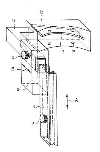
o The pre~erred embodiment o~ the second sawing gauge, as
illustr~ted in different views in the Figures 2a to 2d, is
needed to remove the wedge-shape sectlon of bone with a
wedge-angl~ of ~. The second sawlng gauge differs from
the first s~wing ~auge in the way that it is positioned
and the poslt~on of it~ s~win~ openin~. The second sawing
gaug~ consi~ts of a ~lide p~rt 9, which can be pushed onto
the angle plate shaft 8 ( as illus~rated dashed in Figure
2c) of the angle plate 7 in the direction of ~rro~ A, a
longitudinally, ln the direction of arrow ~ adjustable
part lo, a kne~ part 11 and a sawlng hlock 12 wlth a
sawin~ opening 13 situat~d at an angle~ The underside 14
of the sawing block 12, ~hich 1~ to lean aginst the bo~e
surface, is formed like a hollow cylinder and is covered
with a numb~ of me~al pin~ 15 to ~ug~ent the adhesion.
2~
The slide part 9 i~ connected t~ the longltudinally
ad~ustable part 10 in sUch a way that they can be moved
vertically relative to each o~her and also that the sllde
part 9 c~n be moved vertically relatlve to the first
osteotomy cut made by ths first saw~ng g~uge. The
right-angled knee part 11 is co~ect~d to the
longitudi~ally ad~ust~ble part 10 ~nd ths sawing block 12.
AS the sa~lng blo~ 12 ls comlected to the knee part 11 it
can be ~owered to re~t on the bone b~ moving the
lo longitudinally ad~ustable part 10 and can be moved
l~ter~l~y by mo~ing ths slide part 9 ~long the
plate-shaft 8 o~ ths angle-plate 7 until the sa~ing
opening 13 o~ the sawing block 1~ ls exactly lined up with
the exlsting oste~tomy cut. Th~ relative pos~tioning o~
the clide part 9 and the pla~e-sh~ft 8 is fixed with a
gerandel~e set-screw 16. Another geY~ndelte set~screw 17
is use~ to fi~ the longitudinally adjus~able part 10 to
the knee pa~t 11.
The corre~tion wed~e i~ ~emoved from the proximal
fra~ment. Th~ ~awi~ diroction is at an angle of
90 ~ 6 = 84~ to the angle plate-shaft ~. A later~l
opening of the osteoto~y ~reas o~ 6~ remains.
'The F~gu~es 3a and 3b illu~trate the ef~ect of compression
on the ~issure 1~ ~ut i~to t~e femur 18 using the sawing
gauges according to the invention. The angle-plate 7 and
the pla~e shaft 8 are fl~ed wlth a sc~ew through the upper
2~00 D'~
(not shown) slot. Usln~ an ordinary plate tigh~ener (also
not shown) the bones are then transferred ~rom the
positlon as lllustr~ted in ~lgure 3~ wi~h the open fissure
to ~h~ position as illustrated in Figure 3b with the
closed fissuro. The pre~tressing load is approximately
1000 N. The ~in~l stages of fixation are the usual ones.
The stressing device is not part of the ~nvention.
Figures 3a and 3b are only meant to show the surgical
method used when utilising the sawing g~uges according to
o this invention in o~der to be able to clarify thelr
functlon .
It will be understood that the above description of the
~resent invention is ~usceptible to various modiPications,
changes and adaptations, and the ~ame are i~tendsd to be
comprehended within t~e meaning and ~ange of egui~alents
of the appended claims.