Note: Descriptions are shown in the official language in which they were submitted.
2005607
-- 1 --
METHOD OF ANALYZING GUIDED OPTICS COMPONENTS, OPTICAL
FIBRES OR OPTICAL GUIDE NETWORKS BY TIME REFLECTOMETRY AND
REFLECTOMETER IN THE TIME SPHERE.
Optical reflectometry in the time sphere makes it
possible to analyse guided optics components, optical
fibres or optical guide networks. It is for example used
for evaluating insertion losses of connectors and losses
at the splices, determining fibre section lengths,
localizing and identifying defects and evaluating the
attenuation per unit length.
According to its traditional principle, a light
pulse called probe pulse is injected into an optical guide
connected to the system which it is desired to analyse.
During its propagation, a small part of the optical power
of this pulse is backscattered by the refraction index
inhomogeneities of the system to be analyzed, by its
defects and by the dioptres it meets, by joints and
connecting components (connectors, couplers,
attenuators...).
The backscattered response signal constitutes a
signature of the system and comprises characteristics of
all its elements.
It is received by a photodetector and it is the
corresponding electric signal, delivered by a detection-
amplification block which is processed and displayed.
Representation of the signal from the detection-
amplification and processing operations will be designated
by "backscatter trace".
The quality of the reflectometer used in this method
depends both on its measurement dynamics and its
resolution power.
Resolution is the capacity of the reflectometer to
dissociate the contribution to the backscattered signal of
the defects, dioptres or components close to one another.
It is all the better the shorter the duration of the probe
200S607
pulses and the wider the detection-amplification passband.
The dynamics, expressed in decibels, is the ~ax;mum
value of the signal to noise ratio recorded at the
beginning of the backscatter trace. It is all the higher
the more the probe pulses are energetic (so of long
duration) and the narrower the passband of the detection-
amplification unit.
For a given system, the length capable of being
analyzed by a reflectometer (range) increases with the
dynamics thereof.
High dynamics and high resolution requirements are
apparently contradictory and have led up to present to a
compromise between these two qualities. Some of the known
apparatus privilege the dynamics to the detriment of the
resolution whereas others prefer to offer a better
resolution with lower dynamics.
The purpose of the present invention is to provide a
method of analyzing guided optics components, optical
fibres or optical guide networks by time reflectometry
offering simultaneously high dynamics and high resolution.
It is also an object of the present invention to
provide a reflectometer for implementing this method.
It is an important contribution of the invention not
to have accepted the generally admitted limitation and to
have proposed means for overcoming it.
For this, the method of analyzing guided optics
components, optical fibres or optical guide networks by
reflectometry in the time sphere of the invention is of
the type in which a light probe signal formed of short
periodic pulses is fed into a guide connected to the
system to be analyzed, and the backscattered response
signal is analyzed. It is characterized in that the
backscattered response signal is sampled by interaction
with the light signal called pump signal, formed of short
periodic pulses so as to produce a new signal called
sampled signal received by a photodetector which is blind
200S607
._
to the pump signal and to the backscattered response
signal. The repetition frequency of the pulses of the pump
signal is close to that of the pulses of the probe signal
or close to a multiple or a sub-multiple of this
frequency. The backscattered response signal is recomposed
from signal samples delivered by the photodetector.
The reflectometer in the time sphere for analyzing
guided optics components, optical fibres or optical guide
networks is of the type comprising means for transmitting
a probe light signal formed of short periodic pulses, a
light flow separating device for injecting the probe
signal into a guide connected to the system to be analyzed
and extracting the backscattered response signal and means
for analyzing the backscattered response signal.
According to the invention, the means for analyzing
the backscattered response signal comprise means for
producing a light pump wave formed of short periodic
pulses, the repetition frequency of these pulses being
close to the repetition frequency of the probe signal or
close to a multiple or a sub-multiple of this frequency,
means for causing the pump signal to interact with the
backscattered response signal so as to provide optical
sampling of the backscattered response signal and produce
a sampled light signal, a photodetector receiving the
sampled light signal and insensitive to the pump signal
and to the backscattered response signal, and an electric
unit processing and storing the photodetected samples and
recomposing the backscattered response signal.
The invention will be described in greater detail
hereafter with reference to the figures in which :
Figure 1 shows a backscatter trace,
Figure 2 is a general diagram of the method of the
invention,
Figure 3 shows the reflectometer of the invention,
and
Figure 4 is a general explanatory diagram of the
`_ ~005607
method of the invention.
The backscatter trace shown in Figure 1 comprises
one or more peaks 1 to 3 generated by the probe signal 11
during its propagation through the system 8.
Between these peaks 1 to 3, the decrease of the
trace in zone 4 depends on the attenuation per unit length
of the fibre.
The noise of the detection-amplification unit is
shown at 6.
Peak 1 is produced by the reflection of the probe
pulse 11 at the input to the system 8. The signal to noise
ratio at point 5 at the foot of peak 1 indicates the
dynamics of the reflectometer.
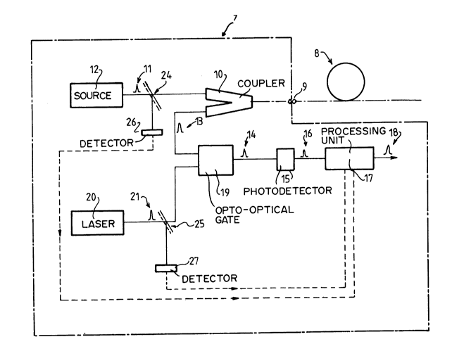
Reflectometer 7 is intended to analyse the assembly
8 which is formed of any assembly of guided optics
elements. Very often it is an assembly of fibres, optical
guide networks and different components, connectors,
couplers, attenuators...
Such an assembly may be an element of an optical
fibre telecommunications network.
Connection of reflectometer 1 to the assembly 8 is
provided by connector 9. A Y coupler 10 feeds a light
signal 11 emitted by source 12 into assembly 8 and
extracts the backscattered signal 13.
Traditionally, this backscattered signal is detected
directly then amplified, sampled electronically, processed
in order to increase the signal to noise ratio and
displayed.
On the contrary, in accordance with the invention,
this backscattered signal 13 is sampled optically so as to
produce a light signal 14 which is itself transformed by
photodetector 15 into an electric signal 16. The
processing unit 17 then recomposes an electric signal 18
corresponding to the backscattered optical signal 13. This
signal 18 is then either displayed or used directly for
any desired subsequent processing.
. ~
- 2005607
Sampling is provided by an opto-optical gate system
19 controlled by a laser or by a laser diode 20 producing
pulses 21. The opto-optical gate 19 comprises a linear
crystal 22 and laser 20 emits light pulses 21 forming a
periodic pump signal whose repetition frequency is close
to that of the pulses of the probe signal 11 or close to a
multiple or a sub-multiple of this frequency.
The effect of the probe signal 14 on the optical
guide system 8 is to produce backscattered optical signals
13. Each of these signals has a duration appreciably
greater than that of a pulse of the probe signal 11. The
form of these signals depends on the nature of the
elements producing the backscatter. The opto-optical gate
19 produces a sampled optical signal 14 which is received
by the photodetector 15. Each of signals 14 is deformed by
the transfer function of detector 15 and so is appreciably
widened. However, the electronic processing of this signal
provided by the processing unit 19 makes it possible to
overcome such widening and to reconstitute an electric
signal which is substantially homothetic of the optical
signal 13. For this, the processing unit 17 may for
example assign to each pulse a value which depends on the
energy of the corresponding pulse 16.
The method of the invention is independent of the
transfer function of detector 15 and a detection-
amplification unit having a small passband may be used.
It is sufficient for the passband to be the inverse
of the recurrence period of the pump pulses 11 and so very
much less than that required by prior art methods which
must be of the order of the inverse of the duration of the
probe pulses. In fact, the resolution of the reflectometer
is no longer set by the passband of the detection-
amplification unit but by the performances of the opto-
optical gate which uses ultra-rapid non linear optics
phenomena.
According to the invention, the very high rate of
.~
200560~7
extinction of gate 15, combined with the low value of the
passband of the detection-amplification unit, leads to
much greater dynamics than that permitted by the prior art
devices and methods, without having to compromise on the
resolution power.
Sources 12 and 20 are also capable of delivering
brief and coherent light pulses. They are preferably
lasers or laser diodes.
The laser diodes for providing the probe pulses
preferably emit signals at wavelengths of 0.85 microns,
1.3 microns or 1.55 microns which are the wavelengths
usually for optical fibres.
Different types of opto-optical gates may be used,
preferably a non linear crystal of order 2 will be used,
for example a KDP crystal which provides a non colinear
parametric frequency conversion. In order to improve the
signal to noise ratio and avoid possible parasite signals,
the photodetector, which is of course sensitive to the
frequency generated by the crystal, is made insensitive
both to the backscattered response signal and to the pump
signal. For this, the photodetector is preceded by a
chromatic filter 28 or a spatial filter 29 or
simultaneously by both.
If Tl is the time separating two probe signal pulses
11, the repetition frequency fl of the probe source 12 is
defined by fl = l/Tl. Similarly, if T2 is the time
separating two pulses of the pump signal 21, the
repetition frequency f2 of the pump laser 20 is defined by
f2 = 1/T2. f2 is chosen so that f2 = kfl + f, k being an
integer or the inverse of an integer. Then Tl = kT2 + T.
This makes it possible to obtain a resolution related to
T, since two successive samples deliver information
concerning two points of the fibre spaced apart by c/Nl T.
c represents the speed of light in a vacuum and Nl the
group index of the fibre.
In a preferred embodiment, an optical amplifier 23
200560'7
is inserted between the optical coupler 10 and the opto-
optical gate 19 which permits the use of low levels of the
backscattered signal 13.
Fluctuations of the level either of the probe signal
11 or of the pump signal 21 may produce undesirable
effects on the backscattered sampled light signal 13.
These effects may be offset at the level of the electronic
processing unit from the previous acquisition of the level
of the transmitted signal 11 and that of the pump signal
21. For that, separators 24, 25 are placed a the output of
sources 12 and 20 for taking off a small part of the
transmitted signals. The rear signals of sources 12 and 20
may also be used, when these sources are lasers. The
signals thus taken are fed to detectors 26, 27 which
deliver to the processing unit 17 electric signals
characteristic of the power of the probe and pump pulses
respectively.
In some special configurations, for acquisition of
isolated samples, the repetition frequency of the pump
pulses will be made equal to that of the pulses of the
probe signal, or equal to a whole multiple of this
frequency.
When the sampled signal 14 has a low power level, it
is increased by inserting an optical amplifier 23 either
between coupler 10 and sampler 19,20 or after sampler
19,20 and before the detector 15.
The use of an opto-optical sampler 19,20 then makes
it possible to analyse recurrent optical signals 13 even
if they are formed of brief low power pulses with high
dynamics and high resolution, while overcoming the
constraints imposed by the pulsed response of the
detection-amplification unit 15.
Z005607
Although the invention has been described above in
relation to one specific form, it will be evident that
it may be refined and modified in various ways.
Furthermore, it should be understood that system 8 is
any optical network composed of guided optics
components, optical fibres, optical guided networks.
Reflectometer in time sphere are words used to make out
the difference between the kind of reflectometer used
in time reflectometry (light pulses are injected in the
system to be analysed and -almost among other
parameters- time between the emission of these pulses
and the reception of backscattered response is
measured) and the classic reflectometry where only the
intensity of emitted flux of light. Another wording is
"optical domain reflectometer"; in which case,
reflectometry would be called "time domain
reflectometry".