Note: Descriptions are shown in the official language in which they were submitted.
200S170
`"
:
The present invention generally relates to clamp-type
~, electrical connectors suitable for connecting a straigh~
`, tube-type lamp, a glass tube fuse and the like to external
pieces, such a tab terminals and the like.
Electrical connectors of ~ type similar to those of the
present invention are described for example, in Japanese
7 Utility Model Publication No. 50-36658. The connection
devices disclosed in Japanese Utility Model Publication No.
~' 50-36658 characterized by comprising fuse-receiving fittings
composed of a metal plate of an elastic conducting member
bent to a C-shaped cross section and having a pair of
' elongate slots defined on opposite sides thereof. The metal-~ plate has tapered surfaces inclining inwardly and arc-shaped
supports for clamping the opposite ends thereof. Locking
lugs including a pair of locking recesses confronting the
~¦ elongate slots of the receiving fittings are disposed at the
side edges o~ a fuse box main body where the fuse receiving
fittings are mounted. In such a manner, the fuse box main
body (formed of an insulating material) is provided with a
, 20 number of rectangular through hole pairs to enable the
receiving fittings to be mounted from the lower surface. The
locking lugs (including the locking recesses) are disposed at
the side edges of the mounting through holes of the fuse box
main body. The elongate holes engageable with the lugs are
defined on the sides of the fuse-receiving fittings so that
one side of each elongate hole is engaged with the locking
; recess of a respective locking lug. As a result, the fuse-
i receiving fittings are detachably coupled to the main body.
i In the above-described conventional connector device,
the fuse-receiving fitting is connected to other conductive
members in such a manner that a lead wire or the like is
. ::
.
1, .
~ 7 ; ~
20~6~70
connected to the fuse~receiving f itting by means of soldering
or by means of a caulked narrow band-shaped conductive plates
(typically known as a bus bar).
Therefore, the conventional connecting devices are
problematic since the task of connecting the lead wires can
be particularly difficult--especially when the task is being
performed in a small and/or dark space (such as the engine
compartment of an automobile and the like). In addition, -
tools for wire connection, such as soldering irons, caulking
tools and the like are usually required.
The present invention enables other conductive members
to be connected easily and securely to a holding socket type
connecter.
The present invention provides a clamp type connection
device comprising an insulating substrate having a connector
mounting poxtion including confronting lugs formed thereto
and connectors each integrally provided with a pair of
clamping pieces made of a conductive plate having elasticity
and a plug-in connection piece, wherein each of the
connectors i~ mounted on the connector mounting portion by
mounting holes defined on the base of the clamping pieces and
the plug-in connection piece having a plug-in connecting
portion, a straight tube lamp, a glass tube fuse and the like
can be clamped by being tightly held by the pair of the
clamping pieces, and a tab terminal and a bus bar can be
directly and tightly inserted into the plug-in connection
piece for use.
A gap *ormed between the inner surface of the mounting
"' .
i~
2006170
portion and the outer surface of the connector by raised ribs
enables heat from the connector to be dissipated by the
chimney effect of the gap. ~he raised ribs also increase the
flexural rigidly of the base of the pair of the clamping
pieces.
FIG. 1 to FIG. 16 show an embodiment of the present
invention wherein:
FIG. l is a perspective view showing the state that
connectors are separated from an insulation substrate;
FIG. 2 is a perspective view of the above connectors and
the insulating substrate in use after they have been
assembled;
FIG. 3 is a perspective view of an unfolded embodiment
of th~ connector;
FIG. 4 is a perspective view showing an embodiment of a
connector applied to a device according to the present
nvention;
FIG. 5 to FIG. 10 are perspective views of other
embodiments of the connector shown in FIG. 4;
FIG. 11 is a perspective view showing the state that the
connectors shown in FIG. lO are separated from an insulating
substrate;
FIG. 12 is a perspective view of the above connectors
and the insulating substrate in use after they have been
assembled;
.~ ,.
2 ~ 7 ~
FIG. 13 is a separated perspective view showing a case
in which another insulating substrate is used in place of the
insulating substrate shown in FIG. 11.
FIG. 14 is a perspecti~e vie~ showing connectors using
the unfolded embodiment shown in FIG. 14.
FIG. 15 and 16 are perspective views showing ~onnectors
using the unfolded embodiment shown in FIG. 14;
FIG. 17 to FIG. 71 are diagrams showing other
embodiments according to the present invention, wherein:
10 FIGS. 17 to FI~. 28, FIGS. 34 to FIG. 46, and FIG. 52 to
FIG. 65 are perspective views of the main parts of other
embodiments according to the present invention, respectively;
and
FIG. 29 to FIG. 33, FIG. 47 to FIG. 51, and FIG. 66 to
FIG. 71 are cross-sectional views of other embodiments
according to the present invention.
Preferred embodiments of the present invention will be
described with reference to the accompanying drawings.
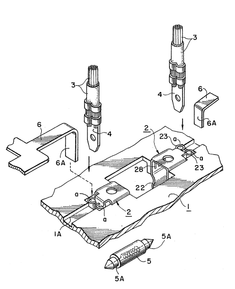
As shown more specifically in FIG. 1, connection device
according to the present invention includes connectors 2
mounted on an insulation substrate 1. The insulation
substrate ~ has a connector mounting portion 12 formed
thereon which includes confronting lugs 13, I3. Each of the
connectors 2 is integrally provided with a pair of clamping
pieces 22, 22 composed of resilient conductive plates as
shown in FIGS. 1 and 4 and a plug-in connection piece ~3.
The above connectors 2 are mounted on the socket
" " ~"~ . ";, : ; ~
2~0617~
mounting portion 12 by means of lugs 14 engaging a respective
one of the mounting holes 27 defined on the base of the
clamping pieces 22.
The insulation substrate 1 is made, for example, by
plastics molding techniques, and as shown in FIG. 1, has
mounting portions 12 for receiving a pair of connectors 2
defined on the upper surface thereof at prescribed intervals.
The mounting portion 12 each project outwardly with
respect to the upper surface of the substrate 1 and is opened
at the lower surface thPreof. A pair of lugs 13 to be
engageably locked with a respective connector 2 defined on
the confronting inner walls of the mounting portion 12 is
also provided.
The connector 2 is formed as shown in FIGS. 1 and 4 in
such a manner that a conductive plate 21 (preferably formed
of a conductive spring plate of phosphor bronze, nickel
silver, beryllium copper or the like) is punched
substantially into the shape as shown in FIG. 3--that is,
substantially bent to a U-shape to form a bottom at a
separating portion. Thus, ~ pair of the clamping pieces 22
serving as a holding socket are provided. The plug-in
connection piece 23 extending from a side of the above bottom
is substantially formed to the shape shown in FIG. 4 at the
same level with the bottom and is bent in parallel wi-th the
pair of the clamping pieces 220
The pair o~ clamping pieces 22 define the mounting holes
through which the lugs 13 in the socket mounting portion 12
are locked. The clamping pieces 22 also define a pair of
raised ribs for reinforcing the clamping pieces 22 and ~or
.
2~617~
establishing a space between the inner wall of the socket
mounting portion 12 and the connector 2 so as to provide a
vent (chimney) to allow for heat dissipation.
As shown in FIG. 2, each of the connectors 2 is mounted
in such a manner that the mounting holes 27 defined on each
base of the pair of the clamping pieces 22 are inserted into
the lugs 13 confrontingly disposed on the confronting wall
surfaces of the connector mounting portion 12 of the above
insulating substrate 1.
After the connectors 2 have been mounted, known tab
terminals to which lead wires 3 are press-fitted tightly into
a respsctive one of the connecting portions a of the plug-in
connection pieces 23. The conductive members 5A, 5A of a
straight tube-type lamp 5 are then mounted between the pair
of the clamping pieces 22.
Members shown by reference numeral 6 in FIG. 2 are band-
shaped narrow conductive plates known as "bus bars" and can
be used with the upright portions 6A, 6A thereof tightly
inserted into the connecting portions a of the plug-in
connection pieces 23 of the above-described connector 2. In
this case, however, grooves lA are preferably defined on the
surface of the insulating substrate 1 to accommodate the
band-shaped narrow conductive plates 6.
The plug-in connection plate 23 of connector 2 in the
present in~ention can be ~ormed in many different
orientations as shown in FIGS. 5 to 10.
A connector shown in FIG. 10 can be mounted as shown in
FIG. 12 through a state shown in FIG. 11. In this case,
1 .~, ., "' ,,~ ;., . ", ,,,,,;,, " ",, " ~ ,,,,,",," "," " : '" 'Il'''' ~'";' 1;'' '"'I ''' '': ' ' I '; ' ''` .:,
2~0~70
however, it is preferable either that (i) a pair of ribs lB,
lB project from the insulating substrate 1 to regulate the
position of the plug in connection piece in the horizontal
direction (as shown in the above respective FIGS.) or (ii)
that grooves lA are defined on the surface of the insulating
substrate 1 to regulate the position of tab terminals 4 and
lead wires 3 as shown in FIG. 13.
It should be noted here that like reference numerals in
FIGS. 1-2 and 11-13 refer to like structural elements.
The clamp type connection device according to the
present invention can include a conductive plate 2lA having a
shape shown in FIG~ 14 by folding it to shapes shown in FIGS.
15 and 16. The embodiments shown in FIGS. 15 and 16 are
essentially the same as the previous embodiments, exc~-pt that
the plug-in connection piece is asymmetricalO Thus, a tab
terminal 4 and a partially cutout cylindrical connection plug
4A can be inserted into a single plug-in portion a for use.
As shown in FIGS. 17 to 20, the clamp type connection
devices according to the present invention can comprise an
insulating ~ubstrate 1 having a connector mounting portion 12
provided with confronting lugs 13 formed thereto as shown in
FIG. 17. Connectors 2 each integrally provided with a pair
of clamping pieces 22 and made of a resilient conductive
plate formed to a shape shown in FIG. 19 and also provided.
In addition, these embodiments have dual plug-in contact
pieces 23 as shown in FIGS. 17 and 20. The connectors 2 are
mounted on the connector mounting portion 13 by means of the
lugs 13 extending into the mounting holes 27 ~ormed at each
base of the clamping pieces as shown in FIGS. 18 and 29.
,. .
2~6~L7~
In the above embodiments, the plug-in connection piece
23, can be formed in different orientations as shown in FIGS.
21 to 26.
Furthermore, a conductive plate having a shape shown in
FIG. 27 may be formed into a shape as shown in FIG. 28 such a
dual side face contact asymmetrical plug-in connection piece
23 having a conductiv~ piece 23A may be integrally formed
with a connector 2.
Note that each of FIGS. 29 to 33 is a cross-sectional
view of a main part of an embodiment of a connector 2 mounted
on an insulating substrate 1, wherein the same reference
numerals as used in the above embodiments are used to
designate the same structural components.
Since the above embodiments shown in FIGS. 17 to 33
1 15 include the dual side face contact type plug-in connection
I piece 23, the tab terminal 4 and the narrow conductive plate1 6 (bus bar) are in tight pre6s-fitted contact so that
electrical resistance is minimized and thus less heat is
produced therefrom.
I 20 The clamp type connection device according to the
¦ present invention can also be provided as shown in ~IGS. 34
~ to 51.
I
I More specifically, as shown in FIGS. 34 to 37, a
clamping type connection device comprises an insulating
substrate 1 having a connector mounting portion 12 provided
with confronting lugs 13. Connectors 2 each provided with a
pair of alamping pieces 22 are made from a resilient
conductive plate formed into a shape shown in FIG. 36.
'
,,'~ :,
2~170
Mounting holes 27 are defined on each base of the clamping
pieces 22. A confronting conductive piece 25 is formed by
folding a conductive piece 23A which projects from the base
2A of each of the connectors 2 into a U-shape as shown in
FIGS. 34 and 37. The above-described connectors 2 are
mounted on the connector mounting portion 12 by engaging the
lug 13 within mounting holes 27 of the substrate 1 as shown
in FIGS. 35, 47 and 50.
When the outer surface of the confronting conductive
piece 25 is pressed by support pieces 24A ~formed by folding
a conductive plate shown in FIG. 45 into a U-shape at the
sides 23B of a conductive piece 23A) as shown in FIG. 46, the
strength by which the tab terminal 4 is inserted into the
plug-in piece 23 is increased.
Note that, as shown in FIGS. 36 and 45, when a slit S is
defined at substantially the center of the confronting
conductive piece 5, the single confronting conductive piece
is divided into two portions and tab terminals 4 having a
different thickness can be especially tightly inserted to the
opposite sides thereof using the slit S as a border-line.
In another embodiment, the plug-in connection piece 23
composed of dual side face type contact elastic pieces
integrally formed with the connector 2 can also provide in
different orientations as shown in FIGS. 38 to 44.
Note that each of FIGS. 47 to FIG. 51 is a cross
sectional view of a main part of an embodiment of a connector
2 mounted to an insulating substrate 1, wherein the same
xeference numerals as used in the above embodiments are used
to designate the same structural members.
:,, . ~ .
.,,: ,, .
23~617~
The lamp type connection device according to the present
invention can also be achieved as shown in FIGS. 52 to 71.
More specifically, as shown in FIGS. 52 to 55, a
clamping type connection device comprises an insulating
substrate l having a connector mounting portion 12 provided
with confronting lugs 13 shown in FIG. 52. Connectors 2 are
each provided with a pair of clamping pieces 22 made of a
conductive plate having elasticity as shown in FIG. 54.
Mounting holes 27 are defined in each base of the clamping
pieces 22. A confronting conductive piece 25 is folded into
a U-shaped portion 24 from the side 23B of a conductive piece
23A which project from the base 2A of each of the connectors
2 as shown in FIG. 55. The connectors 2 are thus mounted on
the connector mounting portion 12 by engaging the lugs 13
with the mounting holes 27 as shown in FIG. 53 and 66.
Note that, as shown in FIG. 54 and 64, when a slit S is
defined at substantially the center of the confronting
conductive piece 25, the single confronting conductive piece
is divided into two portions and tab terminals 4 having a
different thickness can be especially tightly inserted into
the opposite sides thereof using the slit S as a border-line.
In this embodiment, the plug-in connection piece 23 can
be also formed in different orientations as shown in FIGS. 56
to 63. Alternatively, two confronting conductive pieces 25,
25 can be formed as a pair.
Mo.re specifically, the pair of conductive pieces may be
formed in such a manner that a conductivs plate having a flat
shape as shown in FIG. 64 may be formed into the shape shown
.
~' " ,' ' ;.' '" " ', ''~ "' ' " '; ' '' ' ' " i'' '~' ' 'i'` ' ' " ''' ' ' ' " " ' ' . '
2~6~70
in FIG. 65 so that the confronting conductive pieces 25 of
dual side face contact type symmetrical plug-in piece 23 are
integrally formed with the connector 2.
Each of FIGS. 66 to 71 is a cross sectional view of a
main part of an embodiment of a connector mounted to an
insulating substrate 1, wherein the same numerals as used in
the above-described embodiments are used to designate the
same structural members.
Since a pair of clamping pieces 22 and the plug-in
connection piece 23 having the plug-in connection portion a
are integrally formed with a single connector 2, the devices
of the present invention can be realized using less resources
at lower costs. Furthermore, a straight tube lamp, glass
tube fuse or the like can be held tightly by the pair of
clamping pieces 22 in use. The tab terminal 4, narrow
conductive plate 6 (bus bar), the partially cutout
cylindrical connection plug 4A or the like can also be
directly and tightly inserted into the plug-in connection
piece 23. As a result, contact resistance can be minimized
and thus less heat is produced. Finally, soldering irons,
caulking tools and the like required by conventional
connector devices are not needed according to the present
invention. Thus, the present invention has many beneficial
effects. For example, the task of connecting wires and the
2~ like can now be easily carried out in a narrow and/or dark
location (such as the engine compartment of an automobile).
Since the mounting holes 27, 27 are defined on each base
of a pair of the clamping pieces 22 and the raised ribs 28
are defined at the outside surface thereof, resistance heat
produced by electrical current during operation can be
11 .
20~6~ 7~
effectively dissipated by the chimney effect provided by the
space defined between the connector 2 and the mounting
portion 12. Thus, the insulating substrate, as well as the
lead wire insulation, are not adversely affected by such
heat. In addition, the flexural rigidity of the bases of the
clamping pieces is maintained.
since the outer surface of the confronting conductive
piece 25 can be pressed by the support piece 24, an external
conductive piece such as a tab terminal 4 can be more tightly
inserted into the plug-in connection piece 23. Thus,
electrical contact can be maintained for prolonged time
periods and thus contact resistance can be maintained at
reduced levels in use.
12