Language selection

Search

Patent 2006480 Summary

Third-party information liability

Some of the information on this Web page has been provided by external sources. The Government of Canada is not responsible for the accuracy, reliability or currency of the information supplied by external sources. Users wishing to rely upon this information should consult directly with the source of the information. Content provided by external sources is not subject to official languages, privacy and accessibility requirements.

Claims and Abstract availability

Any discrepancies in the text and image of the Claims and Abstract are due to differing posting times. Text of the Claims and Abstract are posted:

  • At the time the application is open to public inspection;
  • At the time of issue of the patent (grant).
(12) Patent: (11) CA 2006480
(54) English Title: CAPACITIVE LIQUID LEVEL SENSOR
(54) French Title: SONDE CAPACITIVE DE NIVEAU DE LIQUIDE
Status: Deemed expired
Bibliographic Data
(52) Canadian Patent Classification (CPC):
  • 73/69
(51) International Patent Classification (IPC):
  • G01F 23/26 (2006.01)
(72) Inventors :
  • GOEKLER, LEWIS E. (United States of America)
(73) Owners :
  • STANDEX INTERNATIONAL CORPORATION (United States of America)
(71) Applicants :
(74) Agent: MALCOLM JOHNSTON & ASSOCIATES
(74) Associate agent:
(45) Issued: 1994-06-21
(22) Filed Date: 1989-12-21
(41) Open to Public Inspection: 1990-07-06
Examination requested: 1990-06-29
Availability of licence: N/A
(25) Language of filing: English

Patent Cooperation Treaty (PCT): No

(30) Application Priority Data:
Application No. Country/Territory Date
07/294,200 United States of America 1989-01-06

Abstracts

English Abstract


ABSTRACT

A non-intrusive fluid level detector including a single
point capacitive sensor mounted on the outside surface of a
receptacle such that capacitive principles can be utilized to
sense the level of a liquid contained within the receptacle.
The sensor assembly is disposed in a substantially fixed
position on the exterior wall of the receptacle wherein the
dielectric effect of the liquid changes the effective
capacitance of the sensing capacitor as the liquid rises and
falls within the receptacle. This change in effective
capacitance is detected by electronic circuitry included in the
detector device. In one embodiment, the fluid level detector
is directly mounted to a completely non-conductive receptacle.
In another embodiment, the fluid level detector is mounted to a
non-conductive window which is an integral part of a receptacle
fabricated out of a conductive material.


Claims

Note: Claims are shown in the official language in which they were submitted.


THE EMBODIMENTS OF THE INVENTION IN WHICH AN EXCLUSIVE
PROPERTY OR PRIVILEGE IS CLAIMED ARE DEFINED AS FOLLOWS:
1. A non-intrusive fluid level detector for detecting a
predetermined level of a liquid contained within an electri-
cally conductive receptacle, comprising:
a single capacitance plate mounted on said recep-
tacle and electrically insulated from said receptacle, said
capacitance plate being cooperative with said receptacle and
the liquid in the receptacle to produce a sensor capacitor
having a capacitance which varies in magnitude in accordance
with the level of liquid contained within the receptacle;
detection circuitry coupled to said capacitance
plate and responsive to a difference between a voltage decay
signal derived from said sensor capacitor and a reference
voltage decay signal derived from a reference capacitor to
provide an output signal when a predetermined voltage differ-
ence is detected therebetween; and
indicating means coupled to said detection circuitry
and responsive to said predetermined voltage difference as
detected by said detection circuitry to provide an indication
of predetermined level of liquid contained within the recep-
tacle.
2. The fluid level detector of claim 1, wherein said
detection circuitry and said capacitance plate are separate,
physically independent units which are coupled electronical-
ly.
3. The fluid level detector of claim 1 wherein said
capacitance plate is made of a copper plate.

11

4. The fluid level detector of claim 1 wherein said
capacitance plate includes mounting means for mounting said
plate to an exterior wall of the receptacle.
5. The fluid level detector of claim 1 wherein the de-
tection circuitry and capacitance plate are mounted on a cir-
cuit board, the circuit board including mounting means for
mounting said circuit board on a wall of the receptacle.
6. The fluid level detector of claim 5 including a
housing means comprising a unitary structure, wherein said
detection circuitry and said capacitance plate are embodied
within said housing means.
7. The fluid level detector of claim 6, wherein the
housing means includes mounting means for securing the hous-
ing means to an exterior wall of the receptacle.
8. The fluid level detector of claim 1, wherein said
predetermined voltage difference corresponds to the absence
of liquid in said receptacle.
9. The fluid level detector of claim 1, wherein said
indicating means includes an alarm lamp which is energized
when said predetermined voltage difference is detected.
10. A non-intrusive fluid level detector for detecting a
predetermined level of liquid in a container, comprising:
container means for containing the liquid, said con-
tainer means fabricated from an electrically insulating mat-
erial;
at least two conductive plates situated in the same
plane and mounted to said container means, said at least two
conductive plates being cooperative with liquid in the con-
tainer means to produce a sensor capacitor having a capacit-
ance which varies in magnitude in accordance with the

12

level of liquid contained within the container means;
detection circuitry coupled to said sensor capacitor
and responsive to a difference between a voltage decay signal
derived from said sensor capacitor and a reference voltage
decay signal derived from a reference capacitor to provide an
output signal when a predetermined voltage difference is
detected therebetween; and
indicating means coupled to said detection circuitry
and responsive to said output signal to provide an indication
of predetermined level of liquid contained within the con-
tainer means.
11. A non-intrusive fluid level detector for detecting a
predetermined level of liquid in a container comprising:
container means for containing the liquid, said con-
tainer means fabricated from a metallic, electrically con-
ductive material, said container means including a window of
non-conductive material as an integral portion of a wall of
said container means;
a single capacitance plate for mounting to said win-
dow of non-conductive material, said capacitance plate being
cooperative with said electrically conductive receptacle and
the liquid in the container means to produce a sensor capaci-
tor having a capacitance which varies in magnitude in accord-
ance with the level of liquid contained within the container
means;
detection circuitry coupled to said sensor capacitor
and responsive to a difference between a voltage signal

13

derived from said sensor capacitor and a reference voltage to
provide an output signal when a predetermined voltage differ-
ence is detected; and
indicating means coupled to said detection circuitry
wherein said indicating means is responsive to said output
signal to provide an indication of a predetermined level of
liquid contained within the container means.
12. A non-intrusive liquid level sensor for detecting a
predetermined level of liquid contained within a receptacle,
comprising:
a single capacitance plate mounted to said recep-
tacle, said capacitance plate being cooperative with the
liquid in the receptacle and the residual ground of the
receptacle to produce a sensor capacitor having a capacitance
which varies in magnitude in accordance with the level of
liquid contained within the receptacle;
detection circuitry coupled to said capacitance
plate and responsive to a difference between a voltage signal
derived from said sensor capacitor and a reference voltage
signal to provide an output signal when a predetermined
voltage difference is detected; and
indicating means coupled to said detection circuitry
and responsive to said predetermined voltage difference as
detected by said detection circuitry to provide an indication
of a predetermined level of liquid contained within the
receptacle.
13. The fluid level detector of claim 1 wherein said

14


detection circuitry includes:
first circuit means for receiving an oscillating
voltage signal and providing a voltage decay signal, decaying
over time in response to a negative transition in the
oscillating voltage signal;
second circuit means for providing the reference
voltage signal; and
third circuit means for comparing the voltage decay
signal and the reference voltage and providing said output
signal when a predetermined voltage difference is detected.
14. The fluid level detector of claim 1, wherein said
detection circuitry includes:
a voltage regulator circuit for providing direct
current source and reference voltage signals;
said square wave oscillator circuit for providing a
square wave oscillating signal to a reference capacitor and
to said sensor capacitor from the direct current source
voltage signal;
a reference capacitance circuit for providing a
first voltage decay signal, decaying over time in response
to a negative transition in the square wave oscillating
signal, as derived from the reference capacitor;
a first voltage comparator circuit for comparing the
output signal of the reference capacitance circuit to the
direct current reference voltage signal and providing a first
voltage comparator output signal;
a sensor capacitance circuit for providing a second


voltage decay signal, decaying over time in response to a
negative transition in said square wave oscillating signal,
as derived from said second capacitor;
a second voltage comparator circuit for comparing
the output of the sensor capacitance circuit to the output of
the first voltage comparator circuit and providing a second
voltage comparator output signal; and
a third voltage comparator circuit for comparing
the output of the second voltage comparator circuit to the
direct current reference voltage signal and providing a third
voltage comparator output signal to an indicator circuit for
providing and indication of when a predetermined voltage
difference is detected.
15. A non-intrusive capacitive liquid level sensor for
detecting a predetermined level of liquid in a container,
comprising:
non-conductive container means for storing liquid;
at least two conductive plates situated in the same
plane wherein said at least two conductive plates are co-
operative with the liquid in the container means to provide a
sensor capacitor having a capacitance which varies in magni-
tude with respect to the amount of liquid present between
said at least two conductive plates;
detection circuit means coupled to said sensor cap-
acitor, said detection circuit means including:
an oscillator circuit coupled to said sensor cap-
acitor for providing an oscillating voltage signal to said

16

sensor capacitor, said sensor capacitor providing a sensor
voltage decay signal as the voltage across said sensor
capacitor decays over time in response to a negative
transition in the oscillating voltage signal;
a reference capacitor circuit coupled to said
oscillator circuit for receiving said oscillating voltage
signal and providing a reference voltage decay signal, as the
voltage across said reference capacitor decays over time in
response to a negative transition in the oscillating voltage
signal;
a voltage comparator circuit coupled to said sensor
capacitor and to said reference capacitor circuit for
receiving and comparing said reference voltage decay signal
and said sensor voltage decay signal and providing an output
signal when a predetermined voltage difference is detected
therebetween; and
indicating means coupled to said detection circuit
means, responsive to said output signal to provide an
indication of the presence or absence of a predetermined
level of liquid in the container means.
16. A non-intrusive capacitive liquid level sensor for
detecting a predetermined level of liquid in a container,
comprising:
electrically conductive container means for storing
liquid, said container means including, as an integral
portion of a wall of said container means, a window of non-
conductive material;

17

a single capacitance plate for mounting to said
window of non-conductive material, wherein said single cap-
acitance plate is cooperative with said electrically conduc-
tive container means and the liquid therein to provide a
sensor capacitor having a capacitance which varies in magni-
tude with respect to the amount of liquid present in said
container means;
detection circuit means coupled to said sensor
capacitor, said detection circuit means including:
an oscillator circuit coupled to said sensor
capacitor for providing an oscillating voltage signal to said
sensor capacitor, said sensor capacitor providing a sensor
voltage decay signal as the voltage across said sensor
capacitor decays over time in response to a negative transi-
tion in the oscillating voltage signal;
a reference capacitor circuit coupled to said
oscillator circuit for receiving said oscillating voltage
signal and providing a reference voltage decay signal, as the
voltage across said reference capacitor decays over time in
response to a negative transition in the oscillating voltage
signal;
a voltage comparator circuit coupled to said sensor
capacitor and to said reference capacitor circuit for receiv-
ing and comparing said reference voltage decay signal and
said sensor voltage decay signal and providing an output
signal when a predetermined voltage difference is detected
therebetween; and

18


indicating means coupled to said detection circuit
means and responsive to said output signal to provide an
indication of the presence or absence of a predetermined
level of liquid in the container means.

19

Description

Note: Descriptions are shown in the official language in which they were submitted.


o


FIELD OF THE' INVENTIO~


The present invention relatles to fluid level detectors and
more particularly, to a non-intrusive fluid lavel detection
system for detecting the level of a liquid contained within a
receptacle.


BACKGRQyND OF THE INVENTION


Fluid level detectors which sense the level of a liquid
contained within a rece~tacle are well known for use in
conjunction with automotive engines. Historically, such
detectors have been made in the form of float operated switches
involving movin~ parts which are subject to friction and wear.
Other devices utilize an electrical probe to detect fluid
levels by measuring the conductivity of the coolant. However,
these devices rlequire complicated current amplifying systems
because there is often an insufficient amount of current
passing through the electrodes to power an indicator lamp. In
either of these systems, the measuring sensor is lo ated in the
fluid where contaminànts are likely to collect on the sensor
and disturb the fluid le~el measurement. Furthermore, the

devices in the prior art, as described, are categorized as
"intrusive" in that they require an opening into the receptacle
containing the fluid. This creates an additional potential for


- 2 -


: . . , ` ,.: .-: : ~ , : :`, :,: :.. `. , .: . . - , ` ~ ~ .

3~


fluid leaks as well as potential deterioration of the sensing
Zevices.
Due to the problems discussed above, it has become
desirable to employ non-intrusive means to sense fluid levels
contained in receptacles. These non-intrusive systems
typically involve wave propagation techniques which are
implemented throu~h a transmitter~receiver system. Typically,
these systems involve the transmission of an ultrasonic signal
from a transmitting transducer through a fluid to a receiving
transducer. Such ultrasonic transmission systems require a
liquid transmission medium in order to carry the ultrasonic
sign~l from the transmitting transducer to the receiving
transducer. Lack of signal at the receiving transducer relates
to a laclc of liquid transmission medium, activating a no fluid
present indication. ~owever, a failure in the transducer pair
or in their respective electronic connections results in a lac~
of signal from the receiving transducer which, in turn,
activates the normal ~ailure mode thereby falsely indicating a
dry or no fluid present state.
The lncreasing importance of monitoring fluid levels in
automotive and other applications is creating a need for more
reliable non-intrusive fluid level sensors. It is, therefore,
important that a fluid level detection system be developed
which can provide reliable data and which does not require
contact with the fluid being measured.


'~0i')69~


SUMMARY OF THE INVENTIQN


In accordance with the present invention a non-intrusive
fluid level detector is provided or mounting on the e~terior
wall of a receptacle. The present invention provides single
point sensing of predetermined low levels of fluids, as in an
automobile cooling system or a windshield washer solvent
reservoir, without contact with the liquid being sensed. The
invention also provides an electrical signal which can energize
an alarm light or other indicator. The fluid level detector of
the present invention incorporates capacitive sensor means
established relative to a fluid receptacle in a substantially
fixed relation on the outside wall of the receptacle. The
capacitive sen~or can be made to be an integral part of a
printed circuit containing electronic detection circuitry,
thereby making the device self-contained. This sensor assembly
is mounted on the exterior wall of the fluid receptacLe at a
position to sense the lower limit of acceptable fluid level~
The present invention utilizes capacitive principles to
sense the level of a liquid contained within a non-metallic

i
receptacle. As a liquid rises and falls in the container, the
die:Lectric affect of the liquid changes the effective
capacitance of the sensing capacitor which is detected by
electronic circuitry coupled to the sensor. The device remains ;~


- 4 -

64~0


activated whenever power is applied and provides an indication
to the user only when the low liquid level is detected.
The present invention is a passive device in that the
device monitors the level of the liquid within the receptacle
at all times and requires no interaction or other monitoring by
the user.
DESCRIPTION OF THE DRAwINGs


The invention will be more fully understood from the
following detailed description taken in conjunction with the
accompanying drawings, in which:
Fig. lA is a schematic of the circuitry of the present
invention;
Fiq.lB is a schematic of an alternative capacitive sensing
circuit;
Figs. 2A-2E are signal diagrams o signals at certain test
points in the schematic diagram of Fig. l;
Figs. 3A and 3B are e~ploded perspective views of a
preferred embodiment of the liquid level sensor of the present
invention; and

, . . , . :
Figs. 4A and 4B are two-dimensional views of alternative - ;

mo`unting configurations of the present invention.

:~:


DETAILED DESCRTPTION OF THE INVENTI~
. ~, ~'.'
Fig. lA illustrates the circuit diagram of one embodiment
of the fluid level detector of the present invention. The


- 5 ~

2'~


supply voltage for this circuit is typically provided by
a 12-volt automobile battery which is reduced to a 5-volt DC
source voltage by means of a voltage regulator comprising the
combination of resistor Rl and zener diode Zl. Capacitor Cl
serves as a filter for this voltage supply regulator.
The detector of Fig. lA incorporates an amplifier Al in
conjunction with a resistor/capacitor network R4 and C2 and
resistors R5 and R6 to form a square wave oscillator. A
reference voltage is supplied from the voltage regulator where
the reference voltage value is determined by the voltage
divider circuit R2/R3. This voltage serves as a reference
voltage for the square wave oscillator and voltage comparators
A2, A4 located in the circuit, as will be described.
The output of the square-wave oscillator described above,
is shown as the s~uare wave of Fig. 2A. The oscillator
produces an alternating electrical output which causes
capacitors C3 and C4 to charge through diodes Dl and D2,
respectively, where capacitor C4 is a sensor capacitor and
capacitor C3 is a reference capacitor. As stated, capacitor C4
is the sensor capacitor wherein the two conductive surfaces of
the capacitor are plate Pl and the residual ground of the
receptacle 10 through its mounting arrangement. The dielectric
of the capacitor is the fluid in the receptacle 10 such that
the capacitance value of C4 varies relative to the fluid level


-- 6 --


,

2~ 6~


in the receptacle. The capacitance value of capacitor C3 is
adj~stable to match the value o capacitor C4 when a
predetermined liquid level is sensed, i.e., at the critical
level.
Fig. lB shows an alternative embodiment of the present
invention wherein plates ~2 and P3 are added to the
configuration of sensing capacitor C4. The plates P2 and P3
are connected to circuit ground. A lower level capacitance is
provided by plates Pl and P2, and an upper level capacitance is
provided by plates Pl and P3.
When the voltage from the oscillator circuit at test
point 1 ~TPl) makes a transition from positive to negative,
capacitors C3 and~C4 begin to discharge through resistors R9
and R10, respectively. It is the difference in voltage decay
across resistors R9 and R10 due to the capacitance values of
capacitors C3 and C4 which enables ~he circuit to determine if
there is sufficient fluid in the receptacle 10.
Referring again to Fig. lA, voltage comparator A2 compares
the voltage at test point 2 (TP2) with the reference voltage
set by resistors R2 and R3. Figs. 2B and 2C illustrate that
when the voltage at TP2 decreases below the ire erence
. ':
voltage Vl, due to the discharge of capacitor C3, the output of
the comparator ~2 reference voltage at TP3 drops to zero. The ~,
time between the point where capacitor C3 begins to discharge


-- 7 --

z~


and the output of the comparator A2 drops to zero is used as a
reference time Tl. Similarly, the comparator A3 compares the
square wave output of the comparator A2 with the voltage decay
signal across resistor RlO due t:o sensor capacitor C4 at test
point TP4.
As shown in Figs. 2C-2E, if the discharge time T3 of
capacitor C4 is longer than the reference time Tl established
by the comparator A2, the output of the comparator A3 remains
high. Conversely, if discharge time T3 is shorter than
reference time Tl, due to a faster discharge rate in C4, the
output of the comparator A3 pulses low for a period of time in
which the discharge voltage at TP4 is less than the output
voltage of the comparator A2 (TP3). In application, this pulse
is actually a current pulse rather than a voltage pulse.
The output of the comparator A3 is an open collector type
output which allows capacitor C5 to charge through resistor
R14. If the output of A3 pulses low, capacitor C5 discharges
to ground and the voltage at test point 5 ~TP5) goes to zero.
Finally, the reference voltage set by resistors R2 and R3
is compared to the voltage at TP5 through the comparator A4.
If the voltage at TP5 is high, representing capacitance C4 to
be of a relatively large value and corresponding to a
sufficient fluicl in the reservoir, the output of A4 will pull
to ground and transistor TRl will not conduct. However, if the


~o~


voltage at TP5 is low, which means that capacitance C4 is not
of a sufficient value, the output of A4 will bias transistor
TRl such that current will flow through the collector and
energize lamp Ll.
In operation, when the fluid level in the receptacle is
full, capacitor C4 takes a certain length of time to discharge;
when the fluid is at a lower level, capacitor C4 takes a
shorter period to discharge. Thus, as the fluid level in the
receptacle decreases, the capacitance of capacitor C4 also
decreases, which, in turn, decreases the discharge time of
capacitor C4. This causes a current pulse to be output by
comparator A3 during the period in which the discharge voltage
from capacitor C4 is less than the voltage output from
comparator A2. The current pulse causes capacitor C5 to
discharge, thereby allowing the output of comparator A4 to rise
and allowing current to flow through transistor TR1 to lamp
Ll. When current flows through lamp Ll, the indicator lamp is
lit. `
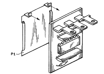
An exploded perspective view of the present invention is -
shown in Figs. 3A and 3B where sensor plate Pl is shown as an
integral part of the assembled unit. In an alternative
embodiment, capacitor plate Pl can be physically separated from
the electronic circuitry of the invention such that the sensor
plate Pl iS attached to the fluid receptacle and is

Z~ )6~0


electronically coupled to the corresponding electronic
circuitry located at a position which is isolated from the
receptacle.
In accordance with the pr~3sent invention, as shown in
Figs. 4A and 4B, the sensing capacitor can be mounted to the
receptacle 10 in various ways depending on whether the
receptacle 10 is made of a conductiYe or a non-conductive
material. In one embodiment of the invention, shown in --
Fig. 4A, the fluid receptacle 10 is completely made of a
non-conductive material and the sensing capacitor plate Pl is
mounted directly to the surface of the receptacle 10. In
another embodiment of the invention, shown in Fig. 4B, the
receptacle 10 is made of a conductive material escept for a
relatively small window 12 of non-conductive material making up
a portion of a wall of the receptacle 10 upon which the
capacitive plate Pl is mounted.
The fluid level detector of the present invention permits
the monitoring of a level of a fluid contained in a receptacle
wherein there is n~ engagement between the sensing device and
the liquid. The disclosed invention is not to be limited by
what has been particuiarly shown and described e~cept as
indicated by the present claims.
.. ,~
: :`
':."
- 10 ~

, ~

Representative Drawing
A single figure which represents the drawing illustrating the invention.
Administrative Status

For a clearer understanding of the status of the application/patent presented on this page, the site Disclaimer , as well as the definitions for Patent , Administrative Status , Maintenance Fee  and Payment History  should be consulted.

Administrative Status

Title Date
Forecasted Issue Date 1994-06-21
(22) Filed 1989-12-21
Examination Requested 1990-06-29
(41) Open to Public Inspection 1990-07-06
(45) Issued 1994-06-21
Deemed Expired 1997-12-22

Abandonment History

There is no abandonment history.

Payment History

Fee Type Anniversary Year Due Date Amount Paid Paid Date
Application Fee $0.00 1989-12-21
Registration of a document - section 124 $0.00 1990-07-20
Maintenance Fee - Application - New Act 2 1991-12-23 $100.00 1991-11-27
Maintenance Fee - Application - New Act 3 1992-12-21 $100.00 1992-12-16
Maintenance Fee - Application - New Act 4 1993-12-21 $100.00 1993-12-02
Maintenance Fee - Patent - New Act 5 1994-12-21 $150.00 1994-12-01
Maintenance Fee - Patent - New Act 6 1995-12-21 $150.00 1995-12-01
Owners on Record

Note: Records showing the ownership history in alphabetical order.

Current Owners on Record
STANDEX INTERNATIONAL CORPORATION
Past Owners on Record
GOEKLER, LEWIS E.
Past Owners that do not appear in the "Owners on Record" listing will appear in other documentation within the application.
Documents

To view selected files, please enter reCAPTCHA code :


To view images, click a link in the Document Description column. To download the documents, select one or more checkboxes in the first column and then click the "Download Selected in PDF format (Zip Archive)" or the "Download Selected as Single PDF" button.

List of published and non-published patent-specific documents on the CPD .

If you have any difficulty accessing content, you can call the Client Service Centre at 1-866-997-1936 or send them an e-mail at CIPO Client Service Centre.


Document
Description 
Date
(yyyy-mm-dd) 
Number of pages   Size of Image (KB) 
Representative Drawing 1999-07-26 1 13
Cover Page 1997-09-23 1 62
Abstract 1997-09-23 1 34
Claims 1997-09-23 9 465
Drawings 1997-09-23 4 171
Description 1997-09-23 9 470
Prosecution Correspondence 1990-06-28 1 32
PCT Correspondence 1994-03-28 1 33
Prosecution Correspondence 1995-06-10 3 98
Office Letter 1990-06-20 1 17
Office Letter 1990-08-15 1 21
Examiner Requisition 1992-12-10 1 55
Fees 1995-12-01 1 35
Fees 1994-12-01 1 33
Fees 1993-12-02 1 29
Fees 1992-12-16 1 26
Fees 1991-11-27 1 25