Note: Descriptions are shown in the official language in which they were submitted.
Z0~6996
-
TITLE OF THE INVENTION
A CLAMPING BAND
FIELD OF THE INVENTION AND RELATED ART STATEMENT
The present invention relates to a clamping band to clamp
joint sections of hose such as gas hose, car boot, etc.
A metal clamping band, which clamps hose, car boot, etc.
in one action, has been known, e.g. Japanese Patent Publication
Gazette No. 50-14702. The conventional clamping band is shown
in Fig. 19. It comprises a band 4, which is formed like a ring
and whose both ends are connected to form an overlap section 3,
a lever 5 fixed to the overlap section 3, and a clasp 6 for
fixing the end section of the lever to the band 4 when the band
4 is shortened its diameter by the lever 5 with the action of
levers.
A clamped member such as hose has been inserted in the
band 2 and has been connected to a pipe, etc. beforehand. Then,
the band 2 is travelled to the joint section and the lever 5 is
rotated in the direction shown by the arrow. In this rotation,
the front end 5a of the lever 5 works as the power point;
another end 5b contacting the band 4 of the lever 5 as the
fulclum point, so that the overlap section 3 shortens the
diameter of the band 4 as the active point.
The front end of the lever 5 of the clamping band 4
shortened to clamp is fixed by the clasp 6 and kept the clamping
status.
The clamping band 2 can be used quickly and easily but it
is impossible to clamp a clamped member after the clamped member
is connected to a pipe, etc. Therefore, in case that the clamp-
2006996
71429-15
lng band should be exchanged because of repalrment, etc., the
clamped member must be detached.
The conventlonal clamping band is inconvenient for
repairment because of that reason. If the clamped member cannot
be detached, the clamping band cannot be exchanged.
A dividable clamping band shown in Fig. 20 is also
known. Both ends of a band 7 are overlapped and connected to form
like a ring. There is proiected an ear 8 formed like a gate from
the outer face 7a of the band. The clamping band is shortened its
diameter by crushlng the ear 8. It can be attached to round the
clamped member after the clamped member ls connected. However,
the clamping band is made of metal, so that crushed ear 8 springs
back in the end and lt ls lmposslble to clamp tlghtly.
OBJECT AND SUMMARY OF THE INVENTION
The ob~ect of the present lnventlon ls to provide a band
clamp or clamping band which can be easily attached and clamped
after the member to be clamped such as hose, etc. has been
connected, and which has hlgh clamping force.
The present invention provides a band clamp comprising
an elongated bendable band having first and second ends, and flrst
and second faces forming respectively a convex outer face and a
concave inner face when the band is bent around an obiect,
fulcrurn means formed on the first face of the band close to
the first end thereof;
a lever, having one end shaped to releasably engage the
fulcrum means, the second end of said band being attached to said
Z006996
interval. The engage hole can be formed by projecting a portion
of the band outward at the one end section thereof and by open-
ing the part of the portion projected. The one end section of
the band may be bent outward along the line crossing the engage
hole. There may be formed an extended section extending forward
from the line. A pressing piece may be provided in the vicinity
of the other end of the band fixed by the lever to fill up the
gap between the fulclum point of the lever and the other end
section of the band which is formed when the diameter of the
band is shortened by rotating the lever.
BRIEF DESCRIPTION OF THE DRAWINGS
The present invention will be apparent from the following
description, reference being had to accompanying drawings
wherein preferred embodiments of the present invention are
clearly shown.
In the drawings:
Fig. 1 shows a side view of the clamping band of the
present invention;
Fig. 2 shows a bottom view of the clamping band developed;
Fig. 3 shows a side view of the clamping band of Fig. 2;
Fig. 4 shows a partially sectional side view of the
clamping band bent along the line crossing the engage hole;
Fig. 5 shows a partial perspective view of the principal
part of the clmaping band;
Fig. 6 shows a side view of the clamping band of another
embodiment;
Fig. 7 shows a partially sectional view of the clamping
band developed of Fig. 6;
2006996
71429-15
In the drawlngs:
Flg. 1 shows a slde vlew of the clamplng band of the present
lnventlon;
Flg. 2 shows a bottom vlew of the clamplng band developed;
Flg. 3 shows a slde vlew of the clamplng band of Flg. 2;
Fig. 4 shows a partlally sectional side view of the clamping
band bent along the line crossing the engage hole;
Flg. 5 shows a partlal perspectlve vlew of the prlnclpal part
of the clamplng band;
Flg. 6 shows a slde vlew of the clamplng band of another
embodlment;
Flg. 7 shows a partlally sectlonal vlew of the clamping band
developed of Flg. 6;
Z006996
Fig. 8 shows a partial plan view of the clamping band
developed of Fig. 6;
Fig. 9 shows an explanation view of the clamping band of
Fig. 6 in clamping status;
Fig. 10 shows a side view of the clamping band of another
embodiment;
Fig. 11 shows a plan view of the clamping band developed
of Fig. 10;
Fig. 12 shows a side view of the clamping band developed
of Fig. 10;
Fig. 13 shows a partial perspective view of the principal
part of the clamping band of Fig. 10;
Fig. 14 shows a development view of a modified example of
the clamping band;
Figs. 15 and 16 show partial side views of other
embodiment;
Fig. 17 shows a side view of the clamping band which has a
pressing piece;
Fig. 18 shows explanation views of modified example of the
projected section of the lever; and
Figs. 19 and 20 show side views of conventional clamping
band.
DETAILED DESCRIPTION OF PREFERRED EMBODIMENTS
Preferred embodiments of the present invention will now be
described in detail with reference to accompanying drawings.
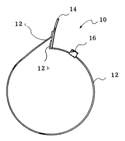
Fig. 1 shows a side view of the clamping band of the
present invention and Fig. 2 shows a bottom view of the band
developed.
ZQ06996
The clamping band 10 comprises a band 12 made of rectangle
metal plate, a lever 14 for shortening the diameter of the band
12, and a clasp 16 for fixing the lever 14.
There is bored an engage hole 12a at one end section of
the band 12. The other end of the band 12 is fixed at the mid
section by spot welding. There is formed a projected section,
which can fit in the engage hole 12a of the band 12 and which
can be the fulclum point when the lever 14 shortens the diameter
of the band 12, at one end of the lever 14. The length of the
projected section 14a is preferrably longer than the thickness
of the band 12.
In Fig. 2, one end section of the band 12 is bent along
the line 19 (shown by a solid line) crossing the engage hole 12a.
The end side of the line 19 is formed as a standing section 12b.
Note that, there is fixed a clasp 16, which is formed U shape
near the engage hole 12a of the one end section of the band 12,
bridging over the band 12 and its both side sections are opened
outwardly. Namely, standing pieces 16a and 16a are outwardly
standing and clipping the band 12.
Next, clamping process with above stated clamping band 10
will be described.
A clamped member such as hose, etc. is connected to a pipe,
etc. The clamping band 10 is wound on the outer face of the
joint section of the clamped member. The proiected section 14a
of the lever 14 of the clamping band 10 is fitted in the engage
hole 12a of the band 12. Note that, the standing section 12a is
bent along the line 19 crossing the engage hole 12a, it will be
easy to engage the projected section 14a of the lever 14 with
the engage hole 12a of the band 12, and the band 12 is held in
zoa6gg6
position if the lever 14 is contacted the standing piece 12b.
Successively, the lever 14 is rotated around the projected
section 14a, which is fitted in the engage hole 12, as the
fulclum point to shorten the diameter of the band 12. The lever
14 is rotated until it contacts the band 12. Rotating the lever
14, the welded section 12c of the band 12, which is welded to
the lever 14, pushes down the standing piece 12b, so that there
are no projecting parts on the outer face of the clamping band.
The front end of the lever 14 is locating between the standing
pieces 16a and 16a of the clasp 16. The standing pieces 16a and
16a are hit down inward by hammer, etc. to fix the lever 14.
Note that, as shown in Fig. 5, the one end section of the band
12 is bent along the line crossing the engage hole 12a, the
engage hole 12a is bored from the standing piece 12b to the
portion which contacts the clamped member. Therefore, the
projected section 14a of the lever 14 is fitted in the engage
hole 12a, even if the lever 14 is lying.
Fig. 6 shows a modified example of the clamping band 10.
This clamping band 20 has an engage proiection 22 instead of the
engage hole 12 of above stated clamping band 10. The engage
projection 22 is formed by punching the band 12 with a punch,
etc., and an opening 22a is bored in the clasp 16 side of the
projection 22. Fig. 7 shows the clamping band developed with
the engage projection 22 in section. And Fig. 8 shows a bottom
view of the clamping band. The lever 24 for shortening the
diameter of the band 12 is welded at the one end section of the
band 12 of the clamping band 20. There is formed a mountain-
like projection 24 at the front end of the lever 24 (see Fig. 8).
The projection 24a is diagonally inserted in the opening 22a of
200699S
the engage projection 22 when the band 12 is formed like a ring
(see Fig. 6).
Clamping action of the clamping band 20 will be described.
A clamped member 30 such as hose, etc. is connected to a
pipe 32, then the clamping band 20 is wound on the outer face of
the joint section of the clamped member 30. The projection 24a
of the lever 24 of the clamping band 20 is fitted to the engage
projection 22 of the band 12. And the lever 24 is rotated
around the projection 24a as the falclum point to shorten the
diameter of the ring-like band 12. Then the front end of the
lever 24 is fixed by the clasp 16 in the same manner as described
above ~see Fig. 9). Note that, the opening 22a of the engage
projection 22 is opened on the clasp 16 side only, the projection
24a engaging with the engage projection 22 of the lever 24 is
held in position. The portion from the engage projection 22 to
the front end of the band 12 contacts the clamped member, so
that a step formed by both end sections of the band 12 can be
smaller than the clamping bands shown in Figs. 1-5. The portion
from the engage proiection 22 to the front end is an extended
section.
Fig. 10 shows another embodiment and it is a side view
before clamping. Fig. 11 shows a plan view of the clamping band
developed. Fig. 12 shows a side view thereof.
The clamping band 110 comprises, as same as former
embodiments, a band 112, a lever 114 for shortening the diameter
of the band 112, and a clasp 116 for fixing the lever 114.
There is bored an engage hole 112a at one end section of the
band 112. A standing section 112b is formed by outwardly bending
along the line 119 crossing the engage hole 112a. While, the
Z006996
other end of the band 112 is bent to clip the upper end of the
lever 114 and is fixed to the lever 114 by spot welding . There
is formed a projection 114a, which can be fitted in the engage
hole 112a of the band 112 to be the fulclum point when the lever
114 shortens the diameter of the band 112, at the one end of the
lever 114. The status where the projection 114a of the lever
114 is fitted in the engage hole 112a of the band 112 is shown
in Fig. 13. The clasp 116 is fixed along the inner side of the
band 112. The clasp 116 has an extended section 116b, which
extends forward from the standing section 112b of the band 112.
There are provided standing pieces 116a and 116a at the rear end
of the clasp 116. The standing pieces 116a and 116a are located
the position corresponding to the front end of the lever 114
which is rotated on the projection 114a as an axis to lie. The
lever 114 lying is fixed by bending the standing pieces 116a and
116a inward with a hammer, etc.
The process of clamping hose with this clamping band 110
will be described.
A clamped member such as hose, etc. is connected to a
pipe, etc., and the clamping band 110 is wound on the outer face
of the clamped member. The projection 114a of the lever 114 of
the clamping band 110 is fitted in the engage hole 112a at the
one end of the band 112. Note that, the standing section 112b
is bent along the line 119 crossing the engage hole 112a, so
that it is easy to fit the projection 114a of the lever 114 in
the engage hole 112a, and the band 12 is held in position if the
lever 114 contacts the standing piece 112b of the band 112 (see
Fig. 13). Successively, fitting the projection 114a of the
lever 114 in the engage hole 112a, the lever 114 is rotated to
;~006996
shorten the diameter of the band 112 on the one end of the lever
114 as an axis for clamping. Then, the lever 114 is forced down
until it contacts the band 112, and the lever 114 is fixed by
bending the standing pieces 116a and 116a inward by a hammer,
etc. The extended section 116b of the clasp 116 is provided
along the joint section of both ends of the band 112 from inside,
so that the projection 114a of the lever 114, which is fitted in
the engage hole 112a at the one end section of the band 112,
does not damage the clamped member.
In the clamping band 10 shown in Figs. 1-5, the one end
section of the band is bent along the line crossing the engage
hole, but the projection of the lever can be fitted in the
engage hole of the band without bending, so that the fitting
section has the function of the fulclum point. In the clamping
band 10 without bending along the line 19 crossing the engage
hole 12a, a plurality of engage holes 12a... can be bored ~see
Fig. 14). With this structure, one clamping band can clamp
members having various size. Further, clamping force of the
clamping band 10 can be adjustable.
In the clamping band shown in Figs. 1-5, its clamping
status is shown in Fig. 15, the standing section 12b of the band
12 is folded back, so that a welded section 12c, which is near
the other end of the band 12 fixed to the lever 14, does not
contact the clamped member; the gap 40 is formed, so that uniform
clamping force can not work to the clamped member. To fill up
the gap 40, there may be provided a pressing piece 42 shown in
Fig. 16, whose inner face is formed an arc, on the inner face of
the band corresponding to the gap 40. The pressing piece 42 may
be an arc plate. Like the clamping band 110 shown in Fig. 10,
6996
the extended section 116b may be provided at the one end section
of the band ~see Fig. 17).
If the engage hole is a bottomed hole, which is formed by
drawing, etc., the strength of the engage hole and the standing
section will be raised.
If the projection of the lever is formed tapered-shape as
shown in Fig. 18(a) and ~b), it is easier to fit the projection
in the engage hole.
Preferred embodiments of the present invention have been
described in detail, the present invention is not limited to
above stated embodiments, for example, the shape of the
projection of the lever and the shape of the engage hole of the
band can be changed in user's option, many modifications can be
allowed without deviating the scope of the invention.
The clamping band of the present invention has following
advantages.
It can wind on the outer face of the joint section of the
clamped member after the clamped member such as hose, etc. is
connected to pipe, etc., and can easily clamp the clamped member
by the lever with the action of levers. The projection of the
lever is fitted in the engage hole, etc. of the band, and the
lever is rotated around the fitted section as the fulclum point
to shorten the diameter of the band, so the fulclum point is
held in position and it is easier to do clamping work. Further,
in case of bending the one end of the band outward, the lever is
held by the bent section, so it is easier to fit the projection
of the lever in the engage hole of the band.
1 0