Note: Descriptions are shown in the official language in which they were submitted.
2'40'043
AUTOMATIC SAFETY DEVICE FOR FIRE ARMS
SPEEIFICATIOI~
The present invention generally concerns those
fire arms which are operated starting from their
open-bolt position, and in particular an automatic
safety device for said fire arms and espeeialTy
designed for automatic guns.
Fire arms which are operated starting from
their open-bolt position have to be first manually
cocked by taking back the bolt till it is engaged by
the tripping mechanism of the arm. This operation
may however cause an accidental and therefore
dangerous shot. In fact, a faulty or incomplete
manual move of the bolt or its release during its
zoo~Q43
- 2 -
cocking or a .shock taking the ammunition into the
barrel causing an uncontrolled shot cannot be
excluded.
The purpose of the present invention is in-
stead to prevent such an eventuality and thus its
possible consequences.
Specifically, it is the purpose of the present
invention to make available an automatic safety de-
vice for the above mentioned type of fire arms which
is able to immediately stop the bolt in whichever
position in ease of a faulty or incomplete- operation
or in ease it moves back by accident, in order to
prevent said bolt from advancing before- it is safely
engaged in the tripping mechanism of the arm; thus
~~obliging" the operator, while he is cocking the
arm, to take the boltlock on the tripping mechanism.
Said purpose is fulfilled by a safety device
featuring the details specified in claim 1.
The device is therefore performinng the fol-
lowing functions owing to its special design.
- It goes into action only the moment the arm is
cocked: while the arm is operating either auto-
matically or with individual shots, the whole
safety device is cut off and thus inactive;
_ With the proposed solution the bolt of the arm
. ~40'~443
r
- 3 -
cannot be mc~nur~lly displaced without activating
the safety device to allow it to exert its func-
tions;
during manual cocking the device allows the bolt
to move in one directions only, i.e. its rearward
motion towards the tripping mechnism to take it
into its correct cocked position;
- in case of a faulty or incomplete move or if the
boltlock is released too soon, the safety device
makes any accidental shot impossible;
- very advantageously, said safety device can. be as-
sembled not only on new arms, but also to already
used automatic guns to transform them and improve
their safety.
t4ore details of the invention will be more
evident in the following description made with
reference to the enclosed drawings which are merely
illustrative and by no means restrictive and where:
Fig. 1 shows a partial elevation of a fire arm in
idle position, fitted with a safety device;
Fig. 2 shows a sectional view of an arm with its
bolt in forward closed position and with its
safety .device in idle position;
~' Figures 3,4,5,6,7 show a sequence of intermediate
positions of the bolt and the safety device
z'00'~043
- 4 -
during the manual cocking operation;
Figures 9 and 10 show the device while it is being
inactivated and in idle position at the end
of manual cocking respectively.
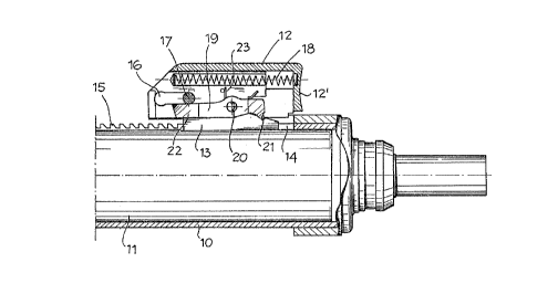
Said drawing shows a breech lU with barrel 10'
of a fire arm, e.g. an automatic gun, and with a
bolt 11 which is manually displaceable, by means of
a slider 12, from a front and closed position rest-
ing against the barrel to a rear and open position
defined by a tripping mechanism the moment in which
the arm is to be used.
Said slider 12 is assembled to the breech 11
through a support 13 which is fixed to the breech
and can thus be displaced together with it. Slider
1S 12 is assembled and guided on support 13 and sliding
in the direction in which the bolt is displaceable.
Support 13 is inserted into a longitudinal slot 14
cut into the breech 10 to allow the opening and
closing displacements of the bolt 11. At least at
one end of said slot 14 the breech 10 is fitted with
a sequence of teeth 15 sloping transversally to the
sense of displacement of bolt 11.
In support 13 a slot 16 which is parallel to
the axis of bolt 11 is provided to receive a pin 17
traversing the support 13 and thus the slider 12.
~'0~'~043
,....
- 5 -
Slot 16 and pin 17 cooperate in delimiting the slid-
ing motions of slider 12 on support 13 and taking
back said support with the bolt when the latter has
. to be manually taken into its open position. In the
illustrated embodiment said rearward displacement of
support 13 with bolt 11 is actually obtained by
placing the front end 12' of the slider against the
head of support 13.
Between support 13 and slider 12 a spring 18
is normally keeping the slider 12 displaced to the
front end of support 13, while the pin 17 is pushed
against the front end of slot 16.
In addition, on support 13 a rocking catch.
lever 19 is pivoted on a pin 20, said pin crossing
the direction in which bolt 11 is displaced. The
front end of said rocking lever 19, i.e. its end
directed towards the front end of the breech 10, is
fitted with a tooth 21 designed to interact, from
back to forth only, with the toothing 15 on the
breech, while its rear end 22 is designed to inter
act with pin 17, as will be explained here under.
Said lever 19 is also subject to a spring 23 to nor
mally keep its tooth 21 displaced towards the tooth
ing 15 and its end 22 towards pin 17 or to engage it
on said pin.
"._ , , , . .. . .
.=,:,:~.v~;,~.
> .; ~.~~
,
. . . ~ I~
_ 6 _ .
The operation of the safety device will now be
described by specifying some of its characteristic
operational stages.
W A. Arm in neutral position ,
In Figures 1 and 2 the arm is shown in its
neutral position: bolt ll is in its advanced posi-
tion and resting against the rear end of barrel 10';
the safety device is released.
~n particular, the position of the components
of said device, is:
- s~l.ide~ 12 is in its advanced position owing to
the
pressure exercised by spring 1~and f~ept in t~nia
position by pin 17 cooperating with. slot if ia~
support 13;
- catch tooth 21 of rocking lever 19 is- lifted above
the toothing 15 on breech 10; ands
- tail 22 of said lever 19 is. resting against pin
17
in slider 12.
B. Manual cocking , .
The first stage of manual cocking comprises a
pressure exercised in the direction of arrow F on
slider 12 to slightly displace it (by 10 mm approx.)
on its support 13 and thus in respect to bolt 11,
sLpport and Molt not moving during this first stage.
After that, when slider 12 has compressed the
T,:,~,:
2'00'043
_ 7 _
spring 18 like shown in Fig. 3, it is in such a
position that it disengages tail 22 of rocking lever
19 from pin 17 in the slider: now lever 19, pushed
by its spring 23, is able to move on till its front
tooth 21 is resting on the outer surface of breech
10, i.e. on its section comprising the toothing 15,
while its tail end 22 is level with pin 17 of the
slider.
While the manual cocking is continued', slider
12, after eliminating the space (10 mm approx.)
separating its front end 12' from the head of sup-
port 13, will start to actually push back bolt 11.
As shown in Figures 4 and 5, owing to spring
23, the front tooth 21 of rocking lever 19 is con-
stantly kept in contact with breech 10, while its
rear end 22 is at interacting level with pin 17. As
the backward motion is continued (see Fig. 6) catch
tooth 21 of lever 19 is travelling on the toothing
15 till the end of the cocking operation, i.e. till
bolt 11 is catched and fastened by the (not repre-
sented) tripping mechanism of the arm.
Before reaching this final condition of the
bolt allowing the actual use of the arm, some pos-
r
sibilities ought to be taken into consideratian.
B. Faulty move of the operator
2'00'043
If during manual cocking the operator acci-
dentally lets go the slider 12 or lets it go being
erroneously convinced it has reached its correct
position, he will bring about the situation shown in
5~ Figures 7 and 8. In fact, as the spring 18 of slider
12 is no longer compressed by the operator it will
extend and take slider 12 to its advanced position
on support 13. But by moving on slider 12 takes pin
1~ towards the tail end 22 of the rocking lever 19
which, as said before, is thus engaged by said pin.
In consequence, said rocking lever is obll.ged tQ
move in the direction of arrow G in Fig. T and thus
engage tooth 21 in the toothing 15 on breee~n 10 (see
Fig. 8). Lock 11 is therefore immediately stopped in
the position to which it has been displaced' and
where it has been abandoned, thus being absolutely
unable to reach its closed position.
The arm is thus in a static condition bf
partial opening of its bolt and at any rate in a
safe position, while the trigger is fully indepennt
from any motion of the bolt.
B.2 Continuation of the cocking operation (after an
eventual blocking as in B.1.)
As it can be seen in Fig. 8, it is not poss-
ible to act on the safety device to release it and
240'443
_ g _
allow the bolt 11 to advance towards the barrel 10'
into its closed position. In fact, any action exert-
ed on slider 12 in order to push on the bolt 11 will
only result in a tighter engagement of the catch
tooth 21 of rocking lever 19 in the toothing 15 on
the breech. Thus the only thing the operator can do
is to restart the manual cocking operation by grasp-
ing the slider 12 and push it backwards and when its
front end 12' is in tight contact with support 13 he
10~- will be able to move back the bolt till it is cor-
rectly engaged in the tripping mechanism.
B.3. Correct cocking (interception of the bolt by
the tripping mechanism).
It is now obvious that the operator is still
"obliged" to displaced the lock towards the tripping
mechanism, as otherwise he will by no means able to
use the arm for shooting.
On the other hand, the safety device is inac-
tivated only with the bolt engaged in the tripping
mechanism. To this purpose a release plate 24 is
fitted on the breech 11 after the rear end of
toothing 15, said plate 24 interacting with the
locking lever 19 so as to lift and displace it into
its neutral position as soon as the bolt has reached
its correct cocked position. The interaction of the
200'043
- 10 -
release plate24 with the rocking lever 19 is shown
in Fig. 9 the drawing where can be seen how,
of it
on one hand,the catch tooth of lever 19 is
21
displaced by plate 14 - arrow H - above toothing 15
and, on the other hand, tail 22 of said lever is
situated below pin 17 of slider 12.
That is why, once the slider is no longer
subject to the manual traction of the operator, it
is pushed on by spring 18 and goes back to its rest
lp position - see arrow F - taking pin 17 against the
top part of the tail end 22 of lever 19, thus keep-
ing said lever out of action (as it was at the be-
ginnig of the manual cocking operation (see Fig.2).
Now the arm is ready for shooting both single
shots and automatically, while the safety device
stays totally inert but always ready to exert its
function as soon as the bolt of the arm has to be
cocked again.