Note: Descriptions are shown in the official language in which they were submitted.
`- 2007045
INTERIOR BAG FOR A CONTAINER
FIELD OF THE INVENTION
This invention relates to an interior bag for a
container, and more particularly to a container interior
bag to be fitted in a general-purpose container provided
with hinged door or doors adapted to permit conveyance of
cargo in and out therethrough and used for admitting a
particular article such as cereal for bulk shipment.
BACKGROUND OF THE INVENTION
In the transportation of cereals and raw materials
for industrial products such as, for example, granular
synthetic resins and particulate raw materials, there have
been used containers exclusively adapted for such special
kinds of cargo as mentioned above. Since these containers
accept only specified kinds of cargo, they encounter the
inconvenience that after they have been used in
transporting cereals, for example, they are returned empty
from the destinations to the points of origin. In today's
marine transport conducted on a large scale as in the
transport of cereals, the fact that empty containers are
transported constitutes itself a cause for immense
diseconomy and pose a serious hindrance to the reduction
in cost of transport.
In the circumstances, the practice of transporting
cereals in general-purpose containers intended primarily
for ordinary kinds of cargo has come to prevail in recent
years.
'~C
~,
2007045
--2--
BRIEF DESCRIPTION OF THE DRAWINGS
The present invention and problems with prior art
containers will become more fully understood from the
detailed description given herein with the accompanying
drawings which are given by way of illustration only, and
thus are not limitative of the present invention, and
wherein:
Figure 1 is a partially cutaway perspective view
illustrating an interior bag as used in a container for
holding a bulk cargo;
Figure 2 is a cross sectional side view schematically
illustrating the container of Figure 1, with the rear
doors opened and the bag consequently allowed to swell
out;
Figures 3A and 3B are respectively a cross sectional
side view and a partial perspective view illustrating the
prior art for preventing the swell of the interior bag;
Figure 4 is a perspective view illustrating a interior
bag as a first embodiment of this invention;
Figure 5 is a cross sectional side view illustrating
the interior bag as fitted in a container for holding a
bulk cargo;
Figures 6A and 6B are cross sectional side views each
schematically illustrating the essential part of the
typical interior bag mentioned above as held for actual
use;
Figure 7 is a partial magnified perspective view
illustrating supporting bars as fixed for actual use;
r~
2007045
Figure 8 is a perspective view illustrating another
typical interior bag as a second embodiment of this
invention;
Figures 9A and 9B are respectively a rear view and a
lateral cross section illustrating the bag of Figure 8 as
disposed for actual use;
Figure 10 is a perspective view illustrating a third
embodiment of the interior bag according to this
invention;
Figure 11 is a developed view of the rear surface part
of the interior bag of Figure 10;
Figure 12 is a cross sectional side view of the
interior bag fitted in a container and filled with a bulk
cargo;
Figures 13A and 13B are respectively a lateral cross
section and a horizontal cross section illustrating the
rear surface part of the interior bag disposed for actual
use;
Figure 14 is a perspective view illustrating yet
another typical interior bag as a fourth embodiment of
this invention;
Figure 15 is a developed view of the rear surface part
of the interior bag of Figure 14; and
Figure 16 is a horizontal cross section illustrating
the rear surface part of the interior bag as disposed fast
for actual use.
. !
~007a~5
FURTHER DESCRIPTION OF THE BACKGROUND OF THE INVENTION
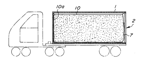
This utilization-of such general-purpose.containers
resorts to a method which, as illustrated in Figure 1,
comprises fitting in a container 1 an interior bag 4 made
of a sheet of such a resinous material as polyethylene in
a shape substantially identical with the internal contour
of the container 1 and stowing a cereal S in the interior
bag 4. In accordance with this method, when the
container, on completing the transport of the cereal, is
stripped of the interior bag 4, it resumes the original
form of an ordinary container and can be used on its
return course for the transport other kind of ordinary
cargo. This fact enhances the efficiency of use in a
large measure and lowers the cost of transport.
One fault found in this practice of using the
interior bag resides in the fact that when a weighty
granular or otherwise particulate cargo such as cereals is
placed in this interior bag, it lacks strength enough to
bear the weight of the cargo and consequently swells
outward as illustrated in Figure 2.
In the case of the general-purpose container, this
swell of the interior bag has its effect to bear on the
hinged doors in the rear part of the container, with the
possible result that the swell interferes with the opening
and shutting of the hinged doors and the inner pressure
~07~
(the pressure from the weight of cargo) causes the hinged
door to burst open when the hinged doors are unlocked.
As one way of preventing the interior bag,
particularly the rear face part thereof confronting the
hinged door, from swelling under the inner pressure, there
has been a method for precluding a rear surface 5 of the
interior bag 4 swelling by passing a multiplicity of
supporting bars 3 horizontally across a rear opening part
2 of the container 1 as spaced in the vertical direction
as illustrated in Figures 3A and 3B.
The method which resorts to the supporting bars 3
resides in utilizing grooves formed in the longitudinal
direction one each on the inner sides of vertical frames 6
erected upright as opposed to each other on the opposite
sides of the rear opening part 2 of the container (grooves
shaped by the formation of reinforcing ribs) for admitting
the opposite ends of the supporting bars 3 thereby
allowing the supporting bars 3 to be laid horizontally
across the opening part. The actual work involved therein
is easy because it is limited to that of fitting the
supporting bars in the grooves. When the cargo is a
weighty article such as cereals, the rear surface part 5
partially swells out beyond the supporting bars as
illustrated in Figures 3A and 3B and interferes with the
closure of the doors 7 serving to shut the opening part 2.
~007045
At the time that the doors are to be opened, the inner
pressure of the swell obstructs the doors from being
unlocked and entails the possibility of causing the doors
to burst open.
This swell of the bag could be eliminated by
increasing the number of supporting bars. The supporting
bars are generally made of a metallic material and,
therefore, their cost accounts for a relatively large
proportion of the total cost of the bag system. Since
these supporting bars are used only during the transport
of a granular or otherwise particulate cargo and are
useless after completion of the transport and are
cumbersome when the container is used for the transport of
other kind of cargo, they are destined to be discarded in
con;unction with the interior bag. The use of a large
number supporting bars has effect of increasing the
transport cost. The method of supporting the rear surface
part of the interior bag by using the multiplicity of
supporting bars has a disadvantage that, during the
unloading of the cargo, the bars obstruct the flow of the
cargo and renders difficult the work of unloading.
When the interior bag 4 is used in the general-
purpose container for transporting cereals, for example,
the loading is generally effected by causing 10-odd tons
of the cereals from a silo to be blown into the interior
"~ ~
2007045
bag through a duct in a matter of several minutes
(generally about 3 minutes). The unloading of this cargo
is effected by a method which comprises opening the hinged
door of the container 7, then forming an opening in the
rear face part 5 of the bag by inserting a horizontal slit
therein at a suitable position with a cutter, and
subsequently tilting the container 1 itself together with
the carrier vehicle backwardly thereby allowing the
cereals to flow out all at once through the torn opening.
If a large number of supporting bars 3 were used for
holding back the rear surface part of the interior bag,
these bars would obstruct the selection of a position for
the insertion of the slit restrain the torn opening to the
extent of obstructing the flow of the cereals.
Besides the problem described above, the conventional
interior bag entails the problem that when the torn
opening is formed and the container is tilted backward to
release the cargo, the interior bag slides backward in
conjunction with the cargo and inflicts breakage upon the
fastening devices attached to the container, particularly
those attached to the lower end of the front face part,
and the rear end of the bag out of the opening of the
container and interferes with the flow of the cargo or,
because of the slide, the bottom surface part of the bag
forms furrows which catch hold of part of the cargo,
2007045
interfere with the flow of the cargo, and prevent the
cargo from being smoothly released.
SUMMARY OF THE INVENTION
This invention has been perfected by research and
development conducted for the purpose of eliminating the
problems encountered by the interior bag to be used when
the general-purpose container intended primarily for the
transport of ordinary kinds of cargo is appropriated to
the transport of a granular and otherwise particulate
cargo. Accordingly, the invention seeks to provide a
container interior bag capable of decreasing the number of
supporting bars to be used for restraining the rear
surface part of the bag proper from the swelling in the
direction of the rear opening part of the container under
the inner pressure due to the weight of the cargo thereby
proportionately increasing the exposed surface area of the
rear surface part and, at the same time, effectively
curbing the swell of the rear surface part and enabling
the hinged door or doors closing the opening of the
container to be quickly and safely opened and shut.
This invention, in the light of the large addition to
the cost of transport by the inevitable use of the
plurality of supporting bars, aims to eliminate the impact
of the increased cost of transport by decreasing the
number of supporting bars and decrease the cost required
in diverting the general-purpose container to the
, ~ . .~,
i .. _,
'~` 2007045
transport of a particulate cargo and simplify the work
involved in the diversion.
Further, this invention seeks to provide a container
interior bag capable of smoothly releasing a bulk cargo by
avoiding the otherwise possible breakage due to the slide
of the bag when the container including the bag is tilted
for the discharge of the contained cargo.
The invention in one broad aspect provides an
interior bag to be fitted in a container, which comprises
a bag proper shaped in a substantially rectangular
parallelepiped having a front surface part, a rear surface
part provided in its upper part with a cargo inlet,
lateral surface parts, and a bottom surface part.
An auxiliary sheet has its upper edge attached to the rear
surface part of the bag proper at a level below the cargo
inlet of the rear surface part, which auxiliary sheet has
at least one tubular supporting bar fitting part and an
insertion piece extending below the lower edge of the rear
surface part to be inserted between the bottom surface
part of the bag and the bottom of the container, and at
least one supporting bar inserted in the at least one
tubular supporting bar fitting part and detachably secured
at its ends by the side frames of the container.
j ~
-
7a~s
-- 10 --
In accordance with the construction using this
auxiliary sheet, before the granular or otherwise
particulate cargo such as cereals is poured into the
interior bag, the aforementioned insertion piece portion
of the auxiliary sheet for tension is inserted beneath the
bottom surface part to the extent of causing the auxiliary
sheet to enclose the rear surface part as far as the lower
edge thereof and causing the rear part of the bottom
surface part to be drawn up. The portion contracted in
length due to the drag is immobilized in conjunction with
the insertion piece by the weight of the cargo introduced
in the interior bag. When the rear surface of the
interior bag swells under the inner pressure due to the
weight to the cargo, the auxiliary sheet is stretched taut
and enabled to prevent the swell from growing prominently.
In this construction of the auxiliary sheet adhesive
means capable of keeping the insertion piece infallibly
in the inserted state and, at the same time, facilitating
the fixation of the amount of insertion may be disposed in
the lower end part of the auxiliary sheet for tension
and/or in the bottom surface part of the bag proper.
Further, the upper end of the auxiliary sheet for
tension may be fastened to the rear surface part at a
-
2007045
level falling halfway along the height of the rear surface
part and, at the same time, the lower end part of the
- auxiliary sheet secured at a prescribed position on the
bottom surface part so that the rear part of the bottom
surface part may be contracted by a size prescribed as an
allowance for the aforementioned drag.
The auxiliary sheet may be provided on the opposite
sides in the roughly middle position thereof with
stretching belts which, by being stretched and fastened to
the lower end of the opening part of the container,
enables the auxiliary sheet draped over the rear surface
part of the bag to be kept desirably in a stretched state.
The interior bag may be further provided in the upper and
lower corner parts of the front surface part thereof with
stretching belts which, by being stretched taut inside the
container, serve the purpose of preventing the bag from
being snapped by the tension due to the slide of the bag.
As a result, the corners of the bag proper can be
protected against possible breakage.
The tension exerted on the rear surface part of the
bag may be effectively enhanced by causing the insertion
piece to be extended not only in the downward direction
below the rear surface part of the bag but also in the
lateral directions beyond the opposite sides.
These extensions of the insertion piece may be formed
- 2007045
by extending the auxiliary sheet laterally and downwardly
or may be separately formed and fastened to the lower edge
and the lateral edges of the rear surface part of the bag
proper.
Other aspects and characteristics of this invention
will become apparent from the detailed description to be
given hereinafter with reference to the accompanying
drawings.
DESCRIPTION OF PREFERRED EMBODIMENTS OF THE INVENTION
A first embodiment of the interior bag according to
this invention will be described hereinafter with
reference to Figures 4 to 7.
As illustrated, an interior bag proper 20 is formed
in the shape of a rectangular parallelepiped fitting the
inside dimentions of a container 1 and is provided at the
four corners on the front surface part 10a thereof and at
the two upper corners on the rear surface part 10b thereof
with suspending cords 11 adapted to be caught fast on
hooks (not shown) disposed in the inner corners of the
container and to keep the bag proper in a cubically
expanded state. The cords 11 are provided at the leading
ends thereof each an annular hook lla. Optionally, curved
hooks may be used instead as illustrated in the drawings.
The bag proper is formed of a sheet of synthetic
, ~
` Z00704~
- 13
resin such as polyethylene, or rarely close, similarly to
the conventional interior bag, so that the surfaces
thereof come into closs contact with the inner wall
surfaces of the container when the bag is fitted in the
container with the aid of the suspending cords 11. The
rear surface part of the bag opposed to the rear opening
part of the container 1 has the upper part 10c thereof cut
off a level falling halfway along the height of the rear
surface part to form a cargo inlet 12. The rear surface
part 1Ob below this level is prevented from rising
upwardly by having the opposite edges thereof sewn to the
rear edge parts of the opposite lateral surface part 1Od.
An auxiliary sheet 13 for tension formed in a roughly
uniform breath throughout the entire length is sewn along
the upper edge of the rear surface part 1Ob and is
consequently suspended along the outer surface of the rear
surface part.
The aforementioned auxiliary sheet 13 for tension is
formed with a sheet longer than the height of the rear
surface part 1Ob so that the lower end part of the
auxiliary sheet in the suspended state extends below the
lower edge of the rear surface part and gives rise to an
insertion piece 13a.
The auxiliary sheet 13 inclusive of the insertion
piece 13a encloses the rear surafce part substantially
~_ 200704~
_ 14
entirely and the insertion piece 13a is inserted beneath
the bottom surface part 10c. The auxiliary sheet 13 is
provided along the upper edge part and at a level falling
along the height thereof with tubular supporting bars 14
and 25 formed integrally with the sheet and laid in the
horizontal direction. Further, the insertion piece 13a is
provided on the inner surface thereof with adhesive tapes
17 attached fast as arranged in the direction of width of
the insertion piece 13a so as to be freely attached to and
detached from adhesive tapes 16 on the lower surface of
the bottom surface part 10 of the bag proper.
The adhesive tapes 16, 17 are intended to establish
fast union between the insertion piece 13 of the auxiliary
sheet 12 and the bottom surface part 16e when the
insertion piece 13a is inserted beneath the bottom surface
16e and prevent the auxiliary sheet from randomly slipping
out and to serve as marks for determining favorably the
allowance for the insertion of the insertion piece 13a.
In the present embodiment, the tapes are disposed either
intermittently or continuously throughout the entire width
of the pertinent parts.
Incidentally, in the present embodiment, the adhesive
tapes 16 on the bottom surface part side are positioned
slightly in a recess of the length of the insertion piece
13a in the inserted state as illustrated in Figures 6A and
,,
200~04~
6B so that when the adhesive tape 17 of the insertion
piece 13a joined thereto, the amount of this insertion of
the insertion piece is increased and the rear part of the
bottom surface part 1Oe is automatically drawn up inwardly
and, as a result, the lower end of the rear surface part
1Ob is drawn inwardly (Figure 6B).
In one other embodiment of this invention, though not
illustrated, the upper edge part of the auxiliary sheet 13
for tension to be draped on the rear surface part 1Ob of
the bag proper may be sewn to the rear surface part and
consequently attached integrally thereto and, at the same
time, the insertion piece 13a suspended along the rear
surface part may be drawn out under the bottom surface
part 10c so as to pull the rear part of the bottom surface
part forwardly and immobilize the insertion piece against
the bottom surface part where the length is contracted,
with the result that the auxiliary sheet causes a
contraction of the length of the bottom surface part in
the longitudinal direction of length and an inward drag of
the lower end of the rear surface part 1Ob in concert with
the contraction.
Since the interior bag of this invention is so
constructed as described above, the use thereof is
attained by first suspending the interior bag inside a
given container with the aid of the suspending cords, then
,,
,.. ,.. ,. -;
200704~
inserting the supporting bars in place, passing the
opposite ends of the supporting bars 3 into the suspending
rings 13 hung down from longitudinal frames erected
upright on the laterally opposite of the opening part 2 of
the container as illustrated in Figure 7, and suspending
the supporting bars 3 at prescribed heights.
After the rear surface part 1Ob and the auxiliary
sheet 13 have been suspended and supported in place at the
positions by the fixation of the supporting bars, the
insertion pieces 13a of the auxiliary sheet 13 is inserted
beneath the bottom surface part 1Oe and, at the same time,
the adhesive tapes are joined mutually. In this case,
when the insertion piece 13a of the auxiliary sheet 13
fixed in place in advance as by being sewn to the stated
position of the bottom surface part, the setting of the
interior bag is completed by the work of suspension with
the supporting bars.
After the interior bag has fitted closely inside the
container as described above, the granular or otherwise
particulate cargo such as cereals is stowed in the
interior bag through the cargo inlet adapted to open
toward the opening part of the container in the same
manner as in the conventional interior bag.
When the cargo is piled inside the interior bag as
the result of the loading described above, the weight of
,~
, .. ,, .................................................... -
Z00704~
- 17
the cargo presses the bottom surface part 1Oe and, by this
pressure, the insertion piece 13a of the auxiliary sheet
inserted thereunder is pressed and consequently nipped
between the interior bag and the floor surface of the
container. The insertion piece thus nipped is prevented
by the frictional force from being pulled out. As the
piling of the cargo further advances until the weight of
the cargo exerts inner pressure upon the rear surface part
1Ob, the auxiliary sheet whose insertion piece 13a is
inserted beneath the interior bag is tensed so much as to
prevent the rear surface part 1Ob from swelling out. As a
result, the otherwise inevitable protrusion of the rear
surface part in the direction of the opening part is
precluded.
An interior bag measuring 5,800 mm in length, 2,300 mm
in width, and 2,170 mm in height and provided with an
auxiliary sheet of the description given above was tested
to evaluate the effect of this invention. The results of
the test indicate that interior bag fulfilled its effect
sufficiently and the insertion piece produced sufficient
frictional force when the insertion piece 13a was given a
length of about 800 mm and that the interior bag was
consequently allowed to keep its tense state without
requiring any adhesive device and prevent the rear surface
part 1Ob thereof from swelling out. In the test, the
,~
200704~
- 18
length of the rear surface part 1Ob was 1,800 mm and that
of the upper surface part 10c was 900 mm. It was
confirmed by the test that infallible retention of the
insertion piece beneath the interior bag was obtained when
the length thereof was approximately in the range of 500
to 1,000 mm.
Now, a working example of the interior bag of this
invention will be described below. Generally, the loading
of cereals are effected by a method of blowing which uses
compressed air. In the case of a container having a
loading capacity of 20 kilotons, it is normal for about 17
to 18 kilotons of the cereal to be loaded therein a matter
of about 3 minutes.
The cargo blown into the bag by the compressed air
brings to pile up from the leading end side of the inside
of the interior bag and the pile continues to grow
backwardly inside the interior bag until it reaches the
rear part of the bag. The cargo consequently filling the
bag presses the portion of the bottom surface part 10c
contracted in length by the drag and participates in
compressing and immobilizing the insertion part 13a of the
auxiliary sheet 13. Then, the pile further grows finally
to the extent of pressing the rear surace part 1Ob.
In the interior bag of this embodiment, since the
auxiliary sheet 13 draped over the outer surface of the
,~
2~)0704~
- 19
rear surface part 1Ob is disposed as stretched taut in
advance and is deprived of any allowance for further
extension, and besides, since the rear surface part 1Ob of
the bag urged by the pressure of the cargo presses the
stretched auxiliary sheet and prevents it from producing a
motion, the possible swell of the rear surface part 1Ob
caused by the weight of the cargo is perfectly prevented.
Thus, the rear surface part is effectively prevented from
protruding outwardly beyond the opening part 2 and
interfering with the opening and shutting of the door 7.
From the interior bag of this invention in which the
cargo has been loaded as described above, the cargo is
unloaded by opening the door, then inserting a horizontal
tear in the rear surface part 1Ob at a level close to the
lower end thereof together with the auxiliary sheet 13 by
the use of a cutter, and subsequently tilting the
container proper backwardly thereby allowing the cargo to
flow out of the container all at once by its own weight.
In this case, the collapse of the shape of the cargo
due to the inclination of the container proper causes the
interior bag to move backwardly. In the bag of this
invention, since the lower corners of the opposite sides
of the front surface 1Oa are fastened in place with
elastic belts 11, the interior bag elongates
proportionately to the slide of the bottom surface part
,~
Z00704~
- 20
1Oe (as indicated by a two dot chain line in Figure 4) and
absorbs the load exerted upon the fastening parts of the
bag and, after the release of the cargo, contracts and
returns to the home position and keeps the bottom surface
part 1Oe in a flat state. As a result, the bag proper
sustains no damage during the loading or unloading of the
cargo and the bottom surface part of the bag proper
retains no part of the cargo after the unloading because
the bottom surface part is stretched out into a flat state
in consequence of the decrease of the cargo. Thus, the
cargo can be released quickly and smoothly. When the
release of the cargo is effected by the inclination of the
container, it often happens that the cargo remains more
less on the bottom surface part. In this case, workers
engaging in the unloading are compelled to remove the
remaining cargo by shaking the bottom surface part 1Oe.
In the case of the interior bag of this invention, this
removal of the trapped cargo by shaking is attained easily
because the bag proper is fastened in place with the
elastic belts 11. And the shaking be efficiently carried
out because the expansion of the belts permits a slight
longitudinal movement of the bottom surface part.
In this invention, when the elastic belts serving to
keep the front end part of the bag proper in place is slid
backward in conjunction with the cargo owing to the
,~
200704~
inclination of the container, the heavy burden exerted
upon the parts keeping the bag fast is absorbed by the
elongation of the elastic belts. Unlike the conventional
interior bag, therefore, the belts are not snapped or the
bag itself is not broken under the large burden mentioned
above. When the unloading of the cargo advances, the
particulate cargo is not trapped inside the interior bag
but is discharged smoothly because the bag is allowed to
resume its original shape and the bottom surface part of
the bag is enabled to resume its original flat shape by
the contracting force of the belts. The fact contributes
much to the enhancement of operational efficiency of the
unloading.
In the case of a cargo which is not readily allowed
to flow out by the inclination of the container, the fact
that the bottom surface part is allowed to resume its flat
shape by the contraction of the belts proves to be
convenient because the work of shaking the bag can be
carried out very simply as a consequence.
In accordance with this invention, the rear surface
part can be prevented from swelling out and the necessity
for using many supporting bars can be obviated owing to
the stretching force of the auxiliary sheet 13 provided
with the insertion piece 13a as described above. As a
natural consequence, the work of opening and shutting the
. .
Z00704~
- 22
hinged doors of the container can be facilitated and the
interior bag is not suffered to exert a strong inner
pressure upon the doors and the otherwise inevitable
possibility of the doors being burst open can be
precluded. Thus, the doors can be opened and shut quickly
and safely.
Then, the decrease in the number of supporting bars
to be used for the interior bag results in a reduction in
the cost of transport and a proportionate addition to the
area of the rear surface part left open and accordingly
facilitates the selection of a position in the rear
surface part for the formation of an opening by the
insertion plece of a tear with a cutter at the time of
unloading of the cargo. Moreover, the size of this
opening is allowed to be simply large. Further, the
decrease in the number of supporting bars results in
facilitating the work of fitting the opposite end parts of
the supporting bars in the grooves of the vertical frames.
Consequently, the work of fitting the interior bag in the
container can be easily and quickly carried out.
In another typical interior bag as the second
embodiment illustrated in Figures 8 and 9, the rear
surface part is enabled to produce a more effective tense
state by attaching a stretching belt 21 provided at the
leading end thereof with hooks 22 to the auxiliary sheet
,~
... ... .
Z~:)0704~
- 23
13 at a level falling halfway along the height thereof in
addition to making use of the stretching action exerted by
the insertion piece 13a upon the rear surface part of the
bag. In short, the rear surface part of the bag is given
a desirable tense state by setting the hooks 22 fast on
supports 23 disposed in the lower corners of the rear ends
of the lateral walls 1a of the container.
In the diagrams, the reference numerals which have
equivalents in the diagrams of the embodiment mentioned
above denote identical or equal component parts. The
description of these component parts is omitted below to
avoid repetition.
In the illustrated embodiment, a pair of stretching
belts 21 for exerting tension upon the auxiliary sheet 13
are symmetrically disposed as opposed to each other.
Optionally, a plurality of such stretching belts may be
disposed on each of the lateral sides. Of course it is
otherwise permissible to dispose these stretching belts
along the center between the opposite sides and allow them
to stretch the auxiliary sheet by being set fast against
the lower edge of the opening part directly below.
Particularly the embodiment having such stretching
belts disposed one each on the lateral sides so as to be
elongated in downwardly diverging directions is aimed at
efficiently enhancing the effect of stretching in addition
,~
.,.. ~,,.,,.. , ~,
200704~
- 24
to simplifying the construction as a whole.
It is clear from the embodiments noted above that
since this invention consists essentially in effectively
stretching the rear surface part of the interior bag by
the action of the insertion piece, the tension of the rear
surface part of the bag can be attained more effectively
by integrally extending from the opposite lateral edges of
the auxiliary sheet 13 such insertion pieces 13b adapted
to be inserted between the lateral surface parts 1Od of
the bag and the lateral walls 1a of the container as
illustrated in Figures 10 to 13 in addition to resorting
to the insertion pieces 13a adapted to be inserted beneath
the bottom surface part 1Oe of the bag.
In this third embodiment, the interior bag 10 loaded
with the cargo bears the weight of the cargo on the bottom
surface part 1Oe thereof and this weight presses the lower
insertion piece 13a inserted thereunder against the bottom
surface of the container and consequently fixes this
insertion piece 13a between the bag and the container.
Since the area of application of this pressure expands
laterally with the advance of the loading of cargo, the
same fixing action as mentioned above has its effects to
bear on the lateral insertion pieces 13b which are along
the outer lateral surfaces of the lateral surface parts,
with the result that the opposite insertion pieces are
,.. .. .
Z~)0704~
- 25
immobilized in the inserted state.
When the insertion pieces 13a, 13b mentioned above
are set fast in place as draped on the lower surface part
1Oa and the lateral surface parts 1Od of the bag and
nipped between the surface parts 1Oe and the wall surfaces
10 1a of the container, the insertion pieces 13b may be
provided with fastening devices 25 and tacked to the
lateral surface parts of the bag by setting these
fastening devices 25 to the fastening devices disposed in
advance on the lateral surface parts.
When the cargo accidentally exerts an inner pressure
on the rear surface part, for example, these insertion
pieces 13a, 13b readily cancel the fastened state and
prevent the bag proper from sustaining breakage. Of
course, these fastening parts are adapted to be readily
broken under the impact of the accidentally exerted inner
pressure when the free edges of these insertion pieces are
immobilized in advance as by fastening, for example.
An interior bag of this embodiment was produced for
in a 20-ton general-purpose container by preparing a bag
proper measuring 5,800 mm in length, 2,300 mm in width,
and 2,170 mm in height and attaching the insertion pieces
13a, 13b both of a length of 100 mm to the bag proper.
This interior bag was put to use, with the insertion
pieces inserted to a length of 200 mm, for the transport
2007045
- 26
of cereals. The rear surface part was infallibly
prevented from swelling out and was not suffered to
protrude to the extent of impinging on the hinged doors
serving to keep the rear opening of the container shut.
In the aforenoted third embodiment, the insertion
pieces 13a, 13b were integrally formed with the auxiliary
sheet 13 so as to assume an approximate shape or the
letter T as illustrated in the developed diagram of
Figure 11. Optionally, these insertion pieces may be
formed independently of one another and attached as draped
over the lower edge and the opposite lateral edge of the
rear surface part 1Ob of the bag as in the fourth
embodiment illustrated in Figures 14 to 16.
To be specific, the lower insertion piece 13a is
attached fast to the lower edge of the rear surface part
10b of the bag and the lateral insertion pieces 13b
attached fast one each to the opposite lateral edges of
the rear surface part 1Ob of the bag.
In this embodiment, the lateral insertion pieces 13b
are formed each in a substantially trapezoid shape. It is
of course permissible to form in a rectangular shape
similarly to the lower insertion piece 13a or in some
other shape selected freely.
The present embodiment can be expected to bring about
the same effect as the embodiment described above in spite
, ~
, "
200704~
- 27
of the omission of the auxiliary sheet. In this
embodiment, the lower and lateral insertion pieces 13a,
13b are jointly used. For the attainment of the effect
equivalent to that of the first embodiment, only the
insertion piece 13a may be used.
In the embodiments described above, like reference
numerals denote like or otherwise equal component parts.
In accordance with this invention, the rear surface
part of the bag proper is reinforced and prevented from
swelling out by the tension produced in the auxiliary
sheet immobilized by the pressure of the weight of the
cargo. Thus, the hinged doors of the container can be
closed easily and safely after the loading of cargo in the
container is completed and the doors can be shut similarly
easily and safely at the time of unloading of the cargo.
Further, since the interior bag of this invention has no
use for the supporting bars otherwise required to be
passed across the rear surface part at least below a level
halfway along the height thereof, the position for the
insertion of a tear with a cutter can be selected with
ample freedom and the tear itself can be formed in an
amply large size.
Moreover, the invention is advantageous in respect
that the consumption of supporting bars is generously and
the cost of transport is proportionately decreased. It
,~
200704~
also enjoys an advantage that the work of using the
interior bag in the container is notably alleviated
because the work of fitting the interior bag in the
container is simplified.
Obviously many modifications and variations of the
present invention are possible in the light of the above
teachings. It is therefore to be understood that within
the scope of the appended claims in the invention may be
practiced otherwise than as specifically described.
1 0