Note: Descriptions are shown in the official language in which they were submitted.
200~209
SPINAL STABILIZATION METHOD
BACKGROUND OF THE INVENTION
1 Field of the Invention
.
This invention pertains to surgical procedures for
stabilizin~ a spine. More particularly, this invention
pertains to a novel procedure with enhanced intervertebral
stabilization and reduced patient risk.
2. DescriPtion of the Prior Art
Chronic low back pain is one of the most common
and perplexing problems facing the field of orthopedic
surgery. In addition to the discomfort of the patient, low
back pain has severe adverse societal impacts. Ineffective
treatment of low back pain results in increased lost time
from work and increased insurance claims. Much more tragic
societal consequences arise from the pa~ient~s efforts to
cope with chronic low back pain. These include loss of
income or job, loss of self and family esteem, possible
chronic dependence on drugs, alcohol and public relief
programs.
In many cases, low back pain can be avoided if
relative motion between spinal vertebra can be prevented.
Immobilization (or, more commonly, intervertebral
stabilization) is sought in a wide variety of treatment
methods. To abate low back pain, stabilization is directed
to stabilizing contiguous vertebra in the lumbar region of
the spine.
2007209
While the following list is not exhaustive, it
illustrates prior stabilization techniques:
1. Non-Surqical Stabilization
The simplest stabilization is accomplished through
S use of back braces. The brace is worn externally by the
patient to restrict lumbar movement. Unfortunately, the
brace is bulky and uncomfortable and limited in its
effectiveness.
2. Surqical Stabilization
a. Generally
Low back pain is presently believed to be
associated with anatomic changes in the discs which separate
the lumbar vertebra. Surgical stabilization first
identifies the degenerated disc and seeks to rigidly join
the lumbar vertebra which are separated by the degenerated
disc. Ideally, the surgery effectively replaces the
vertebra-disc-vertebra combination with a single rigid
vertebra. Various surgical techniques have developed which
attempt to approach or approximate this ideal.
b. Anterior Spinal Interbody Fusion
The anterior route for fusion involves a surgeon
seeking access to the spine through the front (i.e. stomach
area) of the patient. Exposure of major organs and blood
vessels is required. Accordingly, due to difficulty and
danger, this method has not received wide-spread acceptance.
2007209
c. Posterior Interbody Fusion and Postero-
Lateral Fusion
Posterior fusion means access to the spine is
achieved through the back of the patient. Postero-lateral
fusion is similar with access coming more from either or
both sides of the patient. Several posterior or postero-
lateral techniques are known.
i. Usual Sinqle Level Postero-Lateral
Fusion
The usual inter-transverse process fusion involves
bone grafts connecting the transverse processes of
contiguous vertebra. The transverse processes are bone
portions extending radially away from opposite sides of the
vertebra body. The grafted bone is commonly taken from the
iliac crest.
The inter-transverse process fusion has several
drawbacks. Gross destruction of normal anatomy is required.
2~ Also, a significant incision is necessary to expose a
sufficient area of the lumbo-sacral area in order to perform
the surgery. This wide exposure results in high blood loss
and significant muscle and bone destruction.
An additional drawback of this technique is that
the fusion requires a significant time to become solid. For
example, fusion may require nine to twelve months. During
this period, the spine is rendered less stable than it was
before the operation.
A further disadvantage of this technique is that
2007209
the fusion occurs between the transverse processes which are
spaced from the body of the vertebra. Accordingly, complete
stability is not achieved.
ii. Dowel-Type Interbody_Fusion
A dowel technique for a posterior interbody fusion
is known. In the dowel technique, a bore hole is formed
through the degenerated disc area. The diameter of the bore
is sized so that cutting takes place both into the disc and
the opposing surfaces of the vertebra body. With the bore
formed, bone dowels are placed within the bore. If
successful, fusion occurs between the bone dowels and the
opposing surfaces of the vertebra body.
The dowel-type technique is limited in
effectiveness. The size of a bore which can be directly
formed into the spine is limited by the access area to the
spine. Namely, the vertebra structure, location of the
spinal cord, location of important nerves and blood vessels
restric~ the eEfective maximum size of the bore which can be
formed. ~s a result of this restriction, the amount of
degenerative d:isc material which can be removed is limited.
Also, the surf~sce area of the vertebra body which is exposed
and available Eor grafting is limited.
iii. Graftinq ~nto A Cleaned Interbody Space
This technique requires removal o~ the degenerated
disc. The degenerated disc is removed through chiseling or
the like to clean the interbody space. When the interbody
2007209
spaced is exposed, large bone segments are placed into the
space and grafted to the opposing vertebra. This
technique has enjoyed a high percentage of s~ccessful
interbody fusions. However, the procedure is very difficult
to perform requiring three to six hours by experienced
surgeons. Also, the process of removing the disc exposes
major nerves and blood vessels to damage. Due to the danger
associated with this technique, it is in limited use.
iv. Need for Improved Techniques
As noted above, there are many techniques for
stabilizing vertebra. However, these techniques have
individual drawbacks. Due to the extreme economic and
sociological impact of chronic low back pain, a need for
improved techniques with high effectiveness and decreased
risks has long persisted and been sought in orthopedic
surgery. However, techniques which meet the dual goal of
high fusion with low acceptable risks have evaded the art.
SUMMARY OF THE INVENTION
According to a preferred embodiment of the present
invention, an improved method for vertebra stabilization is
disclosed. The method involves forming a bore into the
degenerative disc area with the bore sized for an initial
cutting tool to have access through the patient's anatomy.
A surgical tool is inserted into the bore with the tool
having a distal end which is received within the bore. The
2007209
distal end carries retractable cutting blades. Operation of
the tool reams an enlarged cavity on the interior of the
opposing vertebra bodies and removes the degenerative disc
material. When the enlarged interior cavity is formed, the
tool is retracted. The cavity is filled with a graft medium
which grafts with the opposing vertebra to form a suitable
fusion.
BRIEF DESCRIPTION OF THE DRAWINGS
Fig. 1 is a posterior view of a segment of a
lumbar spine with a graft made according to the prior art
technique;
Fig. 2 is a lateral view of a spinal segment
showing a prior art fusion technique;
Fig. 3 is a posterior view o~ the fusion technique
of Fig. 2;
Fig. 4 is a perspective view of a spinal segment
showing a prior art fusion technique;
Fig. 5 is a perspective view of a surgical tool
according to the present invention;
Fig. 6 is a top plan view of the tool of Fig. 5;
Fig. 7 is the view taken along lines 7-7 of Fig 6;
Fig. 8 is the view taken along lines 8-8 of Fig.
6;
Fig. 9 is the view of Fig. 6 with a control
mechanism removed;
2007209
Fig. 10 is an enlarged view of a distal end of the
tool of the present invention;
Fig. lOA is a view of an interior end of a central
rod of the tool of Fig. 5;
S Fig. 11 is a cross-sectional view taken of the
tool of Fig. 5 section showing blades disposed within a
first position or retracted;
Fig. 12 is the view of Fig. 11 showing the blades
in a second or extended position;
Fig. 13 is a view of a first blade for use in the
present invention;
Fig. 14 is a view of a second blade for use in the
present invention;
Fig. 15 is a view showing a possible positioning
of the tool of the present invention during operation;
Fig. 16 is a lateral view showing positioning of
the tool of the present invention;
Fig. 17 is a sectional view of a bore and chamber
shown in perspective in a spine;
Fig. 18 is the view of Fig. 17 without the view
being taken in section;
Fig. 19 is a sectional view taken in perspective
of an access bore formed in a spine;
Fig. 20 is the view of Fig. 19 showing the access
bore enlarged by a tool of the present invention;
Fig. 21 is a view showing alternate positioning of
2007209
the tool of the present invention;
Fig. 22 is a view of a spine showing relative
dimensions of spinal elements and a bore made according to
the present invention; and
Fig. 23 is the view of Fig. 17 showing a graft
medium in the enlarged chamber.
DESCRIPTION OF THE PREFERRED EMBODIMENT
A. The Prior Art
1. Transverse Process Fusion
_ _ _ _ _
Before proceeding with the detailed description of
the preferred embodiment, a more detailed description of the
prior art will be given with reference to the drawings. It
is believed such a description will~facilitate the reader~s
lS understanding of the apparatus and method of the present
invention.
Referring to Fig. 1, the prior art technique of an
intertransverse process fusion is shown. Fig. 1 is a
posterior view (i.e., taken through the patient's back) of
three lumbar vertebra 10, 10' and 10''. Each of vertebra
10-10'' includes a body portion lOa-lOa'' and a pair of
laterally projecting bones known as transverse processes
lOb-lOb'' and lOc-lOc''. Also, each vertebra includes a
posterior projecting bone known as the spinal process lOd.
The vertebra body lOa, lOa' and lOa'' are separated by
spinal discs 12 and 12'.
2~)07~09
In the view of Fig. 1, disc 12 is a diseased disc
which contributes to relative instability between vertebra
10 and 10''. To effect stabilization, bone segments 14 are
taken from the iliac crest (not shown) and grafted onto
vertebra 10 and 10'' with the grafted bone 14 extending
between opposing transverse processes lOc, lOc'' and lOb,
lOb''.
In order to perform a transverse process fusion, a
surgeon must make an incision in the patient's back and
separate tissue and muscle in order to expose the wide area
in which the grafting is to take place. This results in
gross destruction of normal anatomy as well as high blood
loss. Also, this surgical technique does not completely
stabilize the vertebra since there is no direct connection
be~ween the vertebra body lOa and lOa''.
2 Dowel Interbody Fusion
.
The dowel-type interbody fusion referred to
previously is shown illustrated in Figs. 2 and 3. Fig. 2 is
a lateral view of the view of Fig. 3. In Fig. 3, only the
vertebra body portions lOa, lOa' are shown.
As shown in Fig. 3, two bores 16 are formed into
the diseased disc tissue 12. The bores 16 are made as large
as possible so that they also cut into the bone of the body
portions lOa and lOa''. The bore 16 is formed through
either open surgery or percutaneous surgery. In open
2007209
surgery, the surgeon makes an incision and separates tissue
and muscle to expose a wide area of the spine before
drilling the bore 16. In the percutaneous method, a small
incision is formed and a guide tube is placed against the
desired location of tissue 12. The drill bit is based
through the guide tube to drill bore 16.
Bone dowels 18 are inserted within the bores 16.
In Figs. 2 and 3, the size of the gap between the bore 16
and the dowel 18 is exaggerated solely for purposes of
illustration. In practice, the dowel 18 is made to fit as
snugly into the bore 16 as possible.
The technique shown in Figs. 2 and 3 is limited.
The bore 16 is drilled through use of commercially available
surgical drill bits. There is a limit on the maximum size
of the diameter of bore 16 for any given patient. The limit
is attributed to the fact that too large of a drill bit
cannot be passed through the patient's body and placed
against tissue 12. If too large of a drill bit is used, the
size of the bit will interfere and possibly damage other
anatomical parts such as important blood vessels, nerves,
etc. Due to this restriction only a limited amount of the
disease disc tissue 12 is removed. Also, the portion of
opposing surfaces of body portions lOa, lOa' which can be
removed by the drill bit is limited. This limits the
surface area of the graft. This limitation adversely
impacts on the potential success of the graft.
2007209
3. Graftinq In Vacated Intervertebral Space
A third prior art method for interbody fusion is
shown in Fig. 4. In this method, the surgeon cleans away
all tissue between the vertebra to be fused. As a result,
all disc tissue 12 as well as disc plates ~not shown) are
removed. Large surface area bone grafts 2~ are placed
within the clean space to form a graft between the opposing
vertebra bodies.
The technique of Fig. 4 requires fairly complete
cleaning of the disc tissue and plates between the vertebra
to be fused. ~his is a time consuming procedure which
presents hazard to major nerves and blood vessels in the
area of the vertebra. As a result of these risks, this
procedure is frequently avoided.
B. Novel ~pparatus
-The method of the present invention is preferable
practiced using a novel tool. To facilitate understanding
of the method, the structure of the novel surgical tool will
now be described.
1. Main Body
Reference is now directed to Figs. S through 14 in
which identical elements are numbered identically
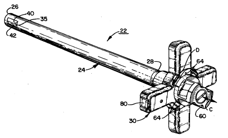
throughout. Fig. S is a perspective view of the surgical
tool 22 of the present invention. Tool 22 includes an
elongate cylinàrical shaft 24 having a distal end 26 and an
operator engaging end 28. Fixedly connected to the shaft 24
2007209
at end 28 is a handle 30. As will be more fully described,
the diameter of shaft 24 at distal end 26 is sized such that
shaft 24 can be inserted into a patient's body with distal
end 26 placed against a diseased disc without shaft 24
having undue interference with other anatomical organs.
Shaft 24 is hollow. As best shown in Figs. 7-lOA,
an interior rod 32 is coaxially disposed within shaft 24 and
mounted therein for rotational movement about axis X-X. Rod
32 has an exterior end 33 extending axially beyond handle
30. Additionally rod 32 has an interior end 34 (shown in
Figs. lO and lOA) disposed adjacent distal end 26.
Extending in an axial direction from end 34 are a
pair of parallel spaced apart eccentric pins 36, 37 which
project off the axial face of end 34 and are spaced from the
axis X-X of rotation of rod 32. An end cap 27 covering
distal end 26 has an internal annular groove 28 which
receives the free ends of pins 36, 37.
2. Cuttinq Blades
Distal end 26 is provided with a slot 35 extending
therethrough. Received within slot 35 are cutting blades 40
and 42 (shown best in Figs. 11-14). Each of blades 40, 42
is provided with a blade body 41, 43. Bodies 41, 43 are
similar in that each have an arcuate first end 44, 46 and an
opposite cutting edge 47, 48.
Spaced between arcuate edges 44, 46 and cutting
edges 47, 48 are bores 49, 50 extending parallel to edges
2007209
44, 46. Bores 49 and 50 are elongated in cross-section and
are sized to receive eccentric pins 36, 37. Shown best in
Figs. 12 and 13, the longitudinal cross-sectional dimension
of bores 49, 50 extend generally perpendicular to the
dimension extending between arcuate edges 44, 46 and cutting
edges 47, 48. Shown best in Fig. 12, blades 40, 42 include
flat opposing surfaces 51, 52 and opposite flat surfaces 53,
54 which oppose internal flat surfaces 55, 56 of distal end
26.
Blades 40, 42 are sized such that when received in
slot 35, blades 40, 42 are slidable relative to one another
with surface 51 engaging surface 52 in sliding engagement.
Further, surface 53 slidably engages surface 55 and surface
54 slidably engages surface 56.
The blades are slidable relative to one another
between a first, or retracted, position (shown in Figs. 5
and 11) and a second, or extended, position (shown in Figs.
12 and 16). When in the retracted position, the blades are
completely received within the external dimensions of the
distal end 26. Arcuate ed~es 44, 46 have a radius of
curvature the same as that of distal end 26 such that they
conform with the external dimensions of distal end 26.
Blade edges 47, 48 are completely received within the distal
end 26.
When shaft 34 is rotated counterclockwise (when
viewed in Fig. 11), pins 36, 37 rotate within bores 49 and
2~07r'03
50. The cooperation of the eccentric pins and the bores
translates rotational movement of shaft 32 into lateral
movement of blade 40, 42 in the direction of the arrows A
and B. A 45 rotation of the shaft fully extends the blades
to the position shown in Fig. 12. To retract the extended
blades, shaft 32 is rotated clockwise (when viewed in Fig.
12).
3. Cuttin~ Blade Control
A control mechanism is provided for controlling
the amount of extension of the blades 40, 42 and to hold the
blades in a desired extended position. The control
mechanism includes an adjustment grip 60 carried on exposed
end 33 of rod 32.
Shown best in Fig. 7, grip 60 includes a pair of
pins 62 opposing handle 30. Pins 62 are sized to be
received within any of a plurality of circumferentially
spaced holes 63 formed on the surface of handle 30. Holes
63 correspond with positioning of blades 40, 42. For
example, with pins 62 received within holes 63a, blades 40,
42 are fully received within distal end 26 as shown in Fig.
11. With pins 62 received within holes 63b, blades 40, 42
are fully extended as shown in Fig. 12. Indicator grooves
64 extend radially away from holes 63 so that a surgeon can
sight check the extension of blades 40, 42.
Shaft 32 is rotationally locked to grip 60 by
means of free end 33 having a triangular cross-section (best
14
2007209
shown in Fig. 9) which is received within a complimentarily
cross-section opening 65 (see Figs. 7, 8) of grip 60. Grip
60 may slide axially on free end 33 (in the direction of
arrow C in Fig. 7) such that pins 62 may be removed from
holes 63 and the handle rotated (in the direction of arrow D
in Fig. 7) to any one of a plurality of angularly displaced
position with pins 62 reinserted within holes 63.
4. Lock Mechanism
Once inserted into desired position, pins 62 are
retained within the desired holes 63 by means of a
releasable lock structure 70 (shown best in Figs. 7, 8).
The lock structure 70 includes a retaining cup 72 secured to
an axial face of free end 33 by means of a screw 73. Cup 72
is spaced from free end 33 with the space sized to
accommodate a spring 74. One end of spring 74 abuts cup 70
and the other end of spring 74 abuts an inwardly projecting
flange portion 61 of grip 60. Accordingly, grip 60 is urged
against handle 30 by means of the urging of spring 74.
To move the pins 62 between other positions, an
operator engages grip 60 and forces it in the direction of
arrow C against the urging of spring 74 with the operator
then rotating both grip 60 and shaft 32 in the direction of
arrow D to the desired angular displaced position. The
operator releases the grip 60 and the spring 74 urges the
pin 62 into the proper hole 63. A threaded hole 75 is
formed through the grip 60 to expose screw 73. A threaded
2007209
cover 76 is provided for closing hole 75.
5. Axial Positionina Of Shaft
Shaft 32 can be removed from time to time in order
to change or sharpen blades 40, 42. To assemble the
apparatus, blades 40, 42 are inserted within slot 35 in the
position shown in Fig. 11. To align pins 36, 37 with bores
49, 50, an alignment block 76 (see Figs. 7, 9) is formed on
shaft 32. Alignment block 76 conforms with a hole 77 formed
on handle 30. With block 76 and hole 77 aligned, pins 36,
37 are aligned with bores 49, ~0. The shaft 32 can then be
axially slid into position with the pins received within the
bores. To hold shaft 32 in axial alignment, a retaining
plate 80 is provided which is sized to be received within an
annular groove 81 formed in shaft 32 (best shown in Fig. 8).
Alignment plate 80 is held in fixed position by means of a
threaded retaining member 82 threadedly received within
handle 30.
6. Alternative Cuttinq Blade Desiqn
Shown best in Figs. 13 and 14, blades 40 and 42
are provided with complimentary cutting edges 47, 48.
Namely, the peaks 47a of cutting edge 47 are aligned with
the troughs 48b of cutting edge 48. Similarly, the peaks
48a of cutting edge 48 are aligned with the troughs 47b of
cutting edge 47. As a result, the cooperative cutting
action of blade edges 47, 48 form a generally cylindrical
hole. It will be appreciated by those skilled in the art
21~)07209
that the cutting edges 47, 48 can be adapted such that a
wide variety of geometries can be given to a final hole t~
be cut by the blades. For example, cutting edges 47, 48
could be arcuate (rather than generally linearly) to form a
generally spherical hole.
. Method of the Invention
The method of the present invention involves use
of the novel apparatus 22 to form a chamber in a spine for
receiving a graft medium.
1. Open Method
a. Expose Area And Locate Drill Site
The present invention can be used in both open and
percutaneous surgical methods. In the open method, the
spine is approached from the posterior of the patient using
local, spinal or general anesthesia. Using ~nown surgical
techniques, the diseased disc and adjacent vertebra are
exposed.
b. Drill Access Hole
With the spine exposed, a bore 100 is formed
through the disc layer 12 as shown in Fig. l9. The bore 100
is formed through any conventional means by using a surgical
drill bit (not shown). The bit is sized such that the
diameter of the bore 100 is approximately the size of the
external dimensions of distal end 26 of tool 22 so that
distal end 26 may be received within bore 100. The depth of
bore 100 is controlled so that distal end 26 can be fully
2007209
inserted between vertebra body lOa, lOa' (as shown in Figs.
15 and 16). Controlling depth of a bore hole in a spine is
well within the skill of the art.
c. Ream Cavity
With the bore formed, the distal end is inserted
within the bore. With distal end 26 completely received
within bore, the surgeon incrementally rotates handle 60 to
progressively increase the amount of extension of blades 40,
42. At each incremental extension, the surgeon rotates the
handle 30 completely about axis X-X so that the blades cut
out a large chamber 102 equal to the size of the diameter of
the extended blades (see Figs. 17, 18). After each such
cut, the handle 30 is incrementally turned to progressively
increase the diameter of the cutting edges of blades 40, 42
until a chamber 102 of desired size (up to the diameter of
the fully extended blades 40, 42) is formed.
Intermittently, between enlarging the diameter of the
enlarged chamber 102, the surgeon may op~ to fully retract
the blades 40, 42 and remove the tool 22 to flush the
chamber 102 being formed. Such flushing techniques are
known in the a.rt.
-d. Alternative Positioninq Of Chamber
Figs. 17, 18 shows an enlarged bore fully formed
within the interior of opposing vertebra bodies. An
alternative is to control the depth of the initial bore 100
such that the enlarged bore 102~ is formed flush on the
18
2007209
surface of the vertebra bodies as shown in Fig. 20.
e. Fillinq Chamber With Graft Medium
With the chamber 102 formed and the surgical tool
22 removed, the chamber 102 is filled with any suitable
graft medium 103 (see Fig. 21) such as finely chopped
cortical or cancellous bone chips. Upon filling the chamber
102 with the graft medium 103, the patient's wound is closed
through known surgical techniques.
2. Percutaneous SurqerY
In addition to the open method, the method of the
present invention with use of the novel tool of the present
invention may be used with a percutaneous surgical
technique. In the percutaneous method, the patient is
placed in a latexal position similar to that used during a
chymopapain installation. Local and intravenous anesthesia
is used so that the patient can report any symptoms or nerve
irritation during the procedure.
a. Locatinq Drill Site
The patient's skin is prepped and a plastic drape
is applied ancl the skin and soft tissues are infiltrated
with ~ one percent xylocaine. Under bi-plane fluoroscopic
control, a smooth guide pin (not shown) (preferably 2.5
millimeters in diameter) is carefully positioned to line up
with the diseased disc 12. The guide pin is driven into the
disc and a sheath (not shown) is fitted over the guide pin.
A locating cylinder 104 (see Fig. 16) is placed over the
2007209
sheath. A drill bit (not shown) is passed through cylinder
104 and a hole sized to receive the distal end 26 is drilled
into the intel~ertebral space. It will be appreciated that
forming a bore by drilling through a locating cylinder as
described is known in the art.
b. Forminq Enlarqed Chamber
With the access bore l~0 so formed, the distal end
26 is guided through the cylinder 104 into the bore. Fig.
16 shows shaft 22 being guided by a locating cylinder 104.
The tool 22 is used as described in the open surgery method
to produce an enlarged chamber 102 within the disc 12 and
surrounding bone lOa, lOa'. This chamber 102 is irrigated
from time to time by removing the tool 22 and flushing the
chamber 102. Extra xylocaine is injected as necessary.
lS c. Use Of Graf~ Medium
When the tool 22 has been used as desired to form
the chamber 102 of desired size, additional procedures may
be done at this time depending upon the needs of the
patient. For example, if a disc hernia is being treated,
the operation may be terminated at this point since the disc
has been effectively decompressed. If fusion is desired,
the cavity may be filled with finely chopped cortical or
cancellous bone chips impacting the chip to provide some
mechanical stability. The patient is then closed through
any known surgical techniques. The grafting of the bone
chips result in a fusion between the vertebra bodies.
2007Z09
d. Alternative Anqles Of Entry
Figs. 15 and 21 show possible angles of entry for
the tool when used in the method of the present invention.
In Fig. 15, the tool is shown inserted through percutaneous
method at an angle of about 75 relative to the anterior-
posterior axis, A-P, of the patient. It is believed this
angle is suitable for use at the space between the fourth
and fifth lumbar vertebra and above. As shown in Figs. 1~
and 16, the distal end 26 is completely received within the
vertebra body lOa. Fig. 21 shows alternate angles for
insertion of the tool with the size of the tool presenting
minimal interference or destruction to other anatomical
organs. In Fig. 21, line E shows an angle through the
laminar bone. In line F, access is through the soft tissues
of the lumbar paravertebral muscles. It is anticipated that
angle E represents a preferred angle for insertion in most
situations.
D. Size Of Tool
With best reference being made to Figs. 15, l~ and
23, important dimensions of the tool 22 with respect to
spinal anatomy will now be discussed. The dimensions of the
distal end 26 and cutting blades 40, 42 are selected with
reference to predetermined dimensions of the spine in which
the tool 22 is to be used. For example, ~or use in
operating on a human, the dimensions are preferably selected
2007209
with respect to known human vertebra size.
Illustrated best in Fig. 22, a typical
intervertebral space, S, between the fourth and fifth lumbar
vertebra body portions lOa, lOa' is shown. Intervertebral
spacing (i.e., the disc height, S) between vert2bra is
normally 10 millimeters (including disc cartilage and end
plates). The width, W (i.e. the dimension measured between
the sides of the vertebra), of the vertebra is about 45
millimeters. The depth, D (see Fig. 16) (i.e. the anterior-
posterior dimension of the vertebra) i5 about 35millimeters. Such dimension are typical for an adult human
male and may vary with the age and sex of the patient as
well as other factors. The dimension will also vary for
different locations in the spine.
To avoid interference of the distal end 26 with
other anatomical parts and to permit location of the distal
end 26 against disc 12, the distal end has a diameter of
about 12 millimeters. Accordingly, axis bore 100 (as shown
in Fig. 19) is preferably formed with a diameter of about 12
millimeters. A larger access hole would require the drill
bit which wou]d unduly interfere with other anatomical
parts. The thic~ness of the locating cylinder 104 results
in its diameter being about 15 millimeters (as shown in Fig.
22).
Cutting blades 40, 42 are selected such that in
the fully extended position, they cut an enlarged chamber
2007209
having a diameter of about 22 millimeters. As shown in Fig.
16, the length, L, of the cutting blades (and hence the
length of the chamber 102~ is shown as 25 millimeters so
that the blades can be fully received within the 35
millimeter dimension of the vertebra body depth D (Fig. 16).
When sized as described above, the rotation of the
distal end with the extended blades cuts both bone and
cartilage (See Figs. 17, 18, 20, 22). The surface area of
the bone is greatly enlarged beyond that which is cut by the
prior art boring technique. This greatly enlarged surface
area enhances the chances of successful fusion. The
diameter of the chamber is held at 22 millimeters so that a
~learance, CL, of about 11 millimeters is provided to
prevent possible cutting action through the exterior of the
spine which could damage important nerves or blood vessels.
The distal end 26 is sized to represent the bore
size 100 which could be made with prior art drilling
techniques. Namely, this is the size of a rod which can be
inserted towards the spine without interference with other
anatomical parts. The present tool effectively enlarges the
possible bore size through use of the retractable cutting
blades. This results in increased amounts of diseased
tissue being removed from the disc area and an increase
surface area of vertebra bone being exposed for grafting.
These dual enhancements cooperate to provide a more
effective graft.
23
2007209
The fore~oing dimensions and descriptions have
been given with respect to human anatomy. It will be
appreciated that the present tool and method could be used
on any animal spine. However, the dimensions of the tool
S will vary proportionately with increases or decreases in
spinal anatomy between different animal types. Also, in
humans, the dimension will vary with numerous factors
including anatomic region of the spine, age and sex. For
example, the tool and method is not limited to the lumbar
region and may be utiliæed in other regions of the spine
where vertebra dimensions may be different than those
illustrated. Therefore, several different sizes of the tool
22 is anticipated so a surgeon can select the optimum tool
for a given patient.
The size of the tool is selected for the distal
end 26 to be as larqe as possible while avoid undue danger
upon insertion. For an anticipated approach, a surgeon may
cut away a portion of the laminar portion of the vertebra.
The laminar portion is shown in Fig. 1 as item lOe'' and is
known as the plate-like portion of bone connecting the
spinal process lOd'' to the facet joints of the spine. For
a particular anatomical location, the distal end is sized to
permit passage through a partially cut-away laminar of
opposing vertebra without need to damage the facet joints.
Also, the size restriction of the distal end 26 recognizes
that there is a limit to which a surgeon may safely move
24
2007209
aside the cauda equina sac.
As previously noted, the enlarged bore can be left
vacated for the purposes of decompressing a herniated disc.
Alternatively, the chamber can be filled with a graft medium
S for the purposes of fusing contiguous vertebra. The graft
medium described above is bone chips or the like. However,
any graft medium (such as a bone dowel or a graft
prosthesis) could be used.
From the foregoing, it can be seen how the present
invention is attained in a preferred manner. Modifications
and equivalents of the disclosed concepts which readily
occur to those skilled in the art are intended to be
included within the scope of the invention. Thus, the scope
of-the invention is intended to be limited only by the
claims which are, or may hereafter be, appended hereto.