Note: Descriptions are shown in the official language in which they were submitted.
1 PONER ACTUATED ~EVICE FOR IN~TALLING ~T~L COR~ER_55RI~
BACR ~OUND OF TH~ INVEN~ION
This invention relates to a device for lnstalling
a protective corner strip along a corner formed by two
intersecting wall panels of, for example, ~heetrock or
gypsum board. More specifically, thi~ invention relates
to a hand held power actuated devlce usable for attaching
a protective corner strip to wall corners of dlffering
contour.
The outside corners of sheetrock or gypsum board
walls are customarily flnished by at~aching a metal strip
havlng a shape which complements the contour of such
cornere. After the strip ls attached to the wall it is
- covered with joint compound which, after hardening,
- 15 ~ubstantially conceals the protective strip.
The metal strip is sometlmes attached to the wall
by nailing, however, it is more often attached by forming
several indentatlons or crimps ln the side portlon~ of the
strip which pro~ect lnto the wall materlal. Heretofore,
the lndentatlons and corresponding pro~ectlons have been
formed using a tool which, when struck wlth a hammer,
- simultaneously drives a pair of chisel shaped crimplng~
elements lnto the opposite sides of the metal strip. The
tool i~ manufactured by the Goldblat Tool Company,
Cincinnati, Ohio.
... ;.
4~
1 To operate such a tool, a workman must
simultaneously manipulate the metal strip, the crimping
tool and a hand-held hammer. That iB, the work~an must
wlth one hand hold the 3trip in alignment with the corner
of the wall and, with the same hand, hold the crlmping
tool in alignment with the metal ~trip. When the strip is
in alignment with the wall and the tool i8 aligned with
the ~trip, the workman uses his free hand to ~trike the
tool with the hammer to simultaneously drive the crimplng
elements into either side of the strip thus attaching the
strip to the wall. The workman must be careful to avoid
damaging the wall and must ~trike the crimplng tool
squarely to avo~d breaking metal particles off of the tool
which might cause injury. In fact, a warning label
attached to the tool expressly cautions of the danger
poæed by such particles.
In addition to the problems ~ust noted, the
Goldblat device is useful only for attaching a protective
strip having a shape which complements a right angle-
outside wall corner. This presents a serious disadvantage
since outside wall corners are commonly formed at angles
other th;an 90 or with rounded contours. Heretofore, a
time consuming manual procedure was the only method
available for attaching protective strips to uch corners.
~)7~4i.
1 It is a general aim of the present invention to
provide an improved tool which overco~es the aforesald
problems. ~-
It is a more specific aim of the present
inven~lon to provide a power actuated tool usable for
attaching a protective strip to wall corners of differing
contour.
SUMMARY OF_T~E I~V~NTION
The presen~ invention provides a power actuated
device for attaching a protective strip to the corner
formed by the intersection of two wall panels. Such
protective strip~ are provided in a number of di~fering
shape~, each one of which complements the contour of the
corner to whlch it is attached. The devlce comprlses a
shoe releasably mounted on the device for holdlng the
protective strip and the devise in alignment along the
corner. The shoe i~ provided in a number of differing
shapes, each one of which has a contour substantlally
complementing the contour of an associated protective
strip. Since the shoe is releasably mounted on the
device, a shoe having the desired contour is selected from
a number of interchangeable shoes of differing shape and
mounted on the device to complement the contour of the
particular strip being attached.
The device further comprises means for releasably
mounting the shoe on the device and attaching means
l supported on the shoe for movement between an inactive
position wherein the attaching mean~ are out of engage~ent
with the protective strip held by the shoe and an
attaching position wherein the attaching means engage and
attach the protective strip into holding engagement ~ith
the wall panels. Operating means for moving the attachlng
means from the inactive to the attaching position, biasing
means for normally malntaining the attaching means in the
inactive position, and power operated means mounted on the
shoe and operably connected to the operating means for
activating the operating means to move the attaching means
to the attaching positlon are also provided.
The nature of the invention and its novel
features and their advantages will be better understood
from the following detailed descrlptlon and accompanying
drawings.
DESCRIPTION OF THE DRAWINGS
FIG. 1 is a fragmentary side elevational view of
a power actuated attaching device shown ln allgnment along
the outslde corner of a wall and ln engagement with a
protectlve corner strlp to be attached to the wall.
FIG. 2 is an end view of the elongated shoe whlch
forms part of the attaching device of Fig. 1.
FIG. 3 ls a perspective view of a typical
~5 protectlve corner strlp.
' .
~i .
$ ~
l FIG. 4 is a perspective view of a æecond
pro~ective corner strip.
FIG. 5 is a fragmen~ary top plan vlew partially
in sectlon showing the protective strip of Fig. 3 received
within the shoe and the crimplng element~ of the attaching
device ln inactive position.
FIG. 6 is a frag~entary top plan view partially
in section showing the crimping elements in crimping
po~ition.
FIG. 7 is a fragmentary top plan view partially
in section showing the protective strip of Fig. 4 received
within the shoe and the crimplng elements ln crlmping
position.
FIG. 8 is a fragmentary side elevational view of
lS a second embodiment of the present invention.
FIG. 9 is fragmentary top plan view partially in
section of a second embodiment of the attachlng device
æhowing the protective strip of Fig. 11 received within
the shoe and the stapllng elements ln inactive position.
FIG. 10 iB a fragmentary top plan view partially
in ection showing ~he stapling elements in stapling
position.
FIG. 11 is a perspective view of a third
protective corner strip. -
FIG. 12 is a fragmentary side elevational view of
~ fourth embodl~ent of the pre~ent lnventlon.
'd ~ " ~ ; ;.:
X0~17~1
l DETAIL~D DESC~IPTIQN OF TH~ INVENTION
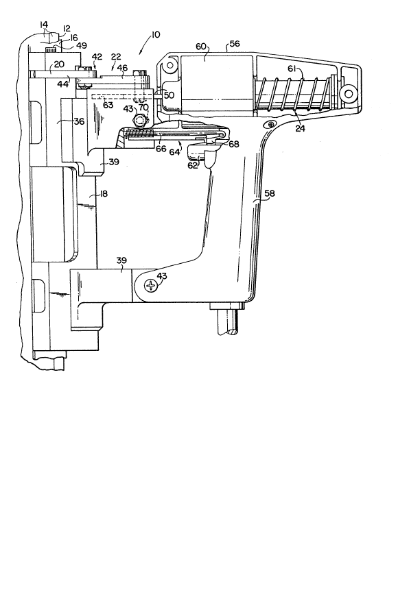
FIG. 1 illustrates a power actuated devlce
embodying the present invention. The device 10 essen~ially
comprises an elongated shoe, indicated generally at 18,
for holding a protective strip, for example the strip 16,
in place along an associated corner such as the corner 12,
a pair of crimping elements 20, 20 pivo~ally and
relça ably supported on the shoe 18 (best sho~n in Flgs. 5
and 6), a toggle mechanism indicated ~enerally at 22 for
moving the crimping elements into crimping engagement with
the protective strip, and an electrically powered
actuator, indicated generally at 24, mounted on the shoe
18 for operating the toggle mechanism 22.
As noted previously, the protectlve strips used
to protect the outside corner6 formed by intersecting
sheetrock or gypsum board wall panels are provided in a
number of different shapes, each one of which generally
complements the contour of an associated corner. FIG. 3
illustrates a protective corner strip adapted to
complement the contour of a right angle-outside wall
corner. The strip 16 is customarily made from sheet metal
and comprises an angle member having two normally disposed
and intersecting sldes 30,30. The sides 30, 30 are
adapted to overlie the edges of the wall panels when the
strip is positioned on the corner 12 formed by the
intersecting panels. After the strip is attached to the
r~i ""
~74~
, :.
l wall with the device 10, ~he corner is finished using a
suitable joint compound which, after hardening, conceal~
the strip. To ensure a firm bond between the metal strlp
and the ~oint compound, ~trip 16 includes a number of
holes 34, 34 which are penetrated by the 13Oint co~pound.
FIG. 4 illustrates a second protective ~trip 15a
having a shape whlch complements an arcuate or rounded
outslde wall corner, such as the corner 12a formed by the
wall panels 14a,14a shown in cross-section in FIG. 7. As
in the ca~e of protectlve corner strip 16, the strip 16a
is customarily made from sheet metal. The strip 16a
comprises an elongated central channel 17 having an
arcuate shape in cross-section and two angularly disposed
tabs 30a,30a extending along the lateral edges of the
channel 17. The tabs are adapted to overlie the edges of
the intersecting wall panels which form the corner.
Again, once the strip 16a is attached to the corner it is
covered with a suitable joint compound.
Referring now to FIGS. 1 and 2, the elongated shoe
18 is constructed to engage and complement the protective
strip 16 and hold the strip and the attaching devlce 10 in
alignment with the corner 12 during the attaching
procedure. The shoe 18 is preferably made from
light-weight rlgid material such as aluminum or plastic and
comprises an angle member 36 defining angularly disposed
abutment surfaces 38, 38. The shoe is constructed so that
,
~7441
1 abutment surfaces 38, 38 engage and substantially
complement the sides 30, 30 of strip 16 when the strip is
held in place along the corner 12. In itB most preferred
embodiment, the shoe 18 is constructed so ~hat abutment
surfaces 38,38 are disposed at an angle slightly less tha~
90 to insure that sides 30,30 of strip 16 are firmly
pressed against the wall panels during the attaching
procedure. The abutment surfaces 38, 38 permlt the
elongated shoe to maintain the strip 16 and device 10 in
alignment with corner 12 during the attaching procedure.
As noted previously, the devlce 10 is provided
with a number of interchangeable shoes of dlffering shape,
each one of which has a contour complementing the contour
of at least an associated portion of a selected protective
strip. For example, FIG. 7 illustrates in cross section a
shoe 18a adapted to engage and complement the protective
strip 16a. The shoe 18a comprises an angle member 36a
defining an elongated central trough 37 having an arcuate
shape in cross-section and two angularly disposed abutment
surfaces 38a,38a extendlng a~ong the lateral edges of the
trough 37. The shoe 18a is constructed BO that the trough
37 engages and substantially complements the central
channel 17 of the protective strip 16a, and the abutment
surfaces 38a,38a engage and complement the tabs 30a,30a
when the strip 16a is held in place along the corner 12a.
'! ?~:.,, ., , , i
~,.. :', , , ,, 1 ' ; . " : '
X007~
l In the embodlment of the invention illustrated in
FIG. 1, the shoe 18 is releasably mounted to the device by
means of upper and lower mounting brackets 39,39.
Referring now to FIGS. 5 and 6, the mounting brackets are
constructed to engage and complement the normally Bisposed
and intersecting outside faces 41,41 of the shoe 18.
Regardless of the contour presented by the shoe ~or
engaginy and complementing the protective strip, the
outside faces 41,41 are alway3 formed at a right angle so
that the brackets 39,39 are useable for mounting any of the
interchangeable shoes. Thus, for example, in the
embodiment of the invention illustrated ln FIG. 7, despite
the fact that the shoe 18a ls constructed with central
trough 37 and angularly disposed abutment surfaces 38a,38a
for complementing the contour of strip 16a, the outslde
faces 41a,41a of the shoe are formed at a right angle for
engagement with mounting brackets 39,39.
The mountinq brackets 39,39 are attached to the
device by means of nut and bolt assemblies 43,43; however,
those skilled in the art will recognlze that the brackets
may be attached to the device in any suitable manner. The
shoe ~s releasably mounted within the brackets by means o~
screws 45,45 shown best in FIG. 2. To remove the shoe 18
from the brackets and mount, for example, shoe 18a, a
workman first disengages the toggle mechanism 22 from the
shoe 18 by removing bolts 49,49 (see FIGS. 5 and 6) and
4~
l then removes screws 45,45. Shoe 18a ls then secured in
the brackets with screws 45,45, and the toggle mechanism
22 is re-mounted on the shoe 18a wlth bolts 49,49. Thus,
in those situations where a workman must attach protec~ive
~trlps to corners of differing contour, he can quickly and
easily adapt the device 10 to attach a protective strip
shaped to complement each particular corner.
Those skilled in the art wlll recognlze tha$ the
mountlng bracket 39,39 can be lntegrally forMed with the
shoe thus elimlnating the need to releasably mount the
shoe wlthin the brackets. If the device is constructed in
thl~ manner, the shoe 18 removed from the actuator 24 by
flrst disengaglng the toggle mechanlsm 22 fron the shoe as ;
dlscussed above and then removing nut and bolt assemblies
43,43.
Referring now to FIGS. 5 and 6, the device 10
further includes a pair of chisel-shaped crimplng elements
20,20 plvotally supported on shoe 18. The crimplng
elements are moveable between an inactive position shown
in FIG. 5 and a crimping posltlon lllustrated in FIG 6.
In the inactive posltion, the ed~es 40,40 of the crimplng
elements do not project beyond the abutment surfaces
38,38. When the crimping elements are driven lnto
crimping position, the edges 40,40 project beyond the
abutment surfaces 38,38 to deform the metal corner strip
16 received wlthin shoe 18, and thereby attach the strip
Z0~74~.
l to the wall panels 14,14, as will be hereinafter explalned
in more detail.
Still referring particularly to FI~S. 5 and 6,
the illustrated cximping elements 20,20 comprise an
integral part of the toggle mechanism 22, which ~oves the
crimping elements between ~heir inactive and crimping
positions. The toggle mechanism is releasably supported
- on shoe 18 and includes a palr of opposite handed llnkages
42,42. Each linkage 42 has two link members 44 and 46
which are pivotally joined to each other. The toggle
mechanism 22 is connected to a reciprocating shaft 50.
The movement of reciprocating shaft 50, toggle mechanism
22 and crimping elements 20,20 will be discussed in more
detail below.
Referring again to FIG. 1, the toggle mechanism 22
is operated by the powered actuator 24 whlch is mounted on
shoe 18. The actuator 24 includes a housing 56 having a
pistol grip 58 extending from it. The shaft 50 is
supported within housing 56 for reciprocating movement
between a forward position lllustrated in Flg. 6 and a
rearward position illustrated ln Flg. 5. Shaft 50 is
reciprocated by a solenold 60 and return spring mechanism
61 mounted within housing 56 and shown schematically ln
Flg. 1. The solenoid and return spring mechanism are
activated by a trigger switch 62 associated with the pistol
grip 58.
20~ 4~.
12
l When ~he solenoid 60 is activated by the swltch
62, the shaft 50, toggle mechanism 22 and crlmpin~
elements 20, 20 move from the posi~ion illustrated in Fig.
5 to that illustrated in Fig. 6. As shaft 50 moves
forward toward the shoe 18 the angle formed by the linkage
members 44 and 46 become substantially more acute, causing
crlmping elements 20,20 to pivot from their lnactive
position and plunge into corner strlp 16 recelved within
shoe 18. When solenoid 60 is deactivated, the return
spring 61 associated with the solenoid moves the shaft 50
away from the shoe. The angle formed by linkage members
44 and 46 once again becomes oblique and crlmping elements
20,20 return to their inactive position. To ensure that
shaft 50 is not deflected as crimping elements 20, 20 are
moved from thelr inactive to crimping po~ition, sha~t 50
18 contained within channel 63 formed in upper mounting
bracket 39.
As an added safety feature, pressure switch
mechanism 64 positioned within housing 56 and linked to
trlgger switch 62 prevents the devlce 10 from belng
actuated unless the devlce ls pressed against a wall or
other suitable surface. Pressure swltch mechanism 64 is
of the type commonly referred to by those skilled ln the
art as a "dead man" switch. The mechanism 64 includes a
spring loaded probe 66 which extends beyond the housing 56
to upper mountin~ bracket 39 and a lock member 68 which
)7~
13
1 locks the trigger switch 62 ln open position. To
disengage lock member 68 and release trigger switch 62,
probe 66 must be in pressing engagement with upper bracket
39. This is accomplished by firmly pushing the device 10
again~t the wall corner during the attaching operation~
The power actuator 24 is mounted to the shoe 18
in such a way as to allow for a slight pivotal movement of
the actuator when the device 10 is pressed against the
corner 12. As the device 10 is pressed firmly against the
corner 12 by a workman, the actuator 24 pivots around
lower nut and bolt assembly 43 until upper nut and bolt
assembly 43 moves from the forward end of slot 70 ~the
position shown in FIG. 1) to the rearward end of the slot
to pressingly engage pressure switch mechanism 64 and
permit trigger switch 62 ~o close.
To install, for example, protective metal ~trip
16 along the outside wall corner 12, a workman aligns the
strip along the corner so that sides 30, 30 of strip 16
overlap wall panels 14, 14. Holdlng the devlce 10 in hls
free hand, the workman aligns device 10 with metal ~trip
16 so that abutment surfaces 38,38 of shoe 18 complement
and overlay sides 30,30 of strip 16. With the metal strip
16 and the device 10 positioned on the corner 12 in this
manner, the workman simply operates the trigger switch 62
to activate solenoid 60 and drive crimping elements 20,20
into the metal strip as illustrated in Fig. 6. When
~i :
;.p,
2()0744~
14
l solenoid 60 is deactivated, crimping elements 20,20 return
to their inactive position so that the device 10 may be
removed from engagement with the strip. The indentations
formed in the metal strip by the crimping elements pro~ect
into wall panels 14,14 ~hereby retaining the strip in
assembly with the wall.
It i~ important to note that the power actuated
device allows the workman to use both hands to allqn and
attach the metal s~rip to the corner of the wall.
Moreover, the danger of metal particles chipped from the
at~aching device is eliminated.
A second embodiment of the present invention i8
illustrated schematically in FIG. 8. The device 100
essentially comprises an shoe, indicated generally at 118,
for holding a protective strip, for example strip 16,
along an associated ~orner such as the corner 12, a pair
of crimping elements 120,120 (only one shown) pivo~ally
and releasably supported on the shoe 118, a toggle
mechanism, indicated at 122, for moving the crimping
elements into crimping engagement wlth the protectlve
strip , and an air-powered actuator, indicated generally
at 124, releasably coupled to the shoe 118 for operating
the toggle mechanism 122.
The air-powered actuator 124 comprises a
pneumatic pis~on and cylinder assembly, indicated
generally at 126, which includes cylinder 128, piston 130
~ , , . ~
74~3
l and piston rod 132. The rod is connected at its rearward
end to piston 130 and is threadably connected at its
forward end to ~oggle mechanism 122 by means of sllde 134.
When not in operation, plston 130 is biased by
means of spring 136 in the position shown in Fig. 8. ~ith
the piston in this position, the crimping elements 120
extend just slightly beyond the abutment surfaces 138rl38
(only one shown) of the shoe 118. When tri~ger swltch 140
is closed, compressed air is introduced into cylinder 128
via hose 142 causing piston 130 to move in the direction
indicated by arrow A. As the piston moves in the
direction of arrow A crimping elements 120,120 are moved
to their crimplng position by toggle mechanism 122 to
attach a protective strip received within shoe 118 to a
wall corner. The compressed air may be supplied from a
portable eompressor (not shown) carried on the workman's
tool belt. Such compressors are compact battery powered
units which are well known to those skilled in the art.
As noted above, the crimping elements are
releasably mounted on the shoe 118 and the shoe is ltself
releasably coupled to the actuator 124. Thus, the shoe
118 is interchangeable with other 3hoes of differlng shape
enabling a workman to quickly and easily adapt the device
100 to attach a protective strip to wall corners of
differing contour.
s~0~)74~
16
l A ~hird embodiment of the present invention is
illustrated schematically in FIGS. 9 and 10. The device
210 e~sentially comprises a shoe, indicated generally at
- 218, for holdlng a pro~ective strip, for example the strip
. 16a, in place along an as~ociated corner such as the
corner 12a, a pair of striking elements 220,220 relea~ably
supported on the shoe 218, a toggle mechanism, indicated
generally at 222 for moving the striklng ela~ent~ into
. strlking engagement wlth-a pair of fasteners 223,223 and a
powered actuator 224 releasably mounted on the shoe 213
.
for operating the toggle mechanism.
The lllustrated strlklng elements 220,220
- comprise an lntegral part of the toggle mechanism 222,
- -- which moves the strlking elements between the inactive
- 15 - : position shown ln FIG. 9 and the fastening position shown
ln FIG. 10. The toggle mechanlsm 222-ls supported on
. plate 228 and releasably supported on the shoe 218. The :
` ~ . mechani~m comprlses two opposlte handed linkages 230,230
.. each of which has two llnk members 232,234 whlch are
20~ plvotally ~oined to each other. Two operatlng llnks
236,236 connect the llnkages to the reclprocated shaft 238
of the powered actuator 224
.. -. The fasteners shown in FIGS. 9 and 10 are
. staples: however, the lnvention is not limited in thi~
regard, and those skilled in the art will recognlæe that
- a~ny-suitable fasteners, such as nails or tacks, may be
.
~ r~
~007~
17
l used. The staples are stored in a pair of magazines
226,226 supported on the shoe 218 and are sequentially
feed by line pressure from a storage position to a
fastening position. When in the fastening posltion, the
staples are situated such that they are struck and driven
by the striking ele~ents 220,22~ as the elements are moved
by the toggle mechanism 222 from the inactive position
shown ln FIG. 9 to the fastening positlon shown ln FIG.
10 .
The device shown in FIGS. 9 and 10 is fitted with
a shoe shaped to complement the contour of an arcuate or
rounded protective strip such as the strip 16b shown in
FIG. 11. The protective strip 16b has a shape which
complements an arcuate or rounded outside wall corner,
such as the corner 12a formed by the wall panels 14a,14a
shown in cross section in FIGS. 9 and 10. The strip 16b
comprises an elongated central channel 17 having an
arcuate shape in cross section. The channel 17 ls
customarily formed from sheet metal and is covered with a
heavy weight construction paper which form two angularly
disposed paper tabs 30b,30b extending along the lateral
edges of the channel 17. The paper tabs are adapted to
overlie the edges of the interse~ting wall panels.
As noted above, the striking elements are
releasably mounted on the shoe 218 and the shoe is itself
releasably mounted on the power actuator 224. Thus, the
~ :: ,,-
4~
l shoe 218 is interchangeable with other shoe~ of dlffering
shape enabling a workman to quickly and easily adapt the
device 210 to attach a protective strip to wall corners of
differing contour.
FIG. 12 illustrates another power actuated device
embodying the present lnvention, indicated generally at
10', for attaching a protective corner strip 16' along an
outside wall corner 12' formed by lntersecting wall panels
14',14'lone shown). The device 10' essentially comprises
an elongated shoe, indicated generally at 18', for holding
the protective strip 16' in place along an associated
corner such as the corner 12', a pair of crimping elements
20',20' (one shown) pivotally supported on the shoe 18', a
toggle mechanism indicated generally at 22' for moving the
crimping elements into crimping engagement with the corner
strip, and a powered actuator, indicated generally at 24',
mounted on the shoe 18' for operating the toggle mechani m
22'.
The elongated shoe 18' i5 preferably made from
light-weight rigid material such as aluminum or plastic
and comprises an angle member 36' defining angularly
disposed abutment surfaces 38',38' (one shown). The shoe
is constructed so that abutment surfaces 38',38' engage
and complement the sides 30', 30' (one shown) of strip 16'
when the strip is held in place along a wall corner such
as the corner 12'. The abutment surfaces 38',38' permit
., : ::: :.: - -:, :: : : ::: : ::: .: : :: . ~ . : . : . : . ,: . :
.. : . . ~ .. .. : .. : ~ ..
~07~4~
1 the elongated shoe to maintain the strip 16' and device
10' in alignmen~ with the corner 12' during the attaching
process.
The crimping elements 20',20' comprise an
integral part of the toggle mechanism 22', which moves the
crimping elements between their inactive and cr1mping
positions. The toggle mechanism is supported on shoe 18'
and includes a pair of opposite handed linkages having two
link member 44' and 46' which are pivotally ~oined to each
other. The toggle mechanism 22' is connected to a
reciprocating shaft 50'.
The toggle mechanism 22' is operated by the
powered actuator 24' which is attached to a frame 54' and
mounted on ~hoe 18'. The actuator 24' includes a hou~ing
56' having a pistol grip 58' extending from it. The shaft
50' is supported within housing 56' for reciprocatlng
movement between a crimping position wherein the crimping
elements extend beyond the abutment surfaces 38',38' and
are in crimping engagement with the corner strips and an
inactive position wherein the crimping elements do not
extend beyond the abutment surfaces 38',38'. Shaft 50' is
reciprocated by a solenoid 60' and return spring mechanism
61' mounted within housing 56' and shown schematically in
Fig. 12. The solenoid and return spring mechanism are
activated by a trigger switch 62' associated with the
pistol grip 58'. To ensure that shaft 50' is not
7~4~
1 deflec~ed as crimping elements 20~ ~20~ are moved from
their inactive ~o crimping position, shaft 50' is
contained within slide 64'.
AB an added safety feature, pressure switch
mechanism 64'' positioned within frame 54' and linked to
trigger switch 62' prevents the device 10' from being
actuated unless the device is pressed against a wall or
other suitable surface. The powered actuator 24~ iS
mounted to frame 54' in such a way as to allow for a
slight pivotal movement of the actuator when the device
10' is pressed against the corner 12'. That is, the
actuator 24~ pivots around nut and bolt assembly 65' until
nut and bolt assembly 68' moves from the rearward end of
the slot 70' (the position 2hown in Fig. 12) to forward
end of the slot'~to engage pressure switch 64' and permit
trigger switch 6f2~ to close.
While tlhe present invention has been described in
one particular e~mbodiment, modificatlons may be made
therein by a pe~son skilled in the art without departing
from the scope olf the invention as expressed in the
following claims.
-
. : - . : . . :.. : . ., :.